
Subscribe to Our Youtube Channel
Related Manuals for Woodward LS-5 v2 Series


Summary of Contents for Woodward LS-5 v2 Series
- Page 1 Released LS-5 v2 Series Technical Manual Circuit Breaker Control LS-5x2 (v2) 2breaker Software Version 2.00xx Document ID: 37650, Revision: A (Build 45902)
- Page 2 This is no translation but the original Technical Manual in English. Designed in Germany. Woodward GmbH Handwerkstr. 29 70565 Stuttgart Germany Telephone: +49 (0) 711 789 54‑510 Fax: +49 (0) 711 789 54‑101 Email: stgt-info@woodward.com Internet: http://www.woodward.com © 2020 Woodward GmbH LS-5 v2 Series 37650...
- Page 3 • RS-232 connector: DPC-RS-232 direct configuration cable – P/N 5417-557 The LS-5 Series are circuit breaker control units for engine-generator system management applications. The control units can be used stand-alone or in applications in combination with Woodward easYgen-3400/3500 genset control units. 37650 LS-5 v2 Series...
- Page 4 • The easYgen(s) close and open their own generator breaker. • The LS-5 at the interchange point closes and opens the GGB and MCB, or it serves an ATS switch. For a listing of additional application modes and setups please refer to ╚═▷ “6 Application”. LS-5 v2 Series 37650...
- Page 5 Fig. 3: Scope of delivery - schematic LS-5 circuit breaker control Product CD-ROM (configuration software and manual) LS-52x only: Clamp fastener installation material - 4x LS-52x only: Screw kit installation material - 8x 37650 LS-5 v2 Series...
-
Page 6: Table Of Contents
................. . . LS-5 v2 Series... - Page 7 ............... . . 37650 LS-5 v2 Series...
- Page 8 ..............LS-5 v2 Series...
- Page 9 ............... . 37650 LS-5 v2 Series...
- Page 10 ............. . . LS-5 v2 Series...
- Page 11 ..............37650 LS-5 v2 Series...
- Page 12 ..............LS-5 v2 Series...
- Page 13 ............... . 37650 LS-5 v2 Series...
-
Page 14: General Information
(not direct mains connected). Softwareversion 2.0007. Introduction of a Closed Transition Monitoring. Default settings TPDO1. With the default setting the data telegram 5301 is not send anymore. Introduction of a Synchronization type (one phase or three phase). LS-5 v2 Series 37650... -
Page 15: Depiction Of Notes And Instructions
Marking Explanation ⚙ Start of a procedure list ▷ Step-by-step instructions ▶ Results of action steps ╚═▷ References to sections of these instructions and to other relevant documents • Listing without fixed sequence 37650 LS-5 v2 Series... -
Page 16: Copyright And Disclaimer
All information and instructions in this manual have been provided under due consideration of applicable guidelines and regulations, the current and known state of the art, as well as our many years of in-house experience. Woodward assumes no liability for damages due to: •... -
Page 17: Service And Warranty
In addition, our employees are constantly interested in new information and experiences that arise from usage and could be valuable for the improvement of our products. Warranty terms Please enquire about the terms of warranty from your nearest Woodward representative. For our contact search webpage please go to: ══▷ http://www.woodward.com/ Directory.aspx Safety 1.4.1... -
Page 18: Personnel
The workforce must only consist of persons who can be expected to carry out their work reliably. Persons with impaired reactions due to, for example, the consumption of drugs, alcohol, or medication are prohibited. When selecting personnel, the age-related and occupation-related regulations governing the usage location must be observed. LS-5 v2 Series 37650... -
Page 19: General Safety Notes
37650 LS-5 v2 Series... - Page 20 • Make sure the charging device is turned off before disconnecting the battery from the system. Unit includes a lithium backup battery for Real Time Clock. Field replacement of the battery is not allowed. In case of battery replacement please contact your Woodward service partner. Electrostatic discharge ⚙ ᐳ...
- Page 21 For additional information on how to prevent damage to electronic components caused by improper handling, read and observe the precautions in: • "Woodward manual 82715, Guide for Handling and Protection of Electronic Controls, Printed Circuit Boards, and Modules". Notes on marine usage...
-
Page 22: Protective Equipment And Tools
The cumulative required tools are detailed below: Special tool: Torque screwdriver A torque-screwdriver allow fastening of screws to a precisely specified torque. • Note the required torque range individually specified in the tasks listed in this manual. LS-5 v2 Series 37650... -
Page 23: System Overview
• and (plastic housing variant only) an adhesive label (part of delivery) should be removed to make the second breaker at the front panel visible. Please refer to this manual (LS-5x2 v2 series device) for details. 37650 LS-5 v2 Series... -
Page 24: Display And Status Indicators
• ╚═▷ “5 Operation” provides information on how to access the unit via the front panel or remotely using the ToolKit software provided by Woodward. • ╚═▷ “6 Application” provides application examples as well as instructions for the corresponding required configuration. - Page 25 5) on the front plate. The LEDs indicate the following states: State Indication NOT illuminated Not triggered (LogicsManager condition not met). Illuminated red Triggered (LogicsManager condition met). Tab. 1: LEDs 'LogicsManager states' State Indication NOT illuminated CPU error/unit offline. 37650 LS-5 v2 Series...
- Page 26 12962 to 12969. The conditions printed next to the LEDs on the sheet metal housing represent the corresponding LogicsManager's parameter defaults. This is done by an inserted paper strip that can be exchanged by customer. LS-5 v2 Series 37650...
- Page 27 The LS-51x comes with a paper strip describing the default LED conditions. There is a slot behind terminal 43..59. The product CD-ROM offers a template to create own text. Please take care that the description is correct and will not mislead user. Woodward cannot assume any liability caused by your "wrong" text.
-
Page 28: Hardware Interfaces (Terminals)
For information on how to setup connections refer to ╚═▷ “3.3 Setup Connections”. For information on the interfaces and protocols refer to ╚═▷ “7 Interfaces And Protocols”. Application Modes The circuit breaker control provides the following basic functions via the application modes listed below. LS-5 v2 Series 37650... -
Page 29: Operation Modes
• 02.30 Dead Bus Closure Condition • 02.28 Sync. Check Relay WARNING! No dead bus interlocking! Synch. Check is intended to be a redundant check function enhancing system security. Don't use for CBA or CBB control! 37650 LS-5 v2 Series... - Page 30 The command variable Sync. Check Relay 02.28 ╚═▷ “9.3.4.3 Group 02: Systems Condition” is true, if the phase matching synchronisation conditions are met according to parameters 5701, 5702, 5700, 8825, 8824, 5703, 5704, and 5707 (parameter 5729 doesn’t care) or LS-5 v2 Series 37650...
- Page 31 2.5 Synch. Check Functionality if the dead bus closure conditions are met according to parameters 3432, 5820, 8805, 8802, 8803, and 8804. For more details refer to ╚═▷ “4.4.2.3.1 Synchronization CBA” ╚═▷ “4.4.2.1 Dead Bus Closure CB”. 37650 LS-5 v2 Series...
-
Page 32: Installation
• Special tool: Torque screwdriver Proceed as follows to install the unit using the screw kit: 1. ▷ Fig. 9: Sheet metal housing - drill plan Drill the holes according to the dimensions in ╚═▷ Fig. 9 (dimensions shown in mm). LS-5 v2 Series 37650... -
Page 33: Mount Unit (Plastic Housing)
• Some versions of the plastic housing are not equipped with nut inserts and may not be fastened with the screw kit. • In order to enhance the protection to IP 66, fasten the unit with the screw kit instead of the clamp fastener hardware. 37650 LS-5 v2 Series... - Page 34 + 1.0 mm Housing dimension 136 mm Width Total 219 mm — Panel cutout 186 mm + 1.1 mm Housing dimension 184 mm Depth Total 61 mm — The maximum permissible corner radius is 3.5 mm. LS-5 v2 Series 37650...
-
Page 35: Clamp Fastener Installation
Do not completely insert the screws into the clamp inserts. Insert the unit into the panel cutout. Verify that the unit fits correctly in the cutout. If the 4. ▷ panel cutout is not big enough, enlarge it accordingly. 37650 LS-5 v2 Series... - Page 36 Do not exceed the recommended tightening torque of 0.1 Nm. 7. ▷ Fig. 16: Reattach terminals Reattach the wire connection terminal strip (╚═▷ Fig. 16) and secure them with the side screws. LS-5 v2 Series 37650...
-
Page 37: Screw Kit Installation
Insert the unit into the panel cutout. Verify that the unit fits correctly in the cutout. If the panel cutout is not big enough, enlarge it accordingly. Insert the screws and tighten to 0.6 Nm (5.3 pound inches) of torque. 3. ▷ 37650 LS-5 v2 Series... -
Page 38: Setup Connections
Tab. 3: Conversion chart - wire sizes 3.3.1 Terminal Allocation General notes The device terminals are allocated as follows: • Plastic housing - shown in ╚═▷ Fig. 18 • Sheet metal housing - shown in ╚═▷ Fig. 19 LS-5 v2 Series 37650... -
Page 39: Wiring Diagram
╚═▷ “Electrical hazards”. Fig. 18: Plastic housing (rear view) Fig. 19: Sheet metal housing 3.3.2 Wiring Diagram LS-5x2 v2 Series The following figure shows the hardware situation. The 2nd drawing offers a functional short description additionally. 37650 LS-5 v2 Series... - Page 40 LS-5x1 series devices to the LS-5x1 v2 and LS-5x2 v2 series devices. 01 02 03 04 05 06 07 08 10 11 12 13 14 15 16 17 18 19 20 21 22 23 24 25 26 27 28 29 Fig. 20: Label/print LS-5x2 v2 series wiring LS-5 v2 Series 37650...
- Page 41 Fixed: Reply „CB A is open“ (isolated) 12/24 V Power supply 8 to 40 V (Display version Function Earth System A current only) isolated) CAN-L CAN bus (isolated) CAN-H RS-485-b RS-485 interface (isolated) RS-485-a Fig. 21: Wiring diagram (LS-5x2 v2 series) 37650 LS-5 v2 Series...
-
Page 42: Power Supply
• The conductor providing the connection must have a wire larger than or equal to 2.5 mm² (14 AWG). The connection must be performed properly. Woodward recommends to use one of the following slow-acting protective devices in the supply line to terminal 53: •... -
Page 43: Voltage Measuring
The control unit will not measure voltage correctly if the 120 V and 480 V inputs are utilized simultaneously. • Never use both sets of voltage measuring inputs. Woodward recommends protecting the voltage measuring inputs with slow-acting fuses rated for 2 to 6 A. 3.3.4.1 Breaker interaction The drawing below shows a typical example how the LS-5x2 v2 is connected. -
Page 44: System A Voltage
130 V, the 120 V input terminals must be used for proper measurement. If parameter 1800 ("SyA PT secondary rated volt.") is configured with a value between 131 and 480 V, the 480 V input terminals must be used for proper measurement. LS-5 v2 Series 37650... - Page 45 A system that is connected to the load through a 3-phase, 4-wire connection but have the device wired for a 3-phase, 3-wire installation may have the L2 phase grounded on the secondary side. In this application the device will be configured for 3-phase, 4-wire OD for correct power measurement. 37650 LS-5 v2 Series...
- Page 46 Terminal assignment 3Ph 4W Wiring terminals Rated voltage (range) 120 V (50 to 130 V 480 V (131 to 480 V eff. eff. Measuring range 0 to 150 Vac 0 to 600 Vac (max.) Terminal Phase LS-5 v2 Series 37650...
- Page 47 Terminal assignment 3Ph 4W Wiring terminals Rated voltage (range) 120 V (50 to 130 V 480 V (131 to 480 V eff. eff. Measuring range 0 to 150 Vac 0 to 600 Vac (max.) Terminal Phase 37650 LS-5 v2 Series...
- Page 48 Terminal assignment 3Ph 3W Wiring terminals Rated voltage (range) 120 V (50 to 130 V 480 V (131 to 480 V eff. eff. Measuring range 0 to 150 Vac 0 to 600 Vac (max.) Terminal Phase LS-5 v2 Series 37650...
- Page 49 Terminal assignment 1Ph 3W Wiring terminals Rated voltage (range) 120 V (50 to 130 V 480 V (131 to 480 V eff. eff. Measuring range 0 to 150 Vac 0 to 600 Vac (max.) Terminal Phase 37650 LS-5 v2 Series...
- Page 50 Fig. 35: Measuring inputs - 1Ph 2W (phase neutral) Terminal assignment 1Ph 2W Wiring terminals Rated voltage (range) 120 V (50 to 130 V 480 V (131 to 480 V eff. eff. Measuring range 0 to 150 Vac 0 to 600 Vac (max.) Terminal LS-5 v2 Series 37650...
- Page 51 Fig. 37: Measuring inputs - 1Ph 2W (phase-phase) Terminal assignment 1Ph 2W Wiring terminals Rated voltage (range) 120 V (50 to 130 V 480 V (131 to 480 V eff. eff. Measuring range 0 to 150 Vac 0 to 600 Vac (max.) Terminal 37650 LS-5 v2 Series...
-
Page 52: System B Voltage
Fig. 38: Voltage measuring - system B - wiring Terminal Description System B voltage - L1 120 Vac 2.5 mm² 480 Vac 2.5 mm² System B voltage - L2 120 Vac 2.5 mm² 480 Vac 2.5 mm² LS-5 v2 Series 37650... - Page 53 Terminal assignment 3Ph 4W Wiring terminals Rated voltage (range) 120 V (50 to 130 V 480 V (131 to 480 V eff. eff. Measuring range 0 to 150 Vac 0 to 600 Vac (max.) Terminal Phase 37650 LS-5 v2 Series...
- Page 54 Terminal assignment 3Ph 3W Wiring terminals Rated voltage (range) 120 V (50 to 130 V 480 V (131 to 480 V eff. eff. Measuring range 0 to 150 Vac 0 to 600 Vac (max.) Terminal Phase LS-5 v2 Series 37650...
- Page 55 Terminal assignment 1Ph 3W Wiring terminals Rated voltage (range) 120 V (50 to 130 V 480 V (131 to 480 V eff. eff. Measuring range 0 to 150 Vac 0 to 600 Vac (max.) Terminal Phase 37650 LS-5 v2 Series...
- Page 56 Fig. 46: Measuring inputs - 1Ph 2W (phase neutral) Terminal assignment 1Ph 2W Wiring terminals Rated voltage (range) 120 V (50 to 130 V 480 V (131 to 480 V eff. eff. Measuring range 0 to 150 Vac 0 to 600 Vac (max.) Terminal LS-5 v2 Series 37650...
- Page 57 Fig. 48: Measuring inputs - 1Ph 2W (phase-phase) Terminal assignment 1Ph 2W Wiring terminals Rated voltage (range) 120 V (50 to 130 V 480 V (131 to 480 V eff. eff. Measuring range 0 to 150 Vac 0 to 600 Vac (max.) Terminal 37650 LS-5 v2 Series...
-
Page 58: Current Measuring
General notes WARNING! Dangerous voltages due to missing load • Before disconnecting the device, ensure that the current transformer (CT) is short- circuited. Generally, one line of the current transformers secondary must be grounded close to the LS-5 v2 Series 37650... - Page 59 Tab. 7: Current measuring - system A - terminal assignment 3.3.5.1.1 Parameter Setting 'L1 L2 L3' Schematic and terminals SyA L1 SyA L2 SyA L3 Fig. 50: Current measuring - system A, L1 L2 L3 Wiring terminals Terminal 37650 LS-5 v2 Series...
-
Page 60: Current Measuring (System B)
— — s1 (k) L3 s2 (l) L3 3.3.5.2 Current Measuring (System B) General notes WARNING! Dangerous voltages due to missing load • Before disconnecting the device, ensure that the current transformer (CT) is short- circuited. LS-5 v2 Series 37650... - Page 61 Parameter Setting 'Phase L1' 'Phase L2' 'Phase L3' Schematic and terminals SyB L1 SyB L2 SyB L3 Phase L1 Phase L3 Phase L2 Fig. 53: Current measuring - system B, 'Phase L1' 'Phase L2' 'Phase L3' Wiring terminals 37650 LS-5 v2 Series...
-
Page 62: Power Measuring
If the unit's current transformers are wired according to the diagram (╚═▷ Fig. 54), the following values are displayed. Terminal Description System A current System B current Description Sign displayed Positive real power Power flow from System B to + Positive System A LS-5 v2 Series 37650... -
Page 63: Power Factor Definition
Electrical load whose current waveform lags the Electrical load whose current waveform leads voltage waveform thus having a lagging power the voltage waveform thus having a leading factor. Some inductive loads such as electric power factor. Some capacitive loads such as 37650 LS-5 v2 Series... -
Page 64: Analog Input 0/4 To 20 Ma
1.0 A −90° −90° Fig. 57: Phasor diagram: capacitive load (left) and inductive load (right) 3.3.8 Analog Input 0/4 to 20 mA This Analog Input AI01 is fixed to external power measurement System A or System B. LS-5 v2 Series 37650... - Page 65 LS-5 chassis ground and terminal 55 does not exceed +/- 2.5 V. Fig. 59: Analog input - wiring single-pole sender (20 mA) Terminal Description Analog input [AI 01] ground, connected with engine ground 2.5 mm² Analog input [AI 01] 2.5 mm² 37650 LS-5 v2 Series...
-
Page 66: Discrete Inputs
Preconfigured to "Enable to close 2.5 mm² CBA" Discrete Input [DI 08] Fixed to "Reply: CBA is open" 2.5 mm² • configurable via LogicsManager Operation logic Discrete inputs may be configured to normally open (N.O.) or normally closed (N.C.) states. LS-5 v2 Series 37650... -
Page 67: Relay Outputs
For information on interference suppressing circuits when connecting 24 V relays, please refer to ╚═▷ “3.5 Connecting 24 V Relays”. Schematic and terminals Fig. 64: Relay outputs - schematic Terminal Description Common N.O. Form A Relay output [R 01] Fixed to "Ready for operation" mm² 37650 LS-5 v2 Series... -
Page 68: Serial Interface
• N.O.: normally open (make) contact N.C.: normally closed (break) contact 3.3.11 Serial Interface 3.3.11.1 RS-485 Interface General notes Please note that the RS-485 interface only operates in half-duplex mode. Pin assignment Terminal Description RS-485-B (TxD-) LS-5 v2 Series 37650... -
Page 69: Service Port
Service Port Service port connector Fig. 66: Service port connector (RJ-45) The Woodward specific service port is a connector (RJ-45) to extend the interfaces of the controller. The service port can be only used in combination with an optional Woodward direct configuration cable (DPC). - Page 70 • DPC-USB direct configuration cable • DPC-RS-232 direct configuration cable DPC-USB direct configuration cable Use the DPC-USB direct configuration cable if you want to connect the Woodward controller to an external device (master) which is equipped with an USB port. Order item number: •...
-
Page 71: Can Bus Interface
'Split termination concept' as shown. • Divide the termination resistance into 2x60 Ohms with a center tap connected to ground via a capacitor of 10 to 100 nF (╚═▷ Fig. 69). 37650 LS-5 v2 Series... - Page 72 • Not all devices on the bus are using identical baud rates • Termination resistor(s) are missing • The configured baud rate is too high for wiring length • The CAN bus cable is routed in close proximity with power cables LS-5 v2 Series 37650...
-
Page 73: Connecting 24 V Relays
Released 3 Installation 3.5 Connecting 24 V Relays Woodward recommends the use of shielded, twisted-pair cables for the CAN bus (see examples). • Lappkabel Unitronic LIYCY (TP) 2×2×0.25 • UNITRONIC-Bus LD 2×2×0.22 Connecting 24 V Relays NOTICE! Damage to adjacent electronic components due to induced voltages •... - Page 74 High energy absorption Very simple setup Suitable for AC voltage Reverse polarity protected HF attenuation by energy Exact dimensioning required storage Immediate shut-off limiting Attenuation below limiting voltage Very suitable for AC voltage Reverse polarity protected LS-5 v2 Series 37650...
-
Page 75: Configuration
• 23 = 23rd hour of the day (11 pm). 1709 Minute 0 to 59 min The minute of the clock time is set here. [real-time clock] Example • 0 = 0th minute of the hour • 59 = 59th minute of the hour 37650 LS-5 v2 Series... - Page 76 (DST) provisions. If daylight saving time is enabled, the real-time clock will automatically be advanced by one hour when the configured DST begin date and time is reached and falls back again by one hour when the LS-5 v2 Series 37650...
- Page 77 DST starts on the 3rd configured weekday of the DST begin month. DST starts on the 4th configured weekday of the DST begin month. [Last] DST starts on the last configured weekday of the DST begin month. 37650 LS-5 v2 Series...
- Page 78 (parameter 4591) is set to "On". 4595 DST end nth. weekday The order number of the weekday for the DST begin date is configured here. DST ends on the 1st configured weekday of the DST begin month. LS-5 v2 Series 37650...
- Page 79 If daylight saving time starts at 2:00 am on the 2nd Sunday in March and ends at 2:00 am on the 1st Sunday in November, the unit has to be configured like shown in ╚═▷ Tab. 11 to enable an automatic change to daylight saving time and back to standard time. 37650 LS-5 v2 Series...
-
Page 80: Configure Display
The controller utilizes a password protected multi-level configuration access hierarchy. This permits varying degrees of access to the parameters being granted by assigning unique passwords to designated personnel. A distinction is made between the access levels as follows: LS-5 v2 Series 37650... - Page 81 The current code level is indicated by the corresponding numeric value (e.g. »Code level display«: »1«) in the configuration menu screens. The value indicates that all parameters of a higher code level are "locked". Parameter Setting range Description [Default] 37650 LS-5 v2 Series...
-
Page 82: System Management
CAN bus. The address assigned to the controller may only be used once. All other bus addresses are calculated on the number entered in this parameter. Notes LS-5 v2 Series 37650... - Page 83 {x} Alarm class) or "Self acknowledge" (DI {x} Self acknowledge). In case of misconfiguration an external access is only possible via external interface or ToolKit configuration software. In case of misconfiguration the access is only possible via an external 37650 LS-5 v2 Series...
- Page 84 This parameter is only displayed, if Factory Settings (parameter 10417) is set to "Yes". This function is used for uploading application software and may only be used by authorized Woodward service personnel! 1706 Clear eventlog The event history will be cleared.
-
Page 85: Password System
Supercommissioning level code 1 to 9999 The password for the code level "Supercommissioning" is defined in this parameter. Refer to ╚═▷ “4.1.3 Enter Password” for default values. 4.1.6 Configure Status/Monitoring (home) screen Configure HMI Configurable via ToolKit only! 37650 LS-5 v2 Series... -
Page 86: Configure Measurement
B side Notes The max. possible number of characters is eight but only five will be displayed correctly on HMI/display. Tab. 13: Parameters Customer Screen Configuration Configure Measurement Parameter Setting range Description [Default] LS-5 v2 Series 37650... - Page 87 This value specifies the system B rated current, which is used as a [300 A] reference figure for related functions. 1858 1Ph2W voltage measuring [Phase - phase] The unit is configured for measuring phase-phase voltages if 1Ph 2W measuring is selected. 37650 LS-5 v2 Series...
- Page 88 Monitoring refers to the following voltages: • VL12, VL23 and VL31 (parameter 1771 configured to "Phase-phase") • VL1N, VL2N and VL3N (parameter 1771 configured to "Phase-neutral") • VL12, VL23, VL31, VL1N, VL2N and VL3N (parameter 1771 configured to "All") LS-5 v2 Series 37650...
- Page 89 All three phases are monitored. Measurement, display and protection are adjusted according to the rules for 3-phase measurement. Monitoring refers to the following currents: IL1, IL2, IL3 Phase L{1/2/3} Only one phase is monitored. Measurement, display and protection 37650 LS-5 v2 Series...
- Page 90 "Phase - neutral" and Line-Line (Delta connected system) if parameter 1858 is configured to "Phase - phase". Measurement, display and protection are adjusted according to the rules for phase-phase systems. Monitoring refers to the following voltages: • VL1N, VL12 LS-5 v2 Series 37650...
-
Page 91: Configure Transformer
This controller is available in two different hardware versions with either 1A [../1] or 5A [../5] current transformer inputs. The setpoints for specific current parameters will differ depending upon the hardware version, indicated on the data plate. • [1] LS-5xx-1 = Current transformer with ../1 A rated current 37650 LS-5 v2 Series... - Page 92 The control unit is equipped with dual voltage measuring inputs. The voltage range of these measurement inputs is dependent upon input terminals are used. This value refers to the secondary voltages of the potential LS-5 v2 Series 37650...
- Page 93 • Rated voltage: 120 Vac (this parameter configured between 50 and 130 V) System B voltage: Terminals 22/24/26/28 • Rated voltage: 480 Vac (this parameter configured between 131 and 480 V) 37650 LS-5 v2 Series...
-
Page 94: Configure Monitoring
[Phase - phase] The phase-phase voltage will be monitored and all subsequent parameters concerning voltage monitoring "system A" are referred to this value (VL-L). LS-5 v2 Series 37650... -
Page 95: System A Operating Voltage / Frequency
The system A values must be within these ranges to synchronize the CBA. • It is recommended to configure the operating limits within the monitoring limits. 37650 LS-5 v2 Series... - Page 96 100.0 to 150.0 % The maximum permissible positive deviation of the system A frequency [105.0 %] from the rated system frequency (parameter 1750) is configured here. This value may be used as a frequency limit switch. The conditional LS-5 v2 Series 37650...
-
Page 97: System A Decoupling
(╚═▷ “4.3.1.6 System A Underfrequency (Level 1 & 2) ANSI# 81U”) • Underfrequency level 2 ╚═▷ “4.3.1.6 System A Underfrequency (Level 1 & 2) ANSI# 81U”() • Overvoltage level 1 if parametrized for decoupling (╚═▷ “4.3.1.7 System A Overvoltage (Level 1 & 2) ANSI# 59”) 37650 LS-5 v2 Series... - Page 98 If the reply "CBA open" is not present within the delay configured, the CBB will be opened as well. System A decoupling is carried out according to the following parameters. If one of the subordinate monitoring LS-5 v2 Series 37650...
- Page 99 3112 Self acknowledge The control unit automatically clears the alarm if the fault condition is no longer detected. [No] The control unit does not automatically reset the alarm when the fault condition is no longer detected. 37650 LS-5 v2 Series...
-
Page 100: Phase Shift
The result is, that the power circuit breaker that disconnects from the mains, is opened, the message "SyA. phase shift" is displayed, and the logical command variable "07.14" is enabled. The "Phase shift" configuration parameters are located below the "SyA. decoupling" function menu on the display. LS-5 v2 Series 37650... - Page 101 3052 Self acknowledge [Yes] The control unit automatically clears the alarm if the fault condition is no longer detected. The control unit does not automatically reset the alarm when the fault condition is no longer detected. 37650 LS-5 v2 Series...
-
Page 102: Df/Dt (Rocof)
0.10 to 2.00 s If the monitored rate of df/dt exceeds the threshold value for the delay time [0.10 s] configured here, an alarm will be issued. If the monitored df/dt exceeds the threshold (plus the hysteresis) again LS-5 v2 Series 37650... -
Page 103: System A Overfrequency (Levels 1 & 2) Ansi# 81O
"SyA. overfrequency 2" and the logical command variable "07.06" or "07.07" will be enabled. Refer to ╚═▷ “9.1.1 Triggering Characteristics” for the triggering characteristic of this monitoring function. The system A overfrequency Level 2 limit configuration parameters are located below the "SyA. decoupling" function menu on the display. 37650 LS-5 v2 Series... - Page 104 2858 (Limit 1/Limit 2) longer detected. [No] The control unit does not automatically reset the alarm when the fault condition is no longer detected. The alarm must be acknowledged and reset by manually pressing the LS-5 v2 Series 37650...
-
Page 105: System A Underfrequency (Level 1 & 2) Ansi# 81U
(Limit 1/Limit 2) 2904: [99.6 %] defined here. 2910: [98.0 %] If this value is reached or exceeded for at least the delay time without interruption, the action specified by the alarm class is initiated. Notes 37650 LS-5 v2 Series... -
Page 106: System A Overvoltage (Level 1 & 2) Ansi# 59
1851). There are two overvoltage alarm levels available in the control. Both alarms are definite time alarms and are illustrated in the figure below. The figure diagrams a frequency trend and the associated pickup times and length of the alarms. Monitoring of the voltage is done in two steps. LS-5 v2 Series 37650... - Page 107 2951 Alarm class Class A/B/C/D/E/F/Control Each limit may be assigned an independent alarm class that specifies 2957 (Limit 1/Limit2) 2951: [A] what action should be taken when the limit is surpassed. 2957: [B] 37650 LS-5 v2 Series...
-
Page 108: System A Undervoltage (Level 1 & 2) Ansi# 27
"SyA. undervoltage 2" and the logical command variable "07.12" or "07.13" will be enabled. Refer to ╚═▷ “9.1.1 Triggering Characteristics” for the triggering characteristic of this monitoring function. The system A undervoltage Level 2 limit configuration parameters are located below the "SyA. decoupling" function menu on the display. LS-5 v2 Series 37650... - Page 109 3008 Limit 1/Limit 2 longer detected. [No] The control unit does not automatically reset the alarm when the fault condition is no longer detected. The alarm must be acknowledged and reset by manually pressing the 37650 LS-5 v2 Series...
-
Page 110: System A Voltage Asymmetry
This monitoring function is only enabled if system A voltage measuring (parameter 1851) is configured to "3Ph 4W" or "3Ph 3W". Parameter Setting range Description [Default] 3921 Monitoring [On] Voltage asymmetry monitoring is carried out according to the following parameters. No monitoring is carried out. LS-5 v2 Series 37650... - Page 111 3926 Monitoring lockable Monitoring for fault conditions is only performed if "Lock Monitoring Status 24.40" is false. [No] Monitoring for this fault condition is continuously enabled regardless of "Lock Monitoring Status 24.40". 37650 LS-5 v2 Series...
-
Page 112: 4.3.1.10 System A Voltage Increase
Monitoring Voltage increase monitoring is carried out according to the following parameters. [Off] No monitoring is carried out. 8807 Limit 100 to 150 % The percentage voltage value that is to be monitored is defined here. LS-5 v2 Series 37650... -
Page 113: 4.3.1.11 Setup System A For Vde-Ar-N 4105
4.3.1.11 Setup System A for VDE-AR-N 4105 General notes The German Grid Code VDE-AR-N 4105 instructs the handling of electrical energy sources running parallel to the low voltage grid. This rule has an impact with some items on the 37650 LS-5 v2 Series... - Page 114 Woodward solves this requirement with the use of a minimum of two devices acting as a system (for example two LS-5 or an easYgen with VDE-AR-N 4105 functionality and an LS-5).
- Page 115 3054 Phase shift: Limit 1-phase (checked, if enabled) 3055 Phase shift: Limit 3-phase (checked, if enabled) 3104 df/dt: Limit (checked, if enabled) 3105 df/dt: Delay (checked, if enabled) Disable mains monitoring 15159 Disable mains monitoring 37650 LS-5 v2 Series...
- Page 116 CAN 1 If the diagnostic function is enabled, the related messages can be received via CAN 1. Notes The following alarms can be triggered: • Missing member 4105 • Para. alignment 4105 LS-5 v2 Series 37650...
- Page 117 The alarm must be acknowledged and reset by manually pressing the appropriate buttons or by activating the LogicsManager output "External acknowledgment" (via a discrete input or via an interface). 37650 LS-5 v2 Series...
- Page 118 The alarm must be acknowledged and reset by manually pressing the appropriate buttons or by activating the LogicsManager output "External acknowledgment" (via a discrete input or via an interface). LS-5 v2 Series 37650...
-
Page 119: 4.3.1.12 Qv Monitoring
“Delay step 1” (parameter 3283) or "Delay step 2" (parameter 3284). The LogicsManager command flags 07.29 and 07.30 can be additionally used to cause other actions according to the corresponding regulations of the grid. 37650 LS-5 v2 Series... - Page 120 3291 Reactive power threshold 2 to 100 % The percentage reactive value that is to be monitored is defined here. [5 %] If the absolute value of reactive power Q is higher than this threshold, the LS-5 v2 Series 37650...
- Page 121 LogicsManager output "External acknowledgement" (via a discrete input or via an interface). 3294 Monitoring lockable Monitoring for fault conditions is only performed if Lock Monitoring Status 24.40 is false. 37650 LS-5 v2 Series...
-
Page 122: 4.3.1.13 System A Time-Dependent Voltage
The curve shows the device default values according to a typical grid code requirement. The time points should always have an ascending order. The fallback threshold (parameter 4978) should always be configured to a value higher/lower than the initial threshold (parameter 4970). LS-5 v2 Series 37650... - Page 123 Time-dependent voltage monitoring is carried out according to the following parameters. [Off] No monitoring is carried out. 4952 AND characteristics Each phase falls below/exceeds the threshold for tripping. [Off] At least one phase falls below/exceeds the threshold for tripping. 37650 LS-5 v2 Series...
- Page 124 0.00 to 320.00 s The time values of time-dependent voltage monitoring time points are 4962 [x = 1 to 7] 4961: [0.00 s] configured here. 4963 4962: [0.15 s] 4964 4963: [0.15 s] 4965 4964: [0.70 s] LS-5 v2 Series 37650...
- Page 125 Monitoring for fault conditions is only performed if "Lock Monitoring Status 24.40" is false. [No] Monitoring for this fault condition is continuously enabled regardless of "Lock Monitoring Status 24.40". 4989 SyA. decou-pling Time-dependent voltage monitoring does cause decoupling. 37650 LS-5 v2 Series...
-
Page 126: System A Phase Rotation
"3Ph 4W" or "3Ph 3W" and the measured voltage exceeds 50 % of the rated voltage (parameter 1768) or if system A voltage measuring (parameter 1853) is configured to "1Ph 2W" (in this case, the phase rotation is not evaluated, but defined by the 1Ph2W phase rotation (parameter 1859)). LS-5 v2 Series 37650... -
Page 127: System B
Monitoring for fault conditions is only performed if "Lock Monitoring Status 24.40" is false. [No] Monitoring for this fault condition is continuously enabled regardless of "Lock Monitoring Status 24.40". 4.3.2 System B Parameter Setting range Description [Default] 37650 LS-5 v2 Series... -
Page 128: System B Operating Voltage / Frequency
B rated voltage (parameter 1768) is configured here. This value may be used as a voltage limit switch. The conditional state of this switch may be used as a command variable for the LogicsManager (02.03). LS-5 v2 Series 37650... -
Page 129: System B Voltage Phase Rotation
The directions of rotation are differentiated as "clockwise" and "counter clockwise". With a clockwise field the direction of rotation is "L1-L2-L3"; with a counter clockwise field the direction of rotation is "L1-L3-L2". 37650 LS-5 v2 Series... - Page 130 The alarm must be acknowledged and reset by manually pressing the appropriate buttons or by activating the LogicsManager output "External acknowledgement" (via a discrete input or via an interface). LS-5 v2 Series 37650...
-
Page 131: Breaker
Monitoring is disabled. 2621 CBA alarm class Class A/B Each limit may be assigned an independent alarm class that specifies what action should be taken when the limit is surpassed. Notes 37650 LS-5 v2 Series... -
Page 132: Synchronization Cba
If it was not possible to synchronize the CBA within the time configured [60 s] here, an alarm will be issued. The message "CBA syn. timeout" is issued and the logical command variable "08.31" will be enabled. LS-5 v2 Series 37650... -
Page 133: Cba Unload Mismatch
"CBA unload mismatch" and the logical command variable "08.36" will be enabled. 8836 Alarm class Class A/B/C/D/E/F/Control Each limit may be assigned an independent alarm class that specifies 37650 LS-5 v2 Series... -
Page 134: Cbb
CBB alarm will be initiated (refer to parameter "CBB open monitoring", parameter 3420). If this protective function is triggered, the display indicates "CBB fail to open" and the logical command variable "08.06" will be enabled. LS-5 v2 Series 37650... -
Page 135: Synchronization Cbb
Monitoring for this fault condition is continuously enabled regardless of "Lock Monitoring Status 24.40". 4.3.3.5 Synchronization CBB For synchronization with two systems please see additionally ╚═▷ “9.5.1 Synchronization Of System A and System B”. Parameter Setting range Description [Default] 37650 LS-5 v2 Series... -
Page 136: Cbb Unload Mismatch
Parameter Setting range Description [Default] 3125 Unload trip level CBB 0.5 to 99.9 % If the monitored power flow of system B falls below this value, a "CBB open" [3.0 %] command will be issued. Notes LS-5 v2 Series 37650... -
Page 137: System A / System B Phase Rotation
If the control unit detects different phase rotations of system A and system B, the alarm will be initiated and a breaker synchronization is inhibited. However, this alarm will not prevent a dead busbar closure, i.e. a dead bus start. 37650 LS-5 v2 Series... - Page 138 2945 Monitoring lockable Monitoring for fault conditions is only performed if "Lock Monitoring Status 24.40 is false". [No] Monitoring for this fault condition is continuously enabled regardless of "Lock Monitoring Status 24.40". LS-5 v2 Series 37650...
-
Page 139: Cb Closed Transition Monitoring
This is the maximal time both breakers are being time allowed to be closed simultaneously. [0.12] Response time in [ms] Notes The utility providers usually demand to be no longer parallel than 210ms. The configurable response time must be selected so that under 100ms 37650 LS-5 v2 Series... -
Page 140: Voltage Plausibility
For additional information refer to ╚═▷ “9.4.1 Alarm Classes” 2993 Self acknowledge The control unit automatically clears the alarm if the fault condition is no longer detected. [No] The control unit does not automatically reset the alarm when LS-5 v2 Series 37650... -
Page 141: Operating Range
• AND The CBA feedback is open synchronous networks or synchronous segment numbers • AND Synchronous mains or synchronous on system A and system B side segments are detected but not allowed to recognized. But the according connect. configurations "Connect 37650 LS-5 v2 Series... - Page 142 System B does not match the operating ranges. • AND The System A or B is not in range for synchronization • AND The alarm class for opening the breaker CBB is not active Parameter Setting range Description [Default] LS-5 v2 Series 37650...
-
Page 143: Can Interface
The CANopen interface is monitored. If the interface does not receive a Receive Process Data Object (RPDO) before the delay expires, an alarm will be initiated. If this protective function is triggered, the display indicates "CANopen interface 1" and the logical command variable "08.18" will be enabled. 37650 LS-5 v2 Series... -
Page 144: Battery Overvoltage (Level 1 & 2)
4.3.7 Battery Overvoltage (Level 1 & 2) General notes There are two battery overvoltage alarm levels available in the control. Both alarms are definite time alarms and. Monitoring of the voltage is done in two steps. LS-5 v2 Series 37650... - Page 145 For additional information refer to ╚═▷ “9.4.1 Alarm Classes” 3452 Self acknowledge [Yes] The control unit automatically clears the alarm if the fault condition is no 3458 longer detected. The control unit does not automatically reset the alarm when 37650 LS-5 v2 Series...
-
Page 146: Battery Undervoltage (Level 1 & 2)
Notes The default monitoring limit for battery undervoltage is 24 Vdc after 60 seconds. LS-5 v2 Series 37650... -
Page 147: Free Configurable Alarms
"Lock Monitoring Status 24.40". 4.3.9 Free Configurable Alarms General Notes The LS-5 v2 series devices provide 4 freely configurable alarms. Each alarm is configurable by: • Alarm text/"Description" (configurable with ToolKit only) • "Monitoring" switch 37650... - Page 148 5163 Monitoring lockable Monitoring for fault conditions is only performed if "Lock Monitoring Status 24.40" is false. [No] Monitoring for this fault condition is continuously enabled regardless of "Lock Monitoring Status 24.40". LS-5 v2 Series 37650...
-
Page 149: Multi-Unit Missing Members
The number participating of LS-5 units is configured here. 4061 Alarm class Class A/B/C/D/E/F/Control This function may be assigned an independent alarm class that specifies what action should be taken when this function triggers an alarm. 37650 LS-5 v2 Series... -
Page 150: Global Settings
The On-delay time is the minimum time the input signals have to be "1". The Off-delay time is the time how long the input conditions have to be "0" before the next high signal is accepted. LS-5 v2 Series 37650... -
Page 151: Configure Application
This manual describes only the LS-5 configured as 2-breaker control (parameter 9018). The LS-5 configured as 2-breaker control can be configured to three different application modes: Application mode Symbol Single LS5 L-GGBMCB For additional information refer to ╚═▷ “6 Application”. 37650 LS-5 v2 Series... - Page 152 In this application mode there is only one single LS-5 unit installed. L-GGBMCB Application mode In this application mode the easYgen controls the GGB and the MCB via the LS-5. The operation mode is fixed to automatic. [LS5] Application mode LS-5 v2 Series 37650...
-
Page 153: Breakers
8805, a dead bus condition is detected. 8805 Dead bus closure delay time 0.0 to 20.0 s The system voltage must below the value configured in parameter 5820 [5.0 s] for at least the time defined here to 37650 LS-5 v2 Series... -
Page 154: Dead Bus Closure Cba/Cbb
(parameter 8802, 8803 or 8804). Case 1: Open Load Segment Closure The load can be supplied either from the System A (CBA closed) or System B (CBB closed). In general the CBA has a higher closing priority than CBB. LS-5 v2 Series 37650... - Page 155 B is enabled. [Off] The CBB closure of an open load onto a dead busbar system B is disabled. This parameter determines an open load closure in a situation when busbar system B is dead. 37650 LS-5 v2 Series...
- Page 156 The LS-5x2 provides different cases of dead busbar closure. These cases are individually detected and can be blocked by configuration. The cases are configured by parameter: • 8802 Connect A dead to B dead On/Off • 8803 Connect A dead to B alive On/Off LS-5 v2 Series 37650...
-
Page 157: Configure Cba
[R6] (41/42) to close it. The opening and closing is carried out with the pulse method. 3417 CBA time pulse 0.10 to 0.50 s Breaker pulse duration to close the CBA.. [0.50 s] 37650 LS-5 v2 Series... - Page 158 Notes If a close or open command is active but is blocked by another device with higher priority the display shows "CBA request". Only in operation mode MANUAL. No access in application mode LS-5 v2 Series 37650...
- Page 159 Notes If a close or open command is active but is blocked by another device with higher priority the display shows "CBA request". Only in operation mode AUTOMATIC. No access in application mode 37650 LS-5 v2 Series...
- Page 160 This setting is always in regards of system A: • If the system B is the variable system (i.e. generator), this configuration is the maximum allowed slip frequency then LS-5 v2 Series 37650...
- Page 161 Max. positive phase angle CBA 0.0 to 60.0 ° The prerequisite for a connect command being issued for the CBA is [7.0 °] that the leading phase angle between system B and system A is below the 37650 LS-5 v2 Series...
-
Page 162: Configure Cbb
This is used for special circuit breakers to put the CBB into a defined initial state or to enable closing at all. Before every close-pulse, an open- pulse is issued for defined duration (parameter 5708). A CB close pulse is LS-5 v2 Series 37650... - Page 163 Notes If a close or open command is active but is blocked by another device with higher priority the display shows "CBB request". Only in operation mode MANUAL. No access in application mode 37650 LS-5 v2 Series...
- Page 164 The slipping frequency is positive to avoid reverse power. Phase matching The LS-5 instructs the frequency controller (e.g. easYgen) to adjust the phase angle of the variable system to LS-5 v2 Series 37650...
- Page 165 (Negative frequency differential CBB) [-0.18 Hz] that the differential frequency is above the configured differential frequency. This setting is always in regards of system A: • If the system B is the variable system (i.e. generator), this 37650 LS-5 v2 Series...
- Page 166 Phase matching CBB dwell time 0.0 to 60.0 s This is the minimum time that the system A/B voltage, frequency, and [3.0 s] phase angle must be within the configured limits before the breaker will be closed. LS-5 v2 Series 37650...
-
Page 167: Synchronization Configuration
Calculate the phase angle deviation as follows: High voltage side = System High voltage side = System α < 180° α -α α > 180° -360° + α 360° -α Tab. 17: Calculation of the phase angle deviation 37650 LS-5 v2 Series... - Page 168 Incorrect wiring of the system cannot be compensated for with this parameter! 5728 Synchronization mode The synchronization is disabled; the frequency and voltage adaptation for synchronization is not active. LS-5 v2 Series 37650...
- Page 169 • System A voltage measurement if configured to 1PH2W or 1PH3W (Parameter 1851) • System B voltage measurement if configured to 1PH2W or 1PH3W (Parameter 1853) • Synchronization is configured as 1-phase (Parameter 8817) Three phase 37650 LS-5 v2 Series...
- Page 170 PERMISSIVE synchronization mode will [(0&1)&1] be enabled. Notes For information on the LogicsManager and its default settings see ╚═▷ “9.3.1 LogicsManager Overview”. 12908 Syn. mode RUN Determined by Once the conditions of the LogicsManager LogicsManager have been fulfilled the LS-5 v2 Series 37650...
-
Page 171: Configure Synchronous Network
8822. The closing of the CBA is executed without synchronization. [No] In case of synchronous segments are detected, the CBA will not be closed. Synchronization is not executed. Notes No access in the application mode 37650 LS-5 v2 Series... -
Page 172: Configure Breaker Transition Mode
Open Transition Closed Make a transition from LM "Enable CBA to close" FALSE transition Interchange) CBA to CBB LM "Open CBA Unload" FALSE LM "Open CBA FALSE Immediately” DI “CBA is open” System A is OK LS-5 v2 Series 37650... - Page 173 LM "Open CBA Immediately” DI “CBA is open” System A is OK LM "Enable CBB to close" TRUE LM "Open CBB Unload" FALSE LM "Open CBB FALSE Immediately” DI “CBB is open” TRUE System B is OK TRUE 37650 LS-5 v2 Series...
- Page 174 LM "Enable CBB to close" LM "Open CBB Unload" LM "Open CBB Immediately” DI “CBB is open” System B is OK If both open commands for the CBA are enabled, the immediate one has higher priority. LS-5 v2 Series 37650...
- Page 175 Opening commands have higher priority then close commands. If both breakers are closed during parallel mode and there is no active close or open command present, and the transition mode will be changed to »Open«, »Closed« or »Interchange« mode, CBB is opened first. 37650 LS-5 v2 Series...
- Page 176 System B and vice versa. As option 1 [Parallel] Parallel: The load is connected to both systems. Interchg. Interchange: The target connection is synchronized first. Then the load is ramped before the other breaker will be opened. Cl. trans. Closed transition: LS-5 v2 Series 37650...
- Page 177 Op. trans. Open transition: The current connection is opened before the target connection is closed. Notes No access in application mode 12932 Transition mode 2 Determined by This LogicsManager enables the LogicsManager breaker transition mode 2. [(0&1)&1] 37650 LS-5 v2 Series...
-
Page 178: Configure Segment
Voltage (1Ph) easYgen-3000 GCB Control Current (3Ph) Voltage (3Ph) MPU/ECU DIs./Analog Inputs Engine Start/Stop Fig. 79: LS-5x2 v2 Application example Parameter Setting range Description [Default] 8810 Segment number Sy.A 1 to 64 Segment number for system A. LS-5 v2 Series 37650... - Page 179 One of the systems must be defined as a variable system. A variable system is defined as a system that can change in frequency and voltage due to the easYgen control unit. In normal applications this is the frequency/voltage that is situated 37650 LS-5 v2 Series...
-
Page 180: Automatic Run
If the controller is powered down, the unit will start in the following (Operating mode after applying the configured mode when it is powered power supply ) up again. [AUTO] The unit starts in the AUTOMATIC operating mode. LS-5 v2 Series 37650... -
Page 181: Inputs And Outputs
Analog Input 1 General notes The LS-5x2 provides one input 0/4 to 20mA for connecting a power transducer (kW) on either system A or system B side. The configuration is limited on the active power related settings. 37650 LS-5 v2 Series... - Page 182 The analog input stands for a real power measurement (kW) of system A coming from an external power transducer. System B The analog input stands for a real power measurement (kW) of system B coming from an external power transducer. LS-5 v2 Series 37650...
- Page 183 (User defined minimum display value) entered here. 1002 User defined max. display value -32000 to 32000 The value to be displayed for the maximum of the input range must be (User defined maximum display value) [1000] entered here. 37650 LS-5 v2 Series...
- Page 184 Shutdown alarm classes Control Signal to issue a control command only Notes This parameter is only visible if wire break monitoring (parameter 1003) is not set to "Off" For additional information refer to ╚═▷ “9.4.1 Alarm Classes”. LS-5 v2 Series 37650...
-
Page 185: Value Format - Examples
= 0.32 s) 4.5.1.1 Value Format - Examples Examples for the value format 1. Example • System B power [-500 to 500 kW] • 0 to 20 mA input • No Wire break monitoring • Filter constant 3 37650 LS-5 v2 Series... - Page 186 An example of this would be a display of three digits is configured when four digits will be needed. Instead of the number "1234" being displayed only "234" will be shown. LS-5 v2 Series 37650...
-
Page 187: Discrete Inputs
Assignment (all application modes) [DI 01] Alarm input (LogicsManager); pre-configured for lock monitoring 'Lock monitoring' [DI 02] Control input (LogicsManager); pre-configured for external acknowledge 'External Ackn.' [DI 03] Alarm input (LogicsManager); pre-configured for open CBB (with unloading) 'Open CBB' 37650 LS-5 v2 Series... - Page 188 The event history will store this text message as well. Notes This parameter may only be configured using ToolKit. If the DI is used as control input with the alarm class "Control", you may enter here its function (e.g. external LS-5 v2 Series 37650...
- Page 189 24.40" is false. [No] Monitoring for this fault condition is continuously enabled regardless of "Lock Monitoring Status 24.40". 1204 DI {x} Self acknowledge The control automatically clears the alarm if the fault condition is no longer detected. 37650 LS-5 v2 Series...
-
Page 190: Discrete Outputs (Logicsmanager)
Uncontrolled operation due to faulty configuration The discrete output "Ready for operation OFF" must be wired in series with an emergency function. • Signal this fault independently of the unit if the availability of the plant is important. LS-5 v2 Series 37650... - Page 191 The parameter ID above refers to relay 2. • Refer to ╚═▷ Tab. 20 for the parameter IDs of the parameters for relay 3 to relay 6. Parameter ID 12580 12110 12310 12320 12130 12140 Tab. 20: Discrete outputs - relay parameter IDs 37650 LS-5 v2 Series...
-
Page 192: Configure Interfaces
[0.10 s] messages. Notes In case of CAN systems with a high bus load (e.g. long distance between the units with low baud rate), a shorter transfer rate (higher time setting) helps to reduce the bus load. LS-5 v2 Series 37650... -
Page 193: Can Interface 1
Bit 30 = 1; Bit 31 = 1 Bit 30 = 0; Bit 31 = 0 Bit 30 = 1; Bit 31 = 0 Bit 30 = 0; Bit 31 = 1 Bit 30 = 1; Bit 31 = 1 37650 LS-5 v2 Series... - Page 194 CAN bus (except the easYgens / LS-5s) may operate as Master). The unit is the CANopen Master and automatically changes into operational mode and transmits data. The unit is a CANopen Slave. An external Master must change into operational mode. Notes LS-5 v2 Series 37650...
- Page 195 TIME message or [100 hex] not. Complies with CANopen specification: object 1012, subindex 0; defines the COB-ID of the time object (TIME). Notes The structure of this object is shown in ╚═▷ “COB-ID messages”. 37650 LS-5 v2 Series...
-
Page 196: Additional Server Sdos (Service Data Objects)
ID) from the unit. in order to send remote signals (i.e. remote start, stop, or acknowledge) to the unit. The additional SDO channel will be made available by configuring this Node-ID to a value different than zero. LS-5 v2 Series 37650... -
Page 197: Receive Pdo {X} (Process Data Object)
11 bit ID all 0 (18 bit) 11 bit identifier Bit number Value Meaning 31 (MSB) PDO exists / is valid PDO does not exist / is not valid 28-11 Always 10-0 (LSB) Bits 10-0 of COB-ID 37650 LS-5 v2 Series... -
Page 198: Transmit Pdo {X} (Process Data Object)
1400 (for RPDO 1, 1401 for RPDO 2 and 1402 for RPDO 3), subindex 5 4.6.2.4 Transmit PDO {x} (Process Data Object) General notes There are three Transmit PDOs. TPDO mapping is carried out as shown in (╚═▷ Fig. 83). LS-5 v2 Series 37650... - Page 199 11 bit ID all 0 (18 bit) 11 bit identifier Bit number Value Meaning 31 (MSB) PDO exists / is valid PDO does not exist / is not valid 28-11 Always 10-0 (LSB) Bits 10-0 of COB-ID 37650 LS-5 v2 Series...
- Page 200 1800 for (TPDO 1, 1801 for TPDO 2 and 1802 for TPDO 3), subindex 1. Notes The structure of this object is shown in ╚═▷ “COB-ID parameters” Do not configure an RPDO or TPDO with a COB-ID higher than 580 (hex) LS-5 v2 Series 37650...
- Page 201 This number is also the number of the application variables, 9629 which shall be transmitted with the corresponding PDO. Notes Complies with CANopen specification: object 1A00 (for TPDO 1, 1A01 for TPDO 2 and 1A02 for TPDO 3), subindex 0 37650 LS-5 v2 Series...
-
Page 202: Rs-232 Interface
The sub-index is always 1. The length is determined automatically. Notes Complies with CANopen specification: object 1A00 (for TPDO 1, 1A01 for TPDO 2 and 1A02 for TPDO 3), subindex 4 4.6.3 RS-232 Interface Parameter Setting range Description [Default] LS-5 v2 Series 37650... -
Page 203: Interface
If "0" is configured here, the Modbus is disabled. 3189 Reply delay time 0.00 to 2.55 s This is the minimum delay time between a request from the Modbus [0.00 s] master and the sent response of the 37650 LS-5 v2 Series... -
Page 204: Modbus Protocol (5300 Multiple)
• Momentarily measurement value = 198.5 kW (198.500 W) Setting Meaning Calculation Transfer value Possible display format (16Bit, max. 32767) 1985 198.5 kW 198500 W / 10 198 kW 198500 W / 10 198500 W / 10 LS-5 v2 Series 37650... -
Page 205: Configure Logicsmanager
Transfer value Possible display format (16Bit, max. 32767) 3454 345.4 A 345.4 A / 10 345 A 345.4 A / 10 Configure LogicsManager Logical symbols The LS-5 LogicsManager screens show logical symbols according to the IEC standard. 37650 LS-5 v2 Series... - Page 206 Flag {x} Flag 9 Flag 10 Flag 11 Flag 12 Flag 13 Flag 14 Flag 15 Flag 16 Parameter 12910 12911 12912 12913 12914 12915 12916 12917 ID {yyyyy} Tab. 22: Flag parameter IDs (9 to 16) LS-5 v2 Series 37650...
- Page 207 The flag parameters are listed as one entry in the parameter table below. For the parameter IDs of each individual flag parameter refer to ╚═▷ Tab. For conditions and explanation of programming please refer to ╚═▷ “9.3.1 LogicsManager Overview”. 37650 LS-5 v2 Series...
- Page 208 Utilizing the LogicsManager it is possible to establish specific days of the week that functions (i.e. generator exerciser) can be enabled. The weekly time setpoint is enabled during the indicated day from 0:00:00 hours to 23:59:59 hours. LS-5 v2 Series 37650...
- Page 209 0 to minute 59. Example • 0 = 0th hour of the day. • 23 = 23rd hour of the day. 1661 Active minute 0 to 59 min Enter the minute of the active switch point here. [0 min] 37650 LS-5 v2 Series...
- Page 210 1674 Friday active [Yes] The switch point is enabled every Friday. The switch point is disabled every Friday. 1675 Saturday active The switch point is enabled every Saturday. [No] The switch point is disabled every Saturday. LS-5 v2 Series 37650...
-
Page 211: Configure Counters
"Counter value preset" (parameter 2515). After the counter has been (re)set, this parameter changes back to "No" automatically. [No] The value of this counter is not changed. Example • The counter value preset (parameter 2515) is configured to "3456". 37650 LS-5 v2 Series... - Page 212 2548 Counter value preset 0 to 65535 This parameter defines the number of times the control unit registers a CBB closure. The number entered here will overwrite the current displayed value after confirming with parameter 2549. LS-5 v2 Series 37650...
- Page 213 The current value of the CBB close counter is overwritten with the value configured in "Counter value preset". After the counter has been (re)set, this parameter changes back to "No" automatically. [No] The value of this counter is not changed. 37650 LS-5 v2 Series...
-
Page 214: Operation
Protocols” Access Via PC (ToolKit) Version Woodward’s ToolKit software is required to access the unit via PC • Required version: 5.6.3 or higher • Please use the latest available version! • For information on how to obtain the latest version see ╚═▷... - Page 215 The latest version of Microsoft .NET Framework (4.6.1 or higher) can be obtained from Microsoft website. ⚙ Load from the website Go to ══▷ http://www.woodward.com/software 1. ▷ Search the ToolKit software by typing 'ToolKit' at 'Enter Search Term' and click 2. ▷...
-
Page 216: Install Toolkit Configuration Files
The latest version of the ToolKit software can be obtained from our website. ⚙ Load from the website 1. ▷ Go to ══▷ http://www.woodward.com/software/configfiles 2. ▷ Insert the part number (P/N) and revision of your device into the corresponding fields. 3. ▷ Select "ToolKit" in the »application type« list. -
Page 217: Configure Toolkit
• P/N1 = Part number of the unit • P/N2 = Part number of the software in the unit 5.1.3 Configure ToolKit ⚙ To change ToolKit settings: 1. ▷ Fig. 88: Tools menu Select [Tools / Options]. 37650 LS-5 v2 Series... - Page 218 Language setting for tools The »Options« windows is displayed. 2. ▷ Adjust settings as required. For more information on the individual settings refer to the ToolKit help. ▶ Fig. 90: Help Changes take effect after clicking »OK«. LS-5 v2 Series 37650...
-
Page 219: Connect Toolkit
If the PC does not have a serial port to connect the null modem cable to, use a USB to serial adapter. 2. ▷ Open ToolKit from the Windows Start Menu path [Programs / Woodward / ToolKit 5.x]. 3. ▷ From the main ToolKit window, select [File / Open Tool...] click the »Open Tool« icon the tool bar. - Page 220 (including virtual ports) Active connections via bluetooth Temporarily deactivate bluetooth (including virtual ports) Additional CANopen devices Contact Woodward support or provide connected to the bus missing .sid file for additional CANopen device (╚═▷ “SID files for additional CANopen devices”)
-
Page 221: View And Set Values In Toolkit
A cause may be that ToolKit looks for a SID file for the external device, which does not exist. A special *.sid file can be created in this case. For additional support feel free to contact Woodward. ⚙ Create a SID (text) file with the following content: <?xml version="1.0"... - Page 222 The value trending view can chart up to sixteen values over time. ⚙ Select values for trending screen 1. ▷ Right-click an analog value field on any configuration/visualization page and select »Add to trend« from the context-menu. LS-5 v2 Series 37650...
-
Page 223: Special Screens
Adjust detail of value chart »Export« Export to .HTM »Properties« Change scale limits, sample rate, time span, colors 5.1.6 Special Screens The following ToolKit screens provide overviews to the states of connected easYgen and LS-5 units in the network. 37650 LS-5 v2 Series... - Page 224 5 Operation 5.1 Access Via PC (ToolKit) States easYgen Fig. 95: States easYgen Symbol Description Operating mode STOP is active. Operating mode MANUAL is active. Operating mode AUTOMATIC is active. Breaker is open. Breaker is closed. LS-5 v2 Series 37650...
- Page 225 Fig. 96: States LS-5 Symbol Description Voltage is below dead bus limit. Voltage is higher than dead bus limit but not in range. Voltage and frequency are in operating range. Breaker is open. Breaker is closed. 37650 LS-5 v2 Series...
- Page 226 Fig. 97: Segments LS-5 Symbol Description Voltage is below dead bus limit. Voltage is higher than dead bus limit but not in range. Voltage and frequency are in operating range. Breaker is open. Breaker is closed. LS-5 v2 Series 37650...
- Page 227 An RPDO has more than 8 bytes 8942 CAN 1 monitoring (active state) RPDO {x} is not received at the moment 8943 CAN 1 monitoring (latched state) RPDO {x} has not been received Tab. 25: Bit assignment 37650 LS-5 v2 Series...
-
Page 228: Front Panel Access
C (8..10) Button group "Navigation" (Softkeys) (11) Display D (12..15) LEDs "Breaker/system states" The picture above shows the front panel/display of the LS-52x with buttons, LEDs and LCD display. A short description of the front panel is given below. LS-5 v2 Series 37650... - Page 229 [C] Button group "Navigation" Button Function (main screen) Function (other screens) Reset "Horn". Enter / Acknowledge Display the "Alarm list" screen. Scroll up / Raise value Display the "Main menu" screen. Scroll down / Lower value 37650 LS-5 v2 Series...
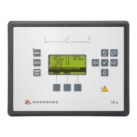
- Page 230 Blinking: Voltage higher than dead bus limit (parameter 5820) but voltage or frequency are not in range. On: Voltage / frequency in operating range. Display / main screen Fig. 100: Main screen (example) The display shows context-sensitive softkey symbols, measuring values, operation modes and alarms. LS-5 v2 Series 37650...
- Page 231 5.2.1/B) permit navigation between screens, levels and functions as well as configuration and operation. Softkey Caption Description symbol Increase Increase value. Decrease Decrease value. Help Access help screen. Toggle Toggle between the configurable elements. Reset Reset the maximum value display. 37650 LS-5 v2 Series...
- Page 232 Indicates that value is part of system A decoupling. thresholds Various screens Variable is TRUE (LogicsManager). The bit is enabled (CAN interface). Relay activated (Discrete outputs) Variable is FALSE (LogicsManager). The bit is disabled (CAN interface). Relay deactivated (Discrete outputs) LS-5 v2 Series 37650...
- Page 233 Released 5 Operation 5.2 Front Panel Access Menu structure Fig. 102: Menu structure 37650 LS-5 v2 Series...
- Page 234 Released 5 Operation 5.2 Front Panel Access Menu structure "Parameter" Fig. 103: Menu structure - Parameter LS-5 v2 Series 37650...
- Page 235 5.2 Front Panel Access Menu structure "Main menu" Fig. 104: Menu structure - Main menu The following chapters list notes on specific menu screens. For information on standard softkeys and status symbols refer to ╚═▷ “5.2.1 Basic Navigation”. 37650 LS-5 v2 Series...
-
Page 236: Parameter Setting Screens
Use the following buttons to change to a sub-menu screen. Sub-menu entries are only displayed if the required or a higher code level is set. Symbol/Button Description Scroll up one row. Scroll down one row. Change to the selected sub-menu screen. LS-5 v2 Series 37650... -
Page 237: Value Setting Screens
Use the following buttons in a value setting screen to select, change and confirm a setting. Button/Softkey Description Select previous digit of selected value. Select next digit of selected value. Increase selected value. Decrease selected value. 37650 LS-5 v2 Series... -
Page 238: Logicsmanager Setting Screens
Scroll up one command variable within section. Scroll down one command variable within section. Navigate to next command variable section Toggle between the configurable elements. Confirm the configured option of the selected LogicsManager parameter. Show help screen (displays logical operators) LS-5 v2 Series 37650... -
Page 239: Main Menu Screens
The voltage display softkey on the main screen changes the type of voltage display (1st row). The following table illustrates what voltage values for system A and system B are available depending on the configured measurement type: 37650 LS-5 v2 Series... - Page 240 Symbol Monitoring Displayed at parameter setting (lower 3Ph4W 3Ph4WOD 3Ph3W 1Ph2W 1Ph3W left) System A voltage Notes System A System A voltage and system A frequency are frequency identical to page one System B voltage Notes LS-5 v2 Series 37650...
-
Page 241: Alarm List
Acknowledgment is only possible, if the alarm condition is no longer present. If the Alarm LED is still flashing (an alarm is present, which has not yet been acknowledged as 'Seen'), this softkey resets the horn and acknowledges the alarm as 'Seen'. 37650 LS-5 v2 Series... -
Page 242: System A
Fig. 113: Slave pointer system A screen (example) Displays the measured and the maximum AC current system A. Symbol/Button Description Reset the maximum value display. 5.2.3.4 System B Fig. 114: Measured values system B screen (example) Displays all measured AC values system B. LS-5 v2 Series 37650... -
Page 243: System Angles
Reset the maximum value display. 5.2.3.5 System Angles Fig. 116: System angles screen (example) Displays the real system angles between system A and system B without phase angle compensation (parameter 8824). 5.2.3.6 Synchroscope Fig. 117: Synchroscope screen (example) 37650 LS-5 v2 Series... -
Page 244: Logicsmanager Conditions
Fig. 119: Command variables screen (example) Symbol/Button Description Select the highlighted command variable group and display the state of the command variables in this group. Variable is TRUE. Variable is FALSE. LS-5 v2 Series 37650... -
Page 245: Event History
Fig. 121: States easYgen screen (example) This screen displays the states of the easYgen devices. Status symbols Symbol Description STOP operating mode. MANUAL operating mode. AUTOMATIC operating mode. Breaker open (GCB). Breaker closed (GCB). Segment number. Device number. 37650 LS-5 v2 Series... -
Page 246: States
5.2.3.11 Segments LS-5 Fig. 123: Segments LS-5 screen (example) This screen displays the segments of the LS-5 devices. Status symbols Symbol Description "A": System A side Segment numbers and breaker open. Segment numbers and breaker closed. LS-5 v2 Series 37650... -
Page 247: 5.2.3.12 Discrete Inputs/Outputs
N.C., it reacts on the de-energized state. Type Symbol State Input energized de-energized Output relay activated relay de-activated 5.2.3.13 Analog Input Fig. 125: Battery voltage screen (example) This screen displays the battery voltage. 37650 LS-5 v2 Series... -
Page 248: 5.2.3.14 System A Decoupling Thresholds
Decrements decoupling value setpoint. When pressing the button permanent the value changes faster. Symbol Description Indicates parameters that are part of the system A decoupling configuration. The buttons navigate through the following thresholds which can be adjusted: LS-5 v2 Series 37650... - Page 249 (╚═▷ “4.3.1.8 System A Undervoltage (Level 1 & 2) ANSI# 27”) Fig. 130: Decoupling phase shift (example) The following values are treated similar: • Phase shift 3-phase (╚═▷ “4.3.1.3 Phase Shift”) • Phase shift 1-phase (╚═▷ “4.3.1.3 Phase Shift”) • Df/dt (╚═▷ “4.3.1.3 Phase Shift”) 37650 LS-5 v2 Series...
-
Page 250: Test System A Decoupling (Vde-Ar-N 4105)
Description Execute Opens immediately the breaker that is configured for decoupling. This function is independent from the breaker status and is active for 1 sec. 5.2.3.16 Counters Fig. 133: CBA and CBB close counters screen (example) LS-5 v2 Series 37650... -
Page 251: 5.2.3.17 Actual Date And Time
Fig. 136: Actual date and time screen (example) Displays the actual date and time. Format is: YYYY-MMM-DD and hh:mm:ss 5.2.3.18 Version Fig. 137: Version screen (example) Displays the serial number of the unit and the firm- and software P/N, version, and revision. 37650 LS-5 v2 Series... -
Page 252: Change Operating Modes
Fig. 138: LS-522 v2, 2breaker front panel Mode button: MAN Mode button: AUTO 4 .. 6 Soft buttons, current function displayed with the according symbol on screen; e.g. breaker A (4) or breaker B (6) OPEN/CLOSE LS-5 v2 Series 37650... -
Page 253: Operating Mode Manual
CBA will be closed at first. Additionally the closing request for CBA stops an active breaker closing from CBB. Fig. 139: LS-5x2 v2 Main screen in operating mode MANUAL (example) Synchroscope The synchronization of the breakers can be initiated via softkeys. 37650 LS-5 v2 Series... -
Page 254: Operating Mode Automatic
In this case, the following proceeding helps to restore the desired language. The default setting is English. Change Language Setting ⚙ In order to change the language setting, press the softkeys in the following order: ᐳ LS-5 v2 Series 37650... - Page 255 "Language / clock config." screen. 4. ▷ Press softkey twice to edit the language setting. 5. ▷ Press softkey to select the desired language. 6. ▷ Press softkey once to commit the language setting. The desired display language is restored. ▶ 37650 LS-5 v2 Series...
-
Page 256: Application
The control units can be used stand-alone (╚═▷ “6.2 Setup Stand-Alone Applications (Mode A01)”) or common applications with Woodward easYgen-3400/3500 or easYgen-3400XT/3500XT genset control units (╚═▷ “6.3 Setup easYgen & Slave LS-5x2 Applications (Mode A05)”,... -
Page 257: Ls-5X2 & Easygen-3400/3500 Or Easygen-3400Xt/3500Xt: Common Application Modes
• Measuring of active and reactive power on system A. • Measuring of phase angle system A to system B. • Recognition of segments within the easYgen / LS-5 system. • Dead bus arbitration with other easYgen and LS-5. 37650 LS-5 v2 Series... -
Page 258: Easygen-3400/3500 Or Easygen-3400Xt/3500Xt View
• Indicating the sum of active and reactive power sent from all 'Mains'-LS-5 in the own segment. • Regulating Import/Export power with the sum of active and reactive power sent from all 'Mains'-LS-5 in the own segment. LS-5 v2 Series 37650... -
Page 259: Setup Stand-Alone Applications (Mode A01)
PLC. The PLC receives all measurement values (voltages, current, power, phase angle) via communication interface to run closed loop synchronization. Each breaker can be individually opened and closed, whereby the LS-5 recognizes to “close only” or to synchronize. 37650 LS-5 v2 Series... - Page 260 • Personnel: Qualified electrician 1. ▷ For a mains decoupling function, connect the system A measurement on the mains busbar. 2. ▷ Setup the PLC to act as master and to monitor the functionality of the communication interface. ⚙ Configure LS-5 LS-5 v2 Series 37650...
- Page 261 • To configure the open command CBA, the LogicsManager equation "Open CBA immed." can be modified. Navigate to [Configuration / Application config. / Breakers config. / Configure CBA / Open CBA immed.] and enter the desired arguments. 37650 LS-5 v2 Series...
-
Page 262: Setup Easygen & Slave Ls-5X2 Applications (Mode A05)
LogicsManager equations in the LS-5x2. Therefore 6 CB control flags are sent from the easYgen-3000XT to the LS-5x2. They have the following meaning: Name Function 28.01 Command 1 to LS5 easYgen (OR) Open and close MCB 28.02 Command 2 to LS5 easYgen (OR) LS-5 v2 Series 37650... - Page 263 The L-GGBMCB mode does not allow any other segmenting as demonstrated in the drawing above. If further segments are desired, the easYgen and the LS-5 must be configured to the free LS-5 mode: easYgen and LS-5 37650 LS-5 v2 Series...
-
Page 264: Setup Easygen & Independent Ls-5X2 Applications (Mode A02)
The operating mode MANUAL in the LS-5 is supported and provides the operator with the option to manually force a close or open of the breaker. For this purpose the LS-5 provides an operating mode button and a softkey to close and open the breaker. LS-5 v2 Series 37650... - Page 265 A rule of thumb is that the total amount of easYgens and LS-5s shall never expire 48 devices. To be on the safe side please discuss the possible risks with the Woodward Sales Support. General notes The LS-5 is expecting at least one easYgen device in the system.
- Page 266 CAN bus Node-ID number To communicate via the CAN bus it is necessary to configure all connected controls with a unique CAN bus Node-ID number (parameter 8950). Usually the same number like the device ID number is taken. LS-5 v2 Series 37650...
-
Page 267: General Functions
Unless special numbering conventions are required, count up continuously from left to right or right to left. 7. ▷ Draw the measurement system A and B of the single LS-5 into the single line diagram according to the definitions in ╚═▷ “6.3.1 Introduction”. 37650 LS-5 v2 Series... -
Page 268: Setup Mains Measurement With Easygen
Change of frequency 3058 Overfrequency level 1 2850 Underfrequency level 1 2900 Overfrequency level 2 2856 Underfrequency level 2 2906 Overvoltage level 1 2950 Undervoltage level 1 3000 Overvoltage level 2 2956 Undervoltage level 2 3006 LS-5 v2 Series 37650... -
Page 269: Setup Mains Decoupling With Easygen
When the mains decoupling over GCB is required, refer to ╚═▷ “6.4.2.3 Setup Mains Decoupling With easYgen”. The LS-5(s) which are responsible for the mains breakers take over the mains monitoring and execute the decoupling function. 37650 LS-5 v2 Series... - Page 270 Multiple LS-5s on different mains incoming points should have the same setting. Navigate to [SyA. Decoupling] and configure the LogicsManager equation "Enable SyA 5. ▷ dec.". The following steps show two different configuration examples. 6. ▷ LogicsManager configuration example 1 LS-5 v2 Series 37650...
- Page 271 LogicsManager configuration example 2 7. ▷ Fig. 146: LogicsManager configuration example 2 The mains decoupling function is enabled, if a "Test" key switch is activated. This helps to perform a mains decoupling test without any generator running. 37650 LS-5 v2 Series...
-
Page 272: Setup Run-Up Synchronization In Ls-5 Mode
⚙ 1. ▷ The easYgen(s) monitors the configured segment(s) whether it is in operation range. 2. ▷ If minimum one segment is recognized as being out of operating range, the generator starts after the emergency run delay time. LS-5 v2 Series 37650... - Page 273 Navigate to [Configuration / Monitoring config. / System A]. 2. ▷ Navigate to [Operating voltage / frequency] and configure the operating range for voltage. Navigate to [Operating voltage / frequency] and configure the operating range for 3. ▷ frequency. 4. ▷ Fig. 147: LogicsManager configuration 37650 LS-5 v2 Series...
- Page 274 "LM inhibit emerg.run", "Break emerg. in critical mode" according to your application. Configure the emergency run segments in each easYgen. They can differ between 3. ▷ easYgens or easYgen groups. ▶ Fig. 148: Segment configuration in ToolKit LS-5 v2 Series 37650...
-
Page 275: Setup Manual Breaker Control In Ls-5 Mode
In the example an 'acknowledge' alarm command could be a general flag which would be taken from the OR'ed source. A special close command in the example could come from a specific easYgen and must be therefore not taken from the OR'ed list. 37650 LS-5 v2 Series... -
Page 276: Setup Ls-5 Flags From Ls-5 To Ls-5 And Easygen
LS-5 and easYgen devices. Each LS-5 sends five flags over the CAN interface. The system allows to inform or to command something to other units. In the example the 'acknowledge' command can be sent to all other units to reset alarms. All bits are individual. LS-5 v2 Series 37650... - Page 277 Released 6 Application 6.4 Setup easYgen & Independent LS-5x2 Applications (Mode A02) Fig. 150: LS-5 information transport to LS-5 and easYgen 37650 LS-5 v2 Series...
-
Page 278: H-Configuration With Two Easygen And Two Incoming Mains And Tie-Breaker
(MCB) and with its CBB on a group breaker (GGB). The LS-5x2 could operate an ATS, a Changeover Panel or two separate breakers to fulfill it. Generator mains parallel operation is also possible. A tie-breaker is located between the both generator segments. LS-5 v2 Series 37650... - Page 279 Number all CAN Node-IDs (usually the same as the device number). 5. ▷ Number all segments according to the definitions in ╚═▷ “Segment number”. Unless special numbering conventions are required, count up continuously from left to right or right to left. 37650 LS-5 v2 Series...
- Page 280 The GCB breaker commands are connected to the according easYgen. 5. ▷ The easYgen CAN bus #3 is connected to the CAN bus of the LS-5. 6. ▷ ⚙ Configure LS-5x2 (incoming mains, Changeover Panel) ᐳ • Personnel: User LS-5 v2 Series 37650...
- Page 281 Incorrect settings may cause erratic system behavior and damage to the involved components . • Set the values carefully and double check with a voltmeter at the according breaker. Configure the breaker close and/or open relay(s) according to your MCB (CBA). 8. ▷ 37650 LS-5 v2 Series...
- Page 282 • Control bit 2: switch load 1 to generator 14. ▷ To configure the LogicsManager in regards to close and open commands for the MCB (CBA) and GGB (CBB) navigate to [Configuration / Application config / Breakers config. / Breaker transition mode]. LS-5 v2 Series 37650...
- Page 283 1 is sent by the PLC. 18. ▷ To configure the LogicsManager in regards to close and open commands for the MCB (CBA) and GGB (CBB) navigate to [Configuration / Application config / Breakers config. / Configure CBB]. 37650 LS-5 v2 Series...
- Page 284 2. ▷ Enter the Node-IDs (usually the same like device ID). 3. ▷ Navigate to [Configuration / Application config / Segment config.] and configure the 4. ▷ following parameters: Parameter Value Segment No. Sy.A 8810 Segment No. Sy.B 8811 LS-5 v2 Series 37650...
- Page 285 5820 As required Navigate to [Configuration / Application config / Breakers config. / Configure CBA / 10. ▷ Connect synchronous mains] and set the following parameters: Parameter Value Connect synchronous mains 8820 Max. phase angle 8821 20° 37650 LS-5 v2 Series...
- Page 286 • The LM equation opens the tie breaker with unloading, if the remote control bit 1 is sent by the PLC. The unloading of the tie-breaker is only executed, if one side contains a variable system. Otherwise the open command is given without unloading. LS-5 v2 Series 37650...
- Page 287 • The LM equation gives the release for close CBA, if the remote control bit 3 is sent by the PLC AND the CBA has no closure failure AND the system A measurement detects no phase rotation error. 37650 LS-5 v2 Series...
- Page 288 Underfrequency level 2 2906 Overvoltage level 1 2950 Undervoltage level 1 3000 Overvoltage level 2 2956 Undervoltage level 2 3006 Mains voltage increase 8806 7. ▷ When tapping voltages over power transformer, phase angle compensation may be required. LS-5 v2 Series 37650...
- Page 289 In this setup each easYgen device provides six control bits for sending information to the LS-5. These bits can be used as command variables in the LS-5 to initiate i.e. an alarm acknowledgement or to release the mains decoupling. 37650 LS-5 v2 Series...
-
Page 290: Setup Vde-Ar-N 4105 Applications
Some typical applications are shown below. For more information please refer to the according FNN VDE-AR-N 4105 document. To help in these specific applications Woodward provides also an application note with more details and how to configure the devices. -
Page 291: Multiple Easygen-3500Xt (Mode Gcb/L-Ggbmcb) With Ls-522 As Separate Mains Decoupling Device
The LS-522 contains the counter part of mains decoupling function in regards of FNN VDE- AR-N 4105 needs. It operates the GGB and the MCB according to the application mode 'L- GGBMCB'. This mode is only supported by the easYgen-3500XT version 1.13 and higher. 37650 LS-5 v2 Series... -
Page 292: Breaker Feedback Security Procedure
CBA and CBB to decide, whether a breaker must be synchronized or can be closed directly. So for example if the CBA is open and the dead busbar closure CBB is enabled, the CBB will be closed onto the dead load busbar. LS-5 v2 Series 37650... -
Page 293: Function
System A System B Voltage relay LS-5x2 Fig. 160: Example: The voltage relay informs by DI 2 about the load busbar condition. In this proposal the discrete input 2 is used for the load busbar signal. 37650 LS-5 v2 Series... - Page 294 The failure flag shall block both breaker closures generally. Two alarms have to be configured: • Free alarm 1 -> Blocking CBA closure with alarm text “Dead bus failure” • Free alarm 2 -> Blocking CBB closure with the same alarm text “Dead bus failure” LS-5 v2 Series 37650...
- Page 295 Fig. 163: Toolkit: Configuration of two alarms to block both breakers (example) • Alarm class D: The breaker CBA is opened immediately or will be not closed • Alarm class F: The breaker CBB is opened immediately or will be not closed 37650 LS-5 v2 Series...
-
Page 296: Interfaces And Protocols
LS-51x Fig. 164: LS-51x interfaces LS-52x Fig. 165: LS-52x interfaces The LS-5 (╚═▷ Fig. 164/╚═▷ Fig. 165) provides the following interfaces, which are supporting different protocols. Figure Interface Protocol Modbus, ToolKit Service Port (USB/RS-232) RS-485 Modbus LS-5 v2 Series 37650... -
Page 297: Can Interfaces
LS-5s shall never expire 48 devices. To be on the safe side please discuss the possible risks with the Woodward Sales Support. 7.1.3 Serial Interfaces 7.1.3.1 Service Port (RS-232/USB) The Woodward specific service port can be used to extend the interfaces of the controller. 37650 LS-5 v2 Series... -
Page 298: Rs-485 Interface
The extended serial interface provides a Modbus as well as the Woodward ToolKit protocol. Fig. 167: Service Port The service port can be only used in combination with an optional Woodward direct configuration cable (DPC), which includes a converter box to provide either an USB or a RS-232 interface. -
Page 299: Canopen Protocol
Example: Value 266 = 10A hex of type UNSIGNED16 is transmitted on the bus in two octets, first 0A hex and then 01 hex. SIGNED type data has integers as values. The range is between -2 and 2 -1. The data is shown by the bit sequence of length n. 37650 LS-5 v2 Series... -
Page 300: Modbus Protocol
(PLCs). It has become a de facto standard communications protocol in industry, and is now the most commonly available means of connecting industrial electronic devices. The Woodward controller supports a Modbus RTU Slave module. This means that a Master node needs to poll the controller slave node. - Page 301 450001. On this address range it is possible to do block reads from 1 up to 128 Modbus registers at a time. Modbus read Description Multiplier Units addresses 450001 Protocol-ID, always 5300 – 450002 Scaling Power (16 bits) Exponent 10x W (5;4;3;2) ....... 37650 LS-5 v2 Series...
- Page 302 40001 and ends at 450000. You can always access only one parameter of the system in this address range. The Modbus address can be calculated depending on the parameter ID as illustrated below: LS-5 v2 Series 37650...
- Page 303 Modbus registers which depends on the data type (UNSIGNED 8, INTEGER 16, etc.). Types Modbus registers UNSIGNED 8 UNSIGNED 16 INTEGER 16 UNSIGNED 32 INTEGER 32 LOGMAN TEXT/X Tab. 35: Data types 37650 LS-5 v2 Series...
- Page 304 Address length example Parameter 1766 SyA. rated voltage is a two byte data type, parameter 1754 SyA. rated current is a one byte data type: Fig. 171: ModScan to handle 1 and 2 bytes data types LS-5 v2 Series 37650...
-
Page 305: Technical Specifications
Rated voltage phase – ground 150 Vac Rated surge voltage (V 2.5 kV surge 480 V Measuring voltage Rated value (V 277/480 Vac rated Maximum value (V max. 346/600 Vac Rated voltage phase – ground 300 Vac 37650 LS-5 v2 Series... -
Page 306: Ambient Variables
Full supply range Input capacitance LS-512: 660 µF LS-522: 660 µF 8.1.3 Inputs/Outputs Discrete inputs Discrete inputs Galvanically isolated Input range (Vcont. dig. input) Rated voltage 12/24 Vdc (8 to 40.0 Vdc) Input resistance approx. 20 kΩ LS-5 v2 Series 37650... -
Page 307: Interface
≤1% of full scale 8.1.4 Interface Service Port interface (RS232/USB) Service Port interface Not isolated Proprietary interface Connect only with Woodward DPC cable RS-485 interface RS-485 interface Galvanically isolated Insulation voltage (continuously) 100 Vac Insulation test voltage (≤ 5 s) -
Page 308: Battery
In general, appropriate local guidelines and regulations must be followed when disposing of electrical devices and batteries. Type Lithium Life span (operation without power supply) approx. 5 years Battery field replacement Not allowed 8.1.6 Housing Housing type Type Plastic easYpack Sheet metal Custom LS-5 v2 Series 37650... -
Page 309: Approvals
8.1.8 Generic Note Accuracy Referred to full scale value Environmental Data Vibration Frequency range - sine sweep 5 Hz to 100 Hz Acceleration Standards EN 60255-21-1 (EN 60068-2-6, Fc) Lloyd’s Register, Vibration Test2 SAEJ1455 Chassis Data 37650 LS-5 v2 Series... -
Page 310: Accuracy
0.1 % (of 85 Hz) 5 % (of PT secondary voltage setting) System B Voltage Wye system A / system 0 to 650 kV 1.5 % (of PT secondary 1 % (of 120/480 V) voltage setting) LS-5 v2 Series 37650... - Page 311 The reference conditions for measuring the accuracy are listed below. Input voltage Sinusoidal rated voltage Input current Sinusoidal rated current Frequency Rated frequency +/- 2 % Power supply Rated voltage +/- 2 % Power factor (cos φ) 1.00 Ambient temperature 23 °C +/- 2 K 37650 LS-5 v2 Series...
- Page 312 Released 8 Technical Specifications 8.3 Accuracy Warm-up period 20 minutes LS-5 v2 Series 37650...
-
Page 313: Appendix
Released 9 Appendix 9.1 Characteristics Appendix Characteristics 9.1.1 Triggering Characteristics Two-level overshoot monitoring Fig. 174: Two-level overshoot monitoring In the monitor above this triggering characteristic is used: System A overvoltage, System A overfrequency, Battery overvoltage, ... 37650 LS-5 v2 Series... - Page 314 Released 9 Appendix 9.1 Characteristics Two-level undershoot monitoring Fig. 175: Two-level undershoot monitoring In the monitor above this triggering characteristic is used: System A undervoltage, System A underfrequency, Battery undervoltage, ... LS-5 v2 Series 37650...
-
Page 315: Data Protocols
Protocol ID, always 5301 LS-5x1 v2, LS-5x2 v2 3,4,5,6 System A total reactive power LS-5x1 v2, LS-5x2 v2 System A power factor (cos.phi) 0.001 LS-5x1 v2, LS-5x2 v2 3,4,5,6 System A average wye voltage LS-5x1 v2, LS-5x2 v2 37650 LS-5 v2 Series... - Page 316 LS-5x1 v2, LS-5x2 v2 Relay-Output 3 Mask: 2000h LS-5x1 v2, LS-5x2 v2 Relay-Output 4 Mask: 1000h LS-5x1 v2, LS-5x2 v2 Relay-Output 5 Mask: 0800h LS-5x1 v2, LS-5x2 v2 Relay-Output 6 Mask: 0400h LS-5x1 v2, LS-5x2 v2 LS-5 v2 Series 37650...
- Page 317 Mask: 4000h internal Mask: 8000h 3,4,5,6 System A current 1 0.001 LS-5x1 v2, LS-5x2 v2 10110 Battery voltage LS-5x1 v2, LS-5x2 v2 3,4,5,6 System A current 2 0.001 LS-5x1 v2, LS-5x2 v2 10146 internal Mask: 0001h 37650 LS-5 v2 Series...
- Page 318 LS-5x2 v2 00.45 LM Relay 5 Mask: 0800h LS-5x1 v2, LS-5x2 v2 00.46 LM Relay 6 Mask: 0400h LS-5x1 v2, LS-5x2 v2 internal Mask: 0200h internal Mask: 0100h internal Mask: 0080h internal Mask: 0040h internal Mask: 0020h LS-5 v2 Series 37650...
- Page 319 LS-5x2 v2 internal Mask: 0001h 3,4,5,6 System A voltage L1-N LS-5x1 v2, LS-5x2 v2 10148 internal Mask: 8000h internal Mask: 4000h internal Mask: 2000h internal Mask: 1000h 04.04 Lamp test Mask: 0800h LS-5x1 v2, LS-5x2 v2 37650 LS-5 v2 Series...
- Page 320 00.36 LM Internal flag 15 Mask: 0008h LS-5x1 v2, LS-5x2 v2 00.37 LM Internal flag 16 Mask: 0004h LS-5x1 v2, LS-5x2 v2 internal Mask: 0002h internal Mask: 0001h 3,4,5,6 System A voltage L2-N LS-5x1 v2, LS-5x2 v2 LS-5 v2 Series 37650...
- Page 321 Mask: 0008h 00.38 LM Synchronization mode CHECK Mask: 0004h LS-5x1 v2, LS-5x2 v2 00.39 LM Synchronization mode PERMISSIVE Mask: 0002h LS-5x1 v2, LS-5x2 v2 00.40 LM Synchronization mode RUN Mask: 0001h LS-5x1 v2, LS-5x2 v2 37650 LS-5 v2 Series...
- Page 322 State Discrete Input 3 latched Mask: 0400h LS-5x1 v2, LS-5x2 v2 State Discrete Input 2 latched Mask: 0200h LS-5x1 v2, LS-5x2 v2 State Discrete Input 1 latched Mask: 0100h LS-5x1 v2, LS-5x2 v2 internal Mask: 0080h LS-5 v2 Series 37650...
- Page 323 Mask: 0002h LS-5x2 v2 internal Mask: 0001h 3,4,5,6 System B total reactive power LS-5x2 v2 04.59 Remote control bit 16 Mask: 8000h LS-5x1 v2, LS-5x2 v2 04.58 Remote control bit 15 Mask: 4000h LS-5x1 v2, LS-5x2 v2 37650 LS-5 v2 Series...
- Page 324 Mask: 1000h internal Mask: 0800h internal Mask: 0400h internal Mask: 0200h internal Mask: 0100h internal Mask: 0080h internal Mask: 0040h internal Mask: 0020h internal Mask: 0010h 08.02 Battery overvoltage threshold 2 Mask: 0008h LS-5x1 v2, LS-5x2 v2 LS-5 v2 Series 37650...
- Page 325 Mask: 0020h internal Mask: 0010h internal Mask: 0008h internal Mask: 0004h internal Mask: 0002h internal Mask: 0001h 3,4,5,6 System B voltage L1-N LS-5x1 v2, LS-5x2 v2 1791 internal Mask: 8000h internal Mask: 4000h internal Mask: 2000h 37650 LS-5 v2 Series...
- Page 326 Counter Clock Wise (CCW, reverse, left turn) 02.15 System B phase rotation Mask: 0040h LS-5x1 v2, LS-5x2 v2 Clock Wise (CW, forward, right turn) internal Mask: 0020h internal Mask: 0010h internal Mask: 0008h internal Mask: 0004h internal Mask: 0002h internal Mask: 0001h LS-5 v2 Series 37650...
- Page 327 LS-5x1 v2, mismatch LS-5x2 v2 reserved Mask: 0400h internal Mask: 0200h internal Mask: 0100h internal Mask: 0080h internal Mask: 0040h internal Mask: 0020h internal Mask: 0010h 08.17 Number of member mismatch Mask: 0008h LS-5x1 v2, LS-5x2 v2 37650 LS-5 v2 Series...
- Page 328 Mask: 8000h LS-5x1 v2, LS-5x2 v2 02.24 System B is dead Mask: 4000h LS-5x1 v2, LS-5x2 v2 02.25 Mains parallel operation Mask: 2000h LS-5x1 v2, LS-5x2 v2 System B mains connected Mask: 1000h LS-5x1 v2, LS-5x2 v2 LS-5 v2 Series 37650...
- Page 329 LS-5x1 v2, LS-5x2 v2 Syst. B phase rotation CW (for ToolKit) Mask: 0002h LS-5x1 v2, LS-5x2 v2 Syst. B phase rotation CCW (for ToolKit) Mask: 0001h LS-5x1 v2, LS-5x2 v2 10133 internal Mask: 8000h internal Mask: 4000h 37650 LS-5 v2 Series...
- Page 330 Mask: 0008h LS-5x1 v2, LS-5x2 v2 24.33 Immediate open CB A Mask: 0004h LS-5x1 v2, LS-5x2 v2 24.32 Open CB A Mask: 0002h LS-5x1 v2, LS-5x2 v2 24.31 Enable mains decoupling Mask: 0001h LS-5x1 v2, LS-5x2 v2 LS-5 v2 Series 37650...
- Page 331 Mask: 0080h LS-5x1 v2, LS-5x2 v2 07.25 System A decoupling Mask: 0040h LS-5x1 v2, LS-5x2 v2 internal Mask: 0020h internal Mask: 0010h 07.26 System A voltage asymmetry (with Mask: 0008h LS-5x1 v2, negative sequence) LS-5x2 v2 37650 LS-5 v2 Series...
- Page 332 Mask: 4000h internal Mask: 2000h internal Mask: 1000h internal Mask: 0800h internal Mask: 0400h internal Mask: 0200h internal Mask: 0100h internal Mask: 0080h internal Mask: 0040h internal Mask: 0020h internal Mask: 0010h internal Mask: 0008h LS-5 v2 Series 37650...
-
Page 333: Data Protocol 5302 (Basic Visualization)
The following operation modes are supported by the LS-5x2 v2 only: 13256 = Unloading CB B 13261 = CB B - CB A delay 13262 = CB A - CB B delay 13259 = Synchronization CB B 37650 LS-5 v2 Series... - Page 334 Mask: 0001h internal Mask: 0002h internal Mask: 0004h internal Mask: 0008h internal Mask: 0010h internal Mask: 0020h internal Mask: 0040h internal Mask: 0080h 28.01 Command to CB-control 1 (OR'ed) Mask: 0100h LS-5x1 v2, LS-5x2 v2 LS-5 v2 Series 37650...
- Page 335 LS-5x2 v2 internal Mask: 0400h 04.05 Acknowledge was executed Mask: 0800h LS-5x1 v2, LS-5x2 v2 01.09 Shutdown alarm active (alarm C-F) Mask: 1000h LS-5x1 v2, LS-5x2 v2 internal Mask: 2000h internal Mask: 4000h internal Mask: 8000h 37650 LS-5 v2 Series...
- Page 336 00.06 LM Internal flag 6 Mask: 0400h LS-5x1 v2, LS-5x2 v2 00.07 LM Internal flag 7 Mask: 0200h LS-5x1 v2, LS-5x2 v2 00.08 LM Internal flag 8 Mask: 0100h LS-5x1 v2, LS-5x2 v2 internal Mask: 0080h LS-5 v2 Series 37650...
- Page 337 Mask: 0004h internal Mask: 0002h internal Mask: 0001h 3,4,5,6 System A voltage L2-L3 LS-5x1 v2, LS-5x2 v2 10150 internal Mask: 8000h internal Mask: 4000h internal Mask: 2000h internal Mask: 1000h internal Mask: 0800h internal Mask: 0400h 37650 LS-5 v2 Series...
- Page 338 Mask: 0010h internal Mask: 0008h internal Mask: 0004h 01.11 New alarm triggered Mask: 0002h LS-5x1 v2, LS-5x2 v2 internal Mask: 0001h 3,4,5,6 System A voltage L3-L1 LS-5x1 v2, LS-5x2 v2 10162 internal Mask: 8000h internal Mask: 4000h LS-5 v2 Series 37650...
- Page 339 Mask: 0008h LS-5x1 v2, LS-5x2 v2 Alarm class C latched Mask: 0004h LS-5x1 v2, LS-5x2 v2 Alarm class B latched Mask: 0002h LS-5x1 v2, LS-5x2 v2 Alarm class A latched Mask: 0001h LS-5x1 v2, LS-5x2 v2 37650 LS-5 v2 Series...
- Page 340 System B power factor 0.001 LS-5x2 v2 3,4,5,6 System B total active power AC measurement LS-5x2 v2 10137 internal Mask: 8000h internal Mask: 4000h internal Mask: 2000h internal Mask: 1000h internal Mask: 0800h internal Mask: 0400h LS-5 v2 Series 37650...
- Page 341 LS-5x1 v2, LS-5x2 v2 04.46 Remote control bit 3 Mask: 0004h LS-5x1 v2, LS-5x2 v2 04.45 Remote control bit 2 Mask: 0002h LS-5x1 v2, LS-5x2 v2 04.44 Remote control bit 1 Mask: 0001h LS-5x1 v2, LS-5x2 v2 37650 LS-5 v2 Series...
- Page 342 LS-5x1 v2, LS-5x2 v2 (Based on system A voltage window) internal Mask: 0800h internal Mask: 0400h 02.10 System A frequency in range Mask: 0200h LS-5x1 v2, LS-5x2 v2 (Based on system A frequency window) internal Mask: 0100h LS-5 v2 Series 37650...
- Page 343 Mask: 0010h internal Mask: 0008h internal Mask: 0004h internal Mask: 0002h internal Mask: 0001h 3,4,5,6 System B voltage L2-L3 LS-5x1 v2, LS-5x2 v2 1792 internal Mask: 8000h internal Mask: 4000h internal Mask: 2000h internal Mask: 1000h 37650 LS-5 v2 Series...
- Page 344 Mask: 0100h internal Mask: 0080h internal Mask: 0040h internal Mask: 0020h internal Mask: 0010h internal Mask: 0008h internal Mask: 0004h internal Mask: 0002h internal Mask: 0001h 3,4,5,6 System B voltage L3-L1 LS-5x1 v2, LS-5x2 v2 LS-5 v2 Series 37650...
- Page 345 LS-5x2 v2 04.18 Synchronisation CB B procedure is active Mask: 0040h LS-5x2 v2 04.11 Mains settling is active Mask: 0020h LS-5x1 v2, LS-5x2 v2 LS-5x1 v2: Mask: 0010h LS-5x1 v2, LS-5x2 v2 24.39 Isolation switch is open 37650 LS-5 v2 Series...
- Page 346 System B phase rotation CW (ToolKit) Mask: 4000h LS-5x1 v2, LS-5x2 v2 System A phase rotation CCW (ToolKit) Mask: 2000h LS-5x1 v2, LS-5x2 v2 System A phase rotation CW (ToolKit) Mask: 1000h LS-5x1 v2, LS-5x2 v2 internal Mask: 0800h LS-5 v2 Series 37650...
- Page 347 Mask: 0004h internal Mask: 0002h 08.18 CANopen error interface 1 Mask: 0001h LS-5x1 v2, LS-5x2 v2 10191 internal Mask: 8000h internal Mask: 4000h internal Mask: 2000h 24.45 Flag 5 LS 5 Mask: 1000h LS-5x1 v2, LS-5x2 v2 37650 LS-5 v2 Series...
- Page 348 Mask: 0008h internal Mask: 0004h internal Mask: 0002h internal Mask: 0001h 10135 07.06 System A overfrequency threshold 1 Mask: 8000h LS-5x1 v2, LS-5x2 v2 07.07 System A overfrequency threshold 2 Mask: 4000h LS-5x1 v2, LS-5x2 v2 LS-5 v2 Series 37650...
- Page 349 07.15 df/dt (ROCOF) Mask: 0080h LS-5x1 v2, LS-5x2 v2 internal Mask: 0040h 07.28 System A time-dependent voltage Mask: 0020h LS-5x1 v2, LS-5x2 v2 internal Mask: 0010h 07.27 System A voltage increase Mask: 0008h LS-5x1 v2, LS-5x2 v2 37650 LS-5 v2 Series...
-
Page 350: Protocol 6003 (Ls-5 Communication)
• The sequence of the sent messages for TFast = 100 ms (i.e. 0.10 s) is shown in ╚═▷ “Load share bus communication”. • This means that a new message is sent every 50 ms. Time [ms] Sent message Mux # LS-5 v2 Series 37650... - Page 351 Load share bus communication - "fast" refreshed data Byte Function Remark Mux identifier Frequency of connected mains or frequency to Frequency in 00.00 Hz which is to synchronize Phase angle between system A and B Phase angle [1/10°] 37650 LS-5 v2 Series...
- Page 352 A and B ◦ Synchronous mains or segment closing isn't active Variable system Notes 0 = System A The LS-5 informs that the "variable system" is on side A or B. 1 = System B LS-5 v2 Series 37650...
- Page 353 Load share bus communication - "normal" refreshed data Byte Function Remark Mux identifier Not used Logic bit 1 Logic bit 2 Logic bit 3 Logic bit 4 Logic bit 5 Mains settling active Not used Reactive power system A Long [var] 37650 LS-5 v2 Series...
- Page 354 1.2 s for i.e. fast cycle = 100 ms. Mains power measurement valid This means the power of system A is used for mains import/export control Segment number isolation switch Max. 32 nodes possible LS-5 v2 Series 37650...
-
Page 355: Modbus
"Slow 1" Not used 9.2.2 Modbus 9.2.2.1 Data Protocol 5300 (Basic Visualization) Modbus Para- Description Multiplier Units Model meter Modicon Start addr. start addr. (*1) 450001 450000 Protocol-ID, always 5300 – LS-5x1 v2, LS-5x2 37650 LS-5 v2 Series... - Page 356 Address 450003) 450019 450018 System A voltage L3-N scaled defined LS-5x1 v2, LS-5x2 by index 3182 (modicon Address 450003) 450020 450019 System A current 1 scaled defined LS-5x1 v2, LS-5x2 by index 3183 (modicon Address 450004) LS-5 v2 Series 37650...
- Page 357 3182 (modicon Address 450003) 450038 450037 System B voltage L2-N scaled defined LS-5x1 v2, LS-5x2 by index 3182 (modicon Address 450003) 450039 450038 System B voltage L3-N scaled defined LS-5x1 v2, LS-5x2 by index 3182 37650 LS-5 v2 Series...
- Page 358 10202 State display Please refer to (enum.) LS-5x1 v2, LS-5x2 ╚═▷ “9.4.2 Status Messages” an ID description. 450061 450060 8018 Visualization remote and CB-Control internal Mask: 0001h internal Mask: 0002h internal Mask: 0004h internal Mask: 0008h LS-5 v2 Series 37650...
- Page 359 Mask: 0200h LS-5x1 v2, LS-5x2 internal Mask: 0400h 04.05 Acknowledge was executed Mask: 0800h LS-5x1 v2, LS-5x2 01.09 Shutdown alarms are active Mask: 1000h LS-5x1 v2, LS-5x2 (alarm class C-F) internal Mask: 2000h internal Mask: 4000h 37650 LS-5 v2 Series...
- Page 360 Mask: 0040h internal Mask: 0080h 00.08 LM Internal flag 8 Mask: 0100h LS-5x1 v2, LS-5x2 00.07 LM Internal flag 7 Mask: 0200h LS-5x1 v2, LS-5x2 00.06 LM Internal flag 6 Mask: 0400h LS-5x1 v2, LS-5x2 LS-5 v2 Series 37650...
- Page 361 00.37 LM Internal flag 16 Mask: 0004h LS-5x1 v2, LS-5x2 00.36 LM Internal flag 15 Mask: 0008h LS-5x1 v2, LS-5x2 00.35 LM Internal flag 14 Mask: 0010h LS-5x1 v2, LS-5x2 00.34 LM Internal flag 13 Mask: 0020h LS-5x1 v2, LS-5x2 37650 LS-5 v2 Series...
- Page 362 450068 450067 10136 Monitoring analog inputs 08.03 Battery undervoltage Mask: 0001h LS-5x1 v2, LS-5x2 threshold 1 08.01 Battery overvoltage Mask: 0002h LS-5x1 v2, LS-5x2 threshold 1 08.04 Battery undervoltage Mask: 0004h LS-5x1 v2, LS-5x2 threshold 2 LS-5 v2 Series 37650...
- Page 363 02.09 System A voltage in range Mask: 1000h LS-5x1 v2, LS-5x2 (Based on System B voltage window) 02.05 System B voltage and Mask: 2000h LS-5x1 v2, LS-5x2 frequency in range (Ready for operation, 02.03 AND 02.04 are TRUE) 37650 LS-5 v2 Series...
- Page 364 Mask: 0004h internal Mask: 0008h internal Mask: 0010h internal Mask: 0020h 02.15 System B phase rotation Mask: 0040h LS-5x1 v2, LS-5x2 Clock Wise (CW, forward, right turn) 02.14 System B phase rotation Mask: 0080h LS-5x1 v2, LS-5x2 LS-5 v2 Series 37650...
- Page 365 LS-5x2 v2 04.29 Unloading CB A is active Mask: 2000h LS-5x1 v2, LS-5x2 04.41 Breaker Transition Mode Mask: 4000h LS-5x2 v2 Alternative 1 04.42 Breaker Transition Mode Mask: 8000h LS-5x2 v2 Alternative 2 450074 450073 4154 ControlBits2 37650 LS-5 v2 Series...
- Page 366 LS-5x1 v2, LS-5x2 450075 450074 4155 ControlBits3 internal Mask: 0001h internal Mask: 0002h internal Mask: 0004h internal Mask: 0008h internal Mask: 0010h internal Mask: 0020h internal Mask: 0040h internal Mask: 0080h internal Mask: 0100h internal Mask: 0200h LS-5 v2 Series 37650...
- Page 367 LS-5x1 v2, LS-5x2 internal Mask: 2000h internal Mask: 4000h internal Mask: 8000h 450077 450076 10138 Monitoring System B internal Mask: 0001h internal Mask: 0002h internal Mask: 0004h internal Mask: 0008h internal Mask: 0010h internal Mask: 0020h 37650 LS-5 v2 Series...
- Page 368 07.07 System A overfrequency Mask: 4000h LS-5x1 v2, LS-5x2 threshold 2 07.06 System A overfrequency Mask: 8000h LS-5x1 v2, LS-5x2 threshold 1 450079 450078 4138 Monitoring System A 07.30 QV Monitoring step 2 tripped Mask: 0001h LS-5x1 v2, LS-5x2 LS-5 v2 Series 37650...
- Page 369 04.51 Remote control bit 8 Mask: 0080h LS-5x1 v2, LS-5x2 04.52 Remote control bit 9 Mask: 0100h LS-5x1 v2, LS-5x2 04.53 Remote control bit 10 Mask: 0200h LS-5x1 v2, LS-5x2 04.54 Remote control bit 11 Mask: 0400h LS-5x1 v2, LS-5x2 37650 LS-5 v2 Series...
- Page 370 450081 reserved 450083 450082 reserved 450084 450083 reserved 450085 450084 reserved 450086 450085 reserved 450087 450086 reserved 450088 450087 reserved 450089 450088 reserved 450090 450089 reserved Discrete Outputs 450091 450090 10107 Discrete outputs 1 to 6 LS-5 v2 Series 37650...
- Page 371 Mask: 0800h internal Mask: 0400h internal Mask: 0200h internal Mask: 0100h internal Mask: 0080h internal Mask: 0040h Alarm class F latched Mask: 0020h LS-5x1 v2, LS-5x2 Alarm class E latched Mask: 0010h LS-5x1 v2, LS-5x2 37650 LS-5 v2 Series...
- Page 372 Mask: 2000h internal Mask: 1000h 08.33 System A / System B phase Mask: 0800h LS-5x1 v2, LS-5x2 rotation mismatch reserved Mask: 0400h internal Mask: 0200h internal Mask: 0100h internal Mask: 0080h internal Mask: 0040h internal Mask: 0020h LS-5 v2 Series 37650...
- Page 373 LS-5x1 v2, LS-5x2 450103 450102 reserved 450104 450103 4153 ControlBits1 (see above) LS-5x1 v2, LS-5x2 450105 450104 4154 ControlBits2 (see above) LS-5x1 v2, LS-5x2 450106 450105 4155 ControlBits3 (see above) LS-5x1 v2, LS-5x2 450107 450106 reserved 37650 LS-5 v2 Series...
- Page 374 Mask: 0008h internal Mask: 0004h internal Mask: 0002h internal Mask: 0001h 450114 450113 reserved 450115 450114 reserved 450116 450115 reserved 450117 450116 reserved DC Analogue Values Wirebreak 450118 450117 10137 Alarms analog inputs wire break latched (unacknowledged) LS-5 v2 Series 37650...
- Page 375 Mask: 0040h internal Mask: 0080h 29.01 Command to CB-control 1 Mask: 0100h LS-5x1 v2, LS-5x2 29.02 Command to CB-control 2 Mask: 0200h LS-5x1 v2, LS-5x2 29.03 Command to CB-control 3 Mask: 0400h LS-5x1 v2, LS-5x2 37650 LS-5 v2 Series...
- Page 376 450123 450122 Status of Device 3 Generator voltage and frequency ok Mask: 0001h LS-5x1 v2, LS-5x2 Busbar voltage and frequency ok Mask: 0002h LS-5x1 v2, LS-5x2 Mains voltage and frequency ok Mask: 0004h LS-5x1 v2, LS-5x2 LS-5 v2 Series 37650...
- Page 377 29.01 Command to CB-control 1 Mask: 0100h LS-5x1 v2, LS-5x2 29.02 Command to CB-control 2 Mask: 0200h LS-5x1 v2, LS-5x2 29.03 Command to CB-control 3 Mask: 0400h LS-5x1 v2, LS-5x2 29.04 Command to CB-control 4 Mask: 0800h LS-5x1 v2, LS-5x2 37650 LS-5 v2 Series...
- Page 378 Generator voltage and frequency ok Mask: 0001h LS-5x1 v2, LS-5x2 Busbar voltage and frequency ok Mask: 0002h LS-5x1 v2, LS-5x2 Mains voltage and frequency ok Mask: 0004h LS-5x1 v2, LS-5x2 4th system voltage and frequency Mask: 0008h LS-5x1 v2, LS-5x2 LS-5 v2 Series 37650...
- Page 379 29.02 Command to CB-control 2 Mask: 0200h LS-5x1 v2, LS-5x2 29.03 Command to CB-control 3 Mask: 0400h LS-5x1 v2, LS-5x2 29.04 Command to CB-control 4 Mask: 0800h LS-5x1 v2, LS-5x2 29.05 Command to CB-control 5 Mask: 1000h LS-5x1 v2, LS-5x2 37650 LS-5 v2 Series...
- Page 380 Busbar voltage and frequency ok Mask: 0002h LS-5x1 v2, LS-5x2 Mains voltage and frequency ok Mask: 0004h LS-5x1 v2, LS-5x2 4th system voltage and frequency Mask: 0008h LS-5x1 v2, LS-5x2 Busbar 1 dead busbar detection Mask: 0010h LS-5x1 v2, LS-5x2 LS-5 v2 Series 37650...
- Page 381 29.03 Command to CB-control 3 Mask: 0400h LS-5x1 v2, LS-5x2 29.04 Command to CB-control 4 Mask: 0800h LS-5x1 v2, LS-5x2 29.05 Command to CB-control 5 Mask: 1000h LS-5x1 v2, LS-5x2 29.06 Command to CB-control 6 Mask: 2000h LS-5x1 v2, LS-5x2 37650 LS-5 v2 Series...
- Page 382 LS-5x1 v2, LS-5x2 4th system voltage and frequency Mask: 0008h LS-5x1 v2, LS-5x2 Busbar 1 dead busbar detection Mask: 0010h LS-5x1 v2, LS-5x2 Busbar 2 dead busbar detection Mask: 0020h LS-5x1 v2, LS-5x2 internal Mask: 0040h LS-5 v2 Series 37650...
- Page 383 Mask: 0800h LS-5x1 v2, LS-5x2 29.05 Command to CB-control 5 Mask: 1000h LS-5x1 v2, LS-5x2 29.06 Command to CB-control 6 Mask: 2000h LS-5x1 v2, LS-5x2 internal Mask: 4000h internal Mask: 8000h 450134 450133 Status of Device 14 37650 LS-5 v2 Series...
- Page 384 Busbar 1 dead busbar detection Mask: 0010h LS-5x1 v2, LS-5x2 Busbar 2 dead busbar detection Mask: 0020h LS-5x1 v2, LS-5x2 internal Mask: 0040h internal Mask: 0080h 29.01 Command to CB-control 1 Mask: 0100h LS-5x1 v2, LS-5x2 LS-5 v2 Series 37650...
- Page 385 Mask: 1000h LS-5x1 v2, LS-5x2 29.06 Command to CB-control 6 Mask: 2000h LS-5x1 v2, LS-5x2 internal Mask: 4000h internal Mask: 8000h 450137 450136 Status of Device 17 Generator voltage and frequency ok Mask: 0001h LS-5x1 v2, LS-5x2 37650 LS-5 v2 Series...
- Page 386 Busbar 2 dead busbar detection Mask: 0020h LS-5x1 v2, LS-5x2 internal Mask: 0040h internal Mask: 0080h 29.01 Command to CB-control 1 Mask: 0100h LS-5x1 v2, LS-5x2 29.02 Command to CB-control 2 Mask: 0200h LS-5x1 v2, LS-5x2 LS-5 v2 Series 37650...
- Page 387 Mask: 2000h LS-5x1 v2, LS-5x2 internal Mask: 4000h internal Mask: 8000h 450140 450139 Status of Device 20 Generator voltage and frequency ok Mask: 0001h LS-5x1 v2, LS-5x2 Busbar voltage and frequency ok Mask: 0002h LS-5x1 v2, LS-5x2 37650 LS-5 v2 Series...
- Page 388 Mask: 0040h internal Mask: 0080h 29.01 Command to CB-control 1 Mask: 0100h LS-5x1 v2, LS-5x2 29.02 Command to CB-control 2 Mask: 0200h LS-5x1 v2, LS-5x2 29.03 Command to CB-control 3 Mask: 0400h LS-5x1 v2, LS-5x2 LS-5 v2 Series 37650...
- Page 389 450143 450142 Status of Device 23 Generator voltage and frequency ok Mask: 0001h LS-5x1 v2, LS-5x2 Busbar voltage and frequency ok Mask: 0002h LS-5x1 v2, LS-5x2 Mains voltage and frequency ok Mask: 0004h LS-5x1 v2, LS-5x2 37650 LS-5 v2 Series...
- Page 390 29.01 Command to CB-control 1 Mask: 0100h LS-5x1 v2, LS-5x2 29.02 Command to CB-control 2 Mask: 0200h LS-5x1 v2, LS-5x2 29.03 Command to CB-control 3 Mask: 0400h LS-5x1 v2, LS-5x2 29.04 Command to CB-control 4 Mask: 0800h LS-5x1 v2, LS-5x2 LS-5 v2 Series 37650...
- Page 391 Generator voltage and frequency ok Mask: 0001h LS-5x1 v2, LS-5x2 Busbar voltage and frequency ok Mask: 0002h LS-5x1 v2, LS-5x2 Mains voltage and frequency ok Mask: 0004h LS-5x1 v2, LS-5x2 4th system voltage and frequency Mask: 0008h LS-5x1 v2, LS-5x2 37650 LS-5 v2 Series...
- Page 392 29.02 Command to CB-control 2 Mask: 0200h LS-5x1 v2, LS-5x2 29.03 Command to CB-control 3 Mask: 0400h LS-5x1 v2, LS-5x2 29.04 Command to CB-control 4 Mask: 0800h LS-5x1 v2, LS-5x2 29.05 Command to CB-control 5 Mask: 1000h LS-5x1 v2, LS-5x2 LS-5 v2 Series 37650...
- Page 393 Busbar voltage and frequency ok Mask: 0002h LS-5x1 v2, LS-5x2 Mains voltage and frequency ok Mask: 0004h LS-5x1 v2, LS-5x2 4th system voltage and frequency Mask: 0008h LS-5x1 v2, LS-5x2 Busbar 1 dead busbar detection Mask: 0010h LS-5x1 v2, LS-5x2 37650 LS-5 v2 Series...
- Page 394 29.03 Command to CB-control 3 Mask: 0400h LS-5x1 v2, LS-5x2 29.04 Command to CB-control 4 Mask: 0800h LS-5x1 v2, LS-5x2 29.05 Command to CB-control 5 Mask: 1000h LS-5x1 v2, LS-5x2 29.06 Command to CB-control 6 Mask: 2000h LS-5x1 v2, LS-5x2 LS-5 v2 Series 37650...
- Page 395 LS-5x1 v2, LS-5x2 4th system voltage and frequency Mask: 0008h LS-5x1 v2, LS-5x2 Busbar 1 dead busbar detection Mask: 0010h LS-5x1 v2, LS-5x2 Busbar 2 dead busbar detection Mask: 0020h LS-5x1 v2, LS-5x2 internal Mask: 0040h 37650 LS-5 v2 Series...
- Page 396 450165 450164 reserved 450166 450165 reserved 450167 450166 reserved 450168 450167 reserved 450169 450168 reserved 450170 450169 reserved 450171 450170 reserved 450172 450171 reserved 450173 450172 reserved 450174 450173 reserved 450175 450174 reserved 450176 450175 reserved LS-5 v2 Series 37650...
- Page 397 System A voltage L3-N LS-5x1 v2, LS-5x2 450215 450214 System A active power L1-N LS-5x1 v2, LS-5x2 450217 450216 System A active power L2-N LS-5x1 v2, LS-5x2 450219 450218 System A active power L3-N LS-5x1 v2, LS-5x2 37650 LS-5 v2 Series...
- Page 398 450254 System B total active power LS-5x2 v2 450257 450256 reserved AC System Values (Long - 32 bits) 450259 450258 reserved 450261 450260 reserved 450263 450262 reserved 450265 450264 reserved 450267 450266 reserved 450269 450268 reserved LS-5 v2 Series 37650...
-
Page 399: Additional Data Identifier
Depending on the application mode of the unit, the number of available relays that may be programmed with the LogicsManager will vary. Two independent time delays are provided for the configured action to take place and be reset. 37650 LS-5 v2 Series... - Page 400 Value {[Cx]} The value [Cx] is passed 1:1. NOT Value {[Cx]} The opposite of the value [Cx] is passed. 0 [False; always "0"] The value [Cx] is ignored and this logic path will always be FALSE. LS-5 v2 Series 37650...
- Page 401 LogicsManager (for example: operating the relays, setting the flags, specification of the automatic functions) is configured as follows: [Ax] = ( ( [C1] & [S1] ) & [O1] & ( [C2] & [S2] ) ) & [O2] & ( [C3] & [S3] ) 37650 LS-5 v2 Series...
-
Page 402: Logical Symbols
"Alarm class D" 9.3.2 Logical Symbols The following symbols are used for the graphical programming of the LogicsManager. The LS-5 displays symbols according to the DIN 40 700 standard by default. Fig. 179: Logical symbols LS-5 v2 Series 37650... -
Page 403: Logical Outputs
3 commands to be included in a logical function. They may be used like "auxiliary flags". Name Function Number Flag 1 Internal flag 1 00.01 Flag 2 Internal flag 2 00.02 Flag 3 Internal flag 3 00.03 Flag 4 Internal flag 4 00.04 37650 LS-5 v2 Series... - Page 404 (frequency, phase, voltage and phase angle), the control will issue a breaker close command. (parameter 5728) Synchronization mode Normal operating mode. The system actively synchronizes and issues breaker 00.40 closure commands. (parameter 5728) LS-5 v2 Series 37650...
- Page 405 LogicsManager; fixed to 'Open CBB' if parameter 3403 is set to "N.O." 00.43 or "N.C." [R3] If this logical output becomes true, the relay output 3 will be activated Relay 4 36/37 Fixed to 'Close CBB' 00.44 [R4] Relay 5 38/39/40 Fixed to 'Open CBA' [R5] 37650 LS-5 v2 Series...
- Page 406 The default value indicates that the CBB close command is active. LED 8 Communication failure (08.17 Missing See LogicsManager "LED 8" 24.58 LS-5) (parameter 12969). The default value indicates that the multi-unit missing members monitoring function (parameter 4060) has tripped. LS-5 v2 Series 37650...
-
Page 407: Logical Command Variables
'LM' means that these logical command variables are the result of a LogicsManager condition. Name Function Note 00.01 LM Flag 1 Internal flag 1 Internal calculation; refer to ╚═▷ “ Internal flags” 00.02 LM Flag 2 Internal flag 2 Internal calculation; refer to ╚═▷ “ Internal flags” 37650 LS-5 v2 Series... - Page 408 00.41 LM Relay 1 (Ready for op.OFF) TRUE, if the LogicsManager condition driving this relay is 00.42 LM Relay 2 fulfilled 00.43 LM Relay 3 00.44 LM Relay 4 00.45 Reserved 00.46 LM Relay 6 LS-5 v2 Series 37650...
-
Page 409: Group 01: Alarm System
(parameter 1756) for horn reset has not exceeded. 9.3.4.3 Group 02: Systems Condition • Systems condition • Logic command variables 02.03-02.30 The status of the system may be used as command variable in a logical output to set parameters for customized operations. 37650 LS-5 v2 Series... - Page 410 TRUE defined by parameters 5711, 5712, 5710, 8825, 8824, 5712, 5714 and 5717. 02.30 Dead bus cl. cond. Indicates Dead Bus conditions TRUE if Dead Bus conditions are TRUE defined by parameters LS-5 v2 Series 37650...
-
Page 411: Group 04: Applications Condition
6 (cf. parameter 8800) 04.28 Unloading CBB CBB unloading sequence is active TRUE if CBB open with unloading is active. 04.29 Unloading CBA CBA unloading sequence is active TRUE if CBA open with unloading is active. 37650 LS-5 v2 Series... - Page 412 • Dead bus closure is allowed (parameter 3432) and • Dead bus conditions are true (parameter 8802 to 8805, 5820) and • CBA or CBB is enabled. 04.63 Syn.segm. close act. Synchronous segments closure TRUE if procedure is active. LS-5 v2 Series 37650...
-
Page 413: Group 05: Device Related Alarms
Group 07: System A Related Alarms • System A related alarms • Logic command variables 07.05-07.30 These system A alarms may be used as command variable in a logical output to set parameters for customized operations. 37650 LS-5 v2 Series... -
Page 414: Group 08: System Related Alarms
CBB fail to close 08.06 CBB fail to open 08.07 CBA fail to close 08.08 CBA fail to open 08.17 Missing LS5 08.18 CANopen Interface 1 08.30 Synchronization time CBB 08.31 Synchronization time CBA 08.33 Phase rotation mismatch LS-5 v2 Series 37650... -
Page 415: Group 09: Discrete Inputs
AI 1 wire break (Analog input [AI 01] out of TRUE = measured value out of range range) FALSE = logical "0" (alarm has been acknowledged or, immediately after TRUE condition is not present anymore, if Control is configured as alarm class) 37650 LS-5 v2 Series... -
Page 416: 9.3.4.11 Group 11: Clock And Timer
• Logic command variables 17.01-17.14 These command variables may be used as command variable in a logical output. Name / Function Note 17.01 Missing member 4105 17.02 Parameter alignment 4105 17.03 Measurement difference 4105 17.08 Decoupling CBA<-> CBB LS-5 v2 Series 37650... -
Page 417: Group 24: Flags Condition
LEDs are not available. In the display version 24.53 LM LED 3 (CBA is closed) the variables can be used as additional internal flags and are located there. 24.54 LM LED 4 (CBB is closed) 24.55 LM LED 5 (Synchronization CBA is active) 37650 LS-5 v2 Series... -
Page 418: Group 26(/1-2): Commands Device 33 To 48
26.15 Flag 5 LS5 device 35 26.16 Flag 1 LS5 device 36 26.17 Flag 2 LS5 device 36 26.18 Flag 3 LS5 device 36 26.19 Flag 4 LS5 device 36 26.20 Flag 5 LS5 device 36 LS-5 v2 Series 37650... - Page 419 26.53 Flag 3 LS5 device 43 26.54 Flag 4 LS5 device 43 26.55 Flag 5 LS5 device 43 26.56 Flag 1 LS5 device 44 26.57 Flag 2 LS5 device 44 26.58 Flag 3 LS5 device 44 37650 LS-5 v2 Series...
-
Page 420: Group 27(/1-2): Commands Device 49 To 64
{x} is activated [x = 49 to 64] 27.05 Flag 5 LS5 device 49 TRUE if LogicsManager 12956 in LS-5 device no. {x} is activated [x = 49 to 64] 27.06 Flag 1 LS5 device 50 27.07 Flag 2 LS5 device 50 LS-5 v2 Series 37650... - Page 421 27.40 Flag 5 LS5 device 56 27.41 Flag 1 LS5 device 57 27.42 Flag 2 LS5 device 57 27.43 Flag 3 LS5 device 57 27.44 Flag 4 LS5 device 57 27.45 Flag 5 LS5 device 57 37650 LS-5 v2 Series...
- Page 422 27.75 Flag 5 LS5 device 63 27.76 Flag 1 LS5 device 64 27.77 Flag 2 LS5 device 64 27.78 Flag 3 LS5 device 64 27.79 Flag 4 LS5 device 64 27.80 Flag 5 LS5 device 64 LS-5 v2 Series 37650...
-
Page 423: 9.3.4.17 Group 28: Ls-5 System Conditions
Command 2 easYgen 3 29.15 Command 3 easYgen 3 29.16 Command 4 easYgen 3 29.17 Command 5 easYgen 3 29.18 Command 6 easYgen 3 29.19 Command 1 easYgen 4 29.20 Command 2 easYgen 4 29.21 Command 3 easYgen 4 37650 LS-5 v2 Series... - Page 424 Command 4 easYgen 9 29.53 Command 5 easYgen 9 29.54 Command 6 easYgen 9 29.55 Command 1 easYgen 10 29.56 Command 2 easYgen 10 29.57 Command 3 easYgen 10 29.58 Command 4 easYgen 10 29.59 Command 5 easYgen 10 LS-5 v2 Series 37650...
- Page 425 Command 4 easYgen 15 29.89 Command 5 easYgen 15 29.90 Command 6 easYgen 15 29.91 Command 1 easYgen 16 29.92 Command 2 easYgen 16 29.93 Command 3 easYgen 16 29.94 Command 4 easYgen 16 29.95 Command 5 easYgen 16 37650 LS-5 v2 Series...
-
Page 426: Group 30(/1-3): Commands Device 17 To 32
Command 5 easYgen 20 30.24 Command 6 easYgen 20 30.25 Command 1 easYgen 21 30.26 Command 2 easYgen 21 30.27 Command 3 easYgen 21 30.28 Command 4 easYgen 21 30.29 Command 5 easYgen 21 30.30 Command 6 easYgen 21 LS-5 v2 Series 37650... - Page 427 Command 1 easYgen 27 30.62 Command 2 easYgen 27 30.63 Command 3 easYgen 27 30.64 Command 4 easYgen 27 30.65 Command 5 easYgen 27 30.66 Command 6 easYgen 27 30.67 Command 1 easYgen 28 30.68 Command 2 easYgen 28 37650 LS-5 v2 Series...
-
Page 428: Factory Settings
Command 3 easYgen 32 30.94 Command 4 easYgen 32 30.95 Command 5 easYgen 32 30.96 Command 6 easYgen 32 9.3.5 Factory Settings Internal flags Simple (function) Extended (configuration) Result [00.0x] Flag {x}; {x} = 1 to 8 LS-5 v2 Series 37650... - Page 429 TRUE once discrete input [DI 2] is energized. [00.16] Operation mode AUTOMATIC If TRUE the unit changes into AUTOMATIC FALSE operating mode. Deactivated by default. Only available in operating mode "MAN" and application mode [00.17] Operation mode MANUAL 37650 LS-5 v2 Series...
- Page 430 If TRUE, synchronization mode RUN is FALSE enabled. Deactivated by default. Only available in application mode [00.93] Transition mode 1 If TRUE, Transition mode 1 is enabled. FALSE Deactivated by default. Only available in application mode [00.94] Transition mode 2 LS-5 v2 Series 37650...
- Page 431 [00.42] Relay 2 [R02] - Horn / freely configurable Relay energizes if the internal condition dependent on "Horn" is TRUE Logics Command Variable [01.12] [00.43] Relay 3 [R03] - Command: open CBB / freely configurable 37650 LS-5 v2 Series...
-
Page 432: Event And Alarm Reference
LogicsManager 'Open CBA (with unloading)' CONTROL freely configurable LogicsManager 'Enable to close CBA' fixed Reply: CBA is open Event And Alarm Reference 9.4.1 Alarm Classes The control functions are structured in the following alarm classes: LS-5 v2 Series 37650... -
Page 433: Status Messages
CBA dead bus close Dead bus closing of the CBA 13210 The CBA is closing with at least one system is dead. CBA open The CBA is being opened 13257 An CBA open command has been issued. 37650 LS-5 v2 Series... - Page 434 Synchronization mode is set to Off (parameter 5728) Synch. PERMISSIVE Synchronization mode Permissive (twinkling) 13265 Synchronization mode is set to Permissive (parameter 5728) Synchronization CBA The CBA will be synchronized 13260 The control tries to synchronize the CBA. LS-5 v2 Series 37650...
-
Page 435: Event History
The complete event history is now being cleared. ▶ 9.4.3.1 Event Messages Message text Meaning AUTO mode Auto mode became active 14353 Close command CBA CBA close command became active 14730 Close command CBB CBB close command became active 14732 37650 LS-5 v2 Series... -
Page 436: Alarm Messages
VDE-AR-N 4105 Parameter alignment (System A) 5111 Monitoring mode 'Single' 3110: The checksum of the own parameters does not match with the checksum of the dedicated VDE-AR-N 4105 device partner within 6 s. Monitoring mode 'Multi' 3110: LS-5 v2 Series 37650... - Page 437 3064 The LS-5 has failed to synchronize the CBB within the configured synchronization time. CBB unload mismatch CBB unloading mismatch 3124 While unloading CBB the defined limit of load is not reached in the defined time. 37650 LS-5 v2 Series...
- Page 438 Any diagnose message of a VDE-AR-N 4105 device partner is not received within a determined time of 3.5 s. Oper. range 1 Operating range 1 2665 Operating range 1: CAN consideration For details see chapter ╚═▷ “4.3.5 Operating range” LS-5 v2 Series 37650...
- Page 439 The system A voltage has exceeded the limit value 2 for system A overvoltage for at least the configured time and did not fall below the value of the hysteresis. Triggering this monitoring function causes the mains decoupling function to trigger. 37650 LS-5 v2 Series...
- Page 440 Wb: {Analog input 1} Analog input 1, wire break 10014 During measurement of the analog input a wire break was detected. This text may be assigned customer defined. The text in angular brackets is the default text. LS-5 v2 Series 37650...
-
Page 441: Additional Application Information
• blocked: The synchronization is blocked • n.a.: not applicable (not possible to configure) • Not allowed (*1: The neutral could not be located in the middle of the delta voltages • Not allowed (*2: These constellations are not applicable 37650 LS-5 v2 Series... - Page 442 Released 9 Appendix 9.5 Additional Application Information Fig. 180: LS-5 Synchronization Table - Two Systems A-B LS-5 v2 Series 37650...
-
Page 443: Glossary And List Of Abbreviations
Discrete (Relay) Output Engine Control Unit Graphical Application Programming (GAP™) Generator Circuit Breaker Woodward device series (Genset Control) - not preferred for new design! Generator Group Breaker (speed) Governor; rpm regulator Human Machine Interface e.g., a front panel with display and buttons for interaction Islanded Operation in Parallel ("Islanded Parallel Operation") - Page 444 Load-Dependent Start/Stop operation Voltage Current Real power Reactive power Apparent power Sequencer A sequencer file is carrying specific settings e.g. to enable communication with and/or control of an expansion module. Such files can be prepared by Woodward. LS-5 v2 Series 37650...
-
Page 445: Index
.............. 62 37650 LS-5 v2 Series... - Page 446 .................. 102 System B LS-5 v2 Series 37650...
- Page 447 .............. 17 37650 LS-5 v2 Series...
- Page 448 Released Woodward GmbH Handwerkstraße 29 — 70565 Stuttgart — Germany Phone +49 (0) 711 789 54-510 +49 (0) 711 789 54-101 stgt-info@woodward.com...
Need help?
Do you have a question about the LS-5 v2 Series and is the answer not in the manual?
Questions and answers