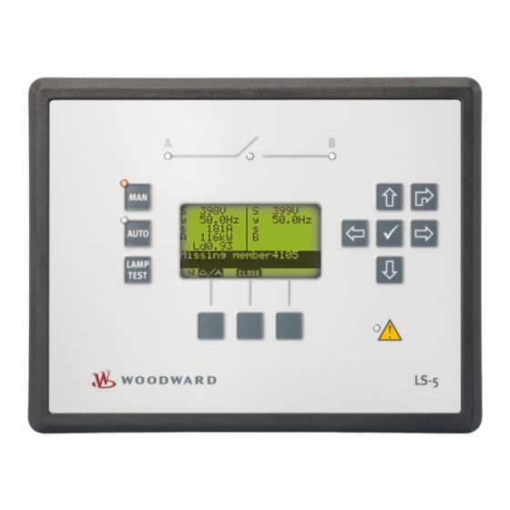
Sign In
Upload
Manuals
Brands
Woodward Manuals
Controller
LS-5 v2 Series
Woodward LS-5 v2 Series Controller Manuals
Manuals and User Guides for Woodward LS-5 v2 Series Controller. We have
1
Woodward LS-5 v2 Series Controller manual available for free PDF download: Technical Manual
Woodward LS-5 v2 Series Technical Manual (448 pages)
Circuit Breaker Control
Brand:
Woodward
| Category:
Controller
| Size: 25.51 MB
Table of Contents
Table of Contents
6
General Information
14
About this Manual
14
Revision History
14
Depiction of Notes and Instructions
15
Copyright and Disclaimer
16
Service and Warranty
17
Safety
17
Intended Use
17
Personnel
18
General Safety Notes
19
Protective Equipment and Tools
22
System Overview
23
Display and Status Indicators
24
Hardware Interfaces (Terminals)
28
Application Modes
28
Operation Modes
29
Synch. Check Functionality
29
Installation
32
Mount Unit (Sheet Metal Housing)
32
Mount Unit (Plastic Housing)
33
Clamp Fastener Installation
35
Screw Kit Installation
37
Setup Connections
38
Terminal Allocation
38
Wiring Diagram
39
Power Supply
42
Voltage Measuring
43
Breaker Interaction
43
System a Voltage
44
System B Voltage
52
Current Measuring
58
Current Measuring (System A)
58
Current Measuring (System B)
60
Power Measuring
62
Power Factor Definition
63
Analog Input 0/4 to 20 Ma
64
Discrete Inputs
66
Relay Outputs
67
Serial Interface
68
Interface
68
Service Port
69
CAN Bus Interface
71
Connecting 24 V Relays
73
Configuration
75
Basic Setup
75
Configure Language/Clock
75
Configure Display
80
Enter Password
80
System Management
82
Password System
85
Configure Status/Monitoring (Home) Screen
85
Configure Measurement
86
Configure Transformer
91
Configure Monitoring
94
System a
94
System a Operating Voltage / Frequency
95
System a Decoupling
97
Phase Shift
100
Df/Dt (ROCOF)
102
System a Overfrequency (Levels 1 & 2) ANSI# 81O
103
System a Underfrequency (Level 1 & 2) ANSI# 81U
105
System a Overvoltage (Level 1 & 2) ANSI# 59
106
System a Undervoltage (Level 1 & 2) ANSI# 27
108
System a Voltage Asymmetry
110
4.3.1.10 System a Voltage Increase
112
4.3.1.11 Setup System a for VDE-AR-N 4105
113
4.3.1.12 QV Monitoring
119
4.3.1.13 System a Time-Dependent Voltage
122
System a Phase Rotation
126
System B
127
System B Operating Voltage / Frequency
128
System B Voltage Phase Rotation
129
Breaker
131
Cba
131
Synchronization CBA
132
CBA Unload Mismatch
133
Cbb
134
Synchronization CBB
135
CBB Unload Mismatch
136
System a / System B Phase Rotation
137
CB Closed Transition Monitoring
139
Voltage Plausibility
140
Operating Range
141
CAN Interface
143
Battery Overvoltage (Level 1 & 2)
144
Battery Undervoltage (Level 1 & 2)
146
Free Configurable Alarms
147
Multi-Unit Missing Members
149
Global Settings
150
4.3.11.1 Alarm Acknowledgement
150
Configure Application
151
Application Mode
151
Breakers
153
Dead Bus Closure CB
153
Dead Bus Closure CBA/CBB
154
Configure CBA
157
Configure CBB
162
Synchronization Configuration
167
Configure Synchronous Network
171
Configure Breaker Transition Mode
172
Configure Segment
178
Automatic Run
180
Inputs and Outputs
181
Analog Input 1
181
Value Format - Examples
185
Discrete Inputs
187
Discrete Outputs (Logicsmanager)
190
Configure Interfaces
192
General
192
CAN Interface
192
CAN Interface 1
193
Additional Server Sdos (Service Data Objects)
196
Receive PDO {X} (Process Data Object)
197
Transmit PDO {X} (Process Data Object)
198
RS-232 Interface
202
Interface
203
Modbus Protocol (5300 Multiple)
204
Configure Logicsmanager
205
Configure Counters
211
Operation
214
Access Via PC (Toolkit)
214
Install Toolkit
214
Install Toolkit Configuration Files
216
Configure Toolkit
217
Connect Toolkit
219
View and Set Values in Toolkit
221
Special Screens
223
Front Panel Access
228
Basic Navigation
228
Parameter Setting Screens
236
Navigation Screens
236
Value Setting Screens
237
Logicsmanager Setting Screens
238
Main Menu Screens
239
Main Screen Display
239
Alarm List
241
System a
242
System B
242
System Angles
243
Synchroscope
243
Logicsmanager Conditions
244
Event History
245
States Easygen
245
States
246
Segments
246
5.2.3.12 Discrete Inputs/Outputs
247
5.2.3.13 Analog Input
247
5.2.3.14 System a Decoupling Thresholds
248
Test System a Decoupling (VDE-AR-N 4105)
250
5.2.3.16 Counters
250
5.2.3.17 Actual Date and Time
251
5.2.3.18 Version
251
Change Operating Modes
252
Operating Mode MANUAL
253
Operating Mode AUTOMATIC
254
Restore Language Setting
254
Application
256
Application Modes Overview
256
LS-5X2: Stand-Alone Application Mode
256
LS-5X2 & Easygen-3400/3500 or Easygen-3400XT/3500XT: Common Application Modes
257
LS-5X2 View
257
Easygen-3400/3500 or Easygen-3400XT/3500XT View
258
Setup Stand-Alone Applications (Mode A01)
259
Setup Easygen & Slave LS-5X2 Applications (Mode A05)
262
Introduction
262
Setup Easygen & Independent LS-5X2 Applications (Mode A02)
264
Introduction
264
General Functions
267
General Preparation
267
Setup Mains Measurement with Easygen
268
Setup Mains Decoupling with Easygen
269
Setup Mains Decoupling with
269
Setup Run-Up Synchronization in LS-5 Mode
272
Setup AMF Start in LS-5 Mode
272
Setup Manual Breaker Control in LS-5 Mode
275
Setup LS-5 Command Bits from Easygen to LS-5
275
Setup LS-5 Flags from LS-5 to LS-5 and Easygen
276
H-Configuration with Two Easygen and Two Incoming Mains and Tie-Breaker
278
Setup VDE-AR-N 4105 Applications
290
Introduction
290
Decoupling Device
290
Multiple Easygen-3500XT (Mode GCB/L-GGBMCB) with LS-522 as Separate Mains Decoupling Device
291
Breaker Feedback Security Procedure
292
Introduction
292
Function
293
Interfaces and Protocols
296
Interfaces
296
Interfaces Overview
296
CAN Interfaces
297
CAN Interface 1 (Guidance Level)
297
Serial Interfaces
297
Service Port (RS-232/USB)
297
RS-485 Interface
298
Protocols
298
Protocols Overview
298
Canopen Protocol
299
Modbus Protocol
300
Technical Specifications
305
Technical Data
305
Measuring Values
305
Ambient Variables
306
Inputs/Outputs
306
Interface
307
Battery
308
Housing
308
Approvals
309
Generic Note
309
Environmental Data
309
Accuracy
310
Appendix
313
Characteristics
313
Triggering Characteristics
313
Data Protocols
315
Canopen
315
Data Protocol 5301 (Basic Visualization)
315
Data Protocol 5302 (Basic Visualization)
333
Protocol 6003 (LS-5 Communication)
350
Modbus
355
Data Protocol 5300 (Basic Visualization)
355
Additional Data Identifier
399
Transmit Data
399
Logicsmanager Reference
399
Logicsmanager Overview
399
Logical Symbols
402
Logical Outputs
403
Logical Command Variables
407
Group 00: Flags Condition 1
407
Group 01: Alarm System
409
Group 02: Systems Condition
409
Group 04: Applications Condition
411
Group 05: Device Related Alarms
413
Group 06: System B Related Alarms
413
Group 07: System a Related Alarms
413
Group 08: System Related Alarms
414
Group 09: Discrete Inputs
415
Group 10: Analog Inputs
415
9.3.4.11 Group 11: Clock and Timer
416
9.3.4.12 Group 13: Discrete Outputs
416
Group 17: Alarm System 2
416
Group 24: Flags Condition
417
Group 26(/1-2): Commands Device 33 to 48
418
Group 27(/1-2): Commands Device 49 to 64
420
9.3.4.17 Group 28: LS-5 System Conditions
423
Group 29(/1-3): Commands Device 1 to 16
423
Group 30(/1-3): Commands Device 17 to 32
426
Factory Settings
428
Event and Alarm Reference
432
Alarm Classes
432
Status Messages
433
Event History
435
Event Messages
435
Alarm Messages
436
Additional Application Information
441
Synchronization of System a and System B
441
Glossary and List of Abbreviations
443
Index
445
Advertisement
Advertisement
Related Products
Woodward L-Series
Woodward LS 4
Woodward LS-522
Woodward LS-512
Woodward LS-5 Series
Woodward LS-521
Woodward easYgen LS-6XT
Woodward easYgen LS-612XT-P1
Woodward Large Electric Sonic Valve II
Woodward LESV II
Woodward Categories
Controller
Control Unit
Relays
Control Systems
Industrial Equipment
More Woodward Manuals
Login
Sign In
OR
Sign in with Facebook
Sign in with Google
Upload manual
Upload from disk
Upload from URL