Download Print this page

Advertisement

Quick Links

SERVICE MANUAL
Ver. 1.0 2017.01
Name (Model name)
Focal length (mm)
35mm equivalent
focal length*¹ (mm)
Lens groups-elements
Angle of view*²
Minimum focus*³ (m (feet))
Maximum magnification (×)
Minimum aperture
Filter diameter (mm)
Dimensions
(maximum diameter × height)
(approx., mm (in.))
Mass (approx., g (oz))
(excluding tripod collar)
Shake compensation function
For further information on compatibility with the tele
converter (sold separately) and specifications used
with the tele converter, visit the web site of Sony
in your area, or consult your dealer of Sony or local
authorized service facility of Sony.
9-896-802-11
Sony Corporation
2017A33-1
©
2017.01
Published by Sony Techno Create Corporation
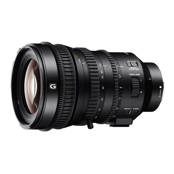
SELP18110G
(E 4/PZ 18-110 G OSS) (E PZ 18-110mm F4 G OSS)
SPECIFICATIONS
*¹ This is the equivalent focal length in 35mm format
E PZ 18-110mm
when mounted on an Interchangeable Lens Digital
F4 G OSS
Camera equipped with an APS-C sized image sensor.
SELP18110G
*² Angle of view is the value for Interchangeable Lens
18-110
Digital Cameras equipped with an APS-C sized image
27-165
sensor.
*³ Minimum focus is the distance from the image sensor
15-18
to the subject.
76°-14° 30'
0.4-0.95
Depending on the lens mechanism, the focal length
(1.31- 3.12)
may change with any change in shooting distance. The
0.122
focal lengths given above assume the lens is focused
at infinity.
f/22
95
Included items
110 × 167.5
(The number in parentheses indicates the number of
(4 3/8 × 6 5/8)
pieces.)
Lens (1), Rear lens cap (1), Lens hood (1),
1,105 (39)
Lens case (1), Zoom pin (1), Lens cap (1),
Set of printed documentation
Yes
Design and specifications are subject to change
without notice.
and
INTERCHANGEABLE LENS
Canadian Model
Chinese Model
are trademarks of Sony Corporation.
US Model
AEP Model
E-mount

Advertisement

loading

Summary of Contents for Sony Alpha E 4/PZ 18-110 G OSS

  • Page 1 (sold separately) and specifications used are trademarks of Sony Corporation. with the tele converter, visit the web site of Sony in your area, or consult your dealer of Sony or local authorized service facility of Sony. INTERCHANGEABLE LENS 9-896-802-11...
  • Page 2 DE FONCTIONNEMENT. NE REMPLACER CES COMPO- • Be sure to control soldering iron tips used for unleaded solder SANTS QUE PAR DES PIÈCES SONY DONT LES NUMÉ- and those for leaded solder so they are managed separately. ROS SONT DONNÉS DANS CE MANUEL OU DANS LES Mixing unleaded solder and leaded solder will cause detach- SUPPLÉMENTS PUBLIÉS PAR SONY.
  • Page 3 SELP18110G 1-5. NOTE ON REPLACEMENT OF OP- TICAL BLOCK FOR SERVICE To replace the Optical Block For Service, connect the E-mount lens to the ILCE-5000, and release the specified Flag in the following procedure. • Implement [Service Flag OFF (S)] of E-Mount Lens Adjust- ment (Adjustment Application for Service).
  • Page 4 SELP18110G 2. DISASSEMBLY & ASSEMBLY OPERATION NOTES Make sure that the conductive side of a flexible board does not have any stain or foreign materials. Do not touch the conductive side of flexible boards with bare hands. Plug in a flexible board straight, fully into the connector until it reaches the end inside. (Fig. 1, Fig. 2, Fig. 3) (The flexible board was plugged in straight (The flexible board was plugged in (The flexible board was not plugged in...
  • Page 5 SELP18110G 2-1. CONSTITUTION DIAGRAM small washer Red arrow direction : Shown the front (lens) side FZ washer focus ring rubber Black arrow direction : Shown the rear (mount) side ring slider sheet (F_R) small washer FZ holder zoom lever FZ washer ring slider sheet (F_R) Z-IR ring focus ring (B) block assy...
  • Page 6 SELP18110G 2-2. DISASSEMBLY • This set can be disassembled in the order shown below. 2-2-1. DISASSEMBLY FLOW Note: Remove tripod base assy before operation. FRONT SIDE (LENS SIDE) 2-2-2. FRONT ORNAMENTAL RING, 1ST DRIP PROOF RUBBER (Page 2-5) 2-2-3. ROD SUPPORT BASE, FILTER SCREW TUBE BLOCK ASSY REAR SIDE (MOUNT SIDE) (Page 2-5)
  • Page 7 SELP18110G from page 2-3 2-2-25. Z-IR RING (Page 2-16) 2-2-26. POTENTIOMETER (SLIDE TYPE) (Page 2-17) 2-2-27. REVERSE GEAR BLOCK (Page 2-17) 2-2-28. 2 GROUP BLOCK ASSY (Page 2-18) 2-2-29. 3 GROUP BLOCK ASSY (Page 2-19) 2-2-30. CAM TUBE BLOCK ASSY (Page 2-20) 2-2-31.
  • Page 8 SELP18110G Note: Follow the disassembly procedure in the numerical order given. 2-2-2. FRONT ORNAMENTAL RING, 1ST DRIP PROOF RUBBER 1 Rotate the front ornamental ring in the 2 1st drip proof rubber direction of the arrow, and remove it. Note: Remove the front ornamental ring using the name ring wrench (95 mm).
  • Page 9 SELP18110G 2-2-4. 1 GROUP BLOCK ASSY 1 three tapping screws (B2 (CH)) 2 1 group block assy 3 three adjustment washers (for partial blur adjustment (Tele side)) Note: Take note of the amount of adjustment washers. front (lens) side rear (mount) side 2-2-5.
  • Page 10 SELP18110G 2-2-6. FOCUS RING BLOCK 2 three tapping screws (B2 (CH)) 3 focus ring block 1 front FPC assy front (lens) side rear (mount) side 2-2-7. FOCUS RING RUBBER 1 focus ring rubber rear (mount) side front (lens) side...
  • Page 11 SELP18110G 2-2-8. FZ HOLDER 1 three tapping screws (B2 (CH)) 2 three FZ washers 3 FZ holder block ring slider sheet (F_R) FZ holder 4 three small washers rear (mount) side front (lens) side rear (mount) side front (lens) side ring slider sheet (F_R) 2-2-9.
  • Page 12 SELP18110G 2-2-10. F RING HOLDER (B) BLOCK ASSY 6 three tapping screws (B2 (CH)) 7 F ring holder (B) block assy 3 Remove the flexible board from the ditch. 1 ttapping screw (P1.4) 4 three hooks 2 three bosses rear (mount) side front (lens) side 5 MR encoder flexible board 2-2-11.
  • Page 13 SELP18110G 2-2-12. ZOOM RING RUBBER 2 zoom ring rubber front (lens) side rear (mount) side 1 zoom lever 2-2-13. ZOOM RING BLOCK ASSY 2 Rotate the zoom ring block assy, and align the marking. marking of the zoom ring block assy 3 zoom ring block assy marking of the main barrel 1 zoom joint pin...
  • Page 14 SELP18110G 2-2-14. REAR OUTER COVER BLOCK ASSY 1 three screws (M2) 2 rear outer cover block assy 3 tube drop protection sheet rear (mount) side front (lens) side 2-2-15. MOUNT ASSY 1 four screws 3 BL contact assy flexible board 4 mount assy 2 Lift up the mount assy in tube...
  • Page 15 SELP18110G 2-2-16. CL-1046 BOARD BLOCK 6 CL-1046 board block rear (mount) side three rubber bush A front (lens) side 1 main flexible assy 4 LF-2115 flexible board 5 boss (total five places) 3 front FPC assy CL-1046 baoard two rubber bush A 2 LF-2176 flexible board rear (mount) side front (lens) side...
  • Page 16 SELP18110G 2-2-18. MECHANICAL FUSE 3 eight screws (M2) front FPC assy 1 boss 1 boss 4 mechanical fuse 2 5 group tape mechanical fuse LF-2176 flexible board 2 5 group tape 2 5 group tape rear (mount) side front (lens) side 2-2-19.
  • Page 17 SELP18110G 2-2-20. REAR OUTER BLOCK 1 three screws (M2) 2 rear outer block rear (mount) side front (lens) side 2-2-21. TRIPOD PLATE rear (mount) side front (lens) side 2 tripod plate 1 four screws (M2) 2-14...
  • Page 18 SELP18110G 2-2-22. IRIS RING BLOCK Note 1: The steel ball comes off at the same time when you remove the iris ring block. When installing the steel ball, you must disassemble the rear outer tube block assy. 3 iris ring block Note 2: Lift the slider straight up so that you do not damage it.
  • Page 19 SELP18110G 2-2-24. REAR OUTER TUBE BLOCK, REAR OUTER TUBE INNER BLOCK 1 four tapping screws (B2 (CH)) ring slider sheet (I_R) lever retainer 2 rear outer tube block rear outer tube inner block iris (A) lock retainer front (lens) side rear (mount) side rear (mount) side lever click plate...
  • Page 20 SELP18110G 2-2-26. POTENTIOMETER (SLIDE TYPE) front FPC assy 2 two bosses rear (mount) side 1 three solders potentiometer front (lens) side (slide type) 4 potentiometer (slide type) 3 two tapping screws (P1.4) 2-2-27. REVERSE GEAR BLOCK guide shaft F_B (1.6_12.30) reverse gear 3 reverse gear block rear (mount) side...
  • Page 21 SELP18110G 2-2-28. 2 GROUP BLOCK ASSY 2 two bosses 1 tapping screw (P1.4) front FPC assy 3 boss 4 boss 6 Lift up the front FPC assy. front (lens) side 5 two hooks rear (mount) side 9 2 group block assy guide shaft J_L (2.50_66.00) guide shaft J_H...
  • Page 22 SELP18110G 2-2-29. 3 GROUP BLOCK ASSY spring of 3 group block assy 3 cam follower 2 3 group cam pin 1 hook 9 3 group block assy 4 SN sheet guide shaft J_H (2.50_87.50) guide shaft J_L 7 3 group flexible board (2.50_66.00) 6 two bosses 5 tapping screw...
  • Page 23 SELP18110G 2-2-30. CAM TUBE BLOCK ASSY 2 guide shaft J_L (2.50_66.00) 1 two guide shafts 4 cam tube block assy J_H (2.50_87.50) screw hole 3 Rotate the cam tube block assy in the direction of the arrow and aligning the screw hole with the groove. ditch front (lens) side screw hole...
  • Page 24 SELP18110G 2-2-32. MAIN FLEXIBLE BLOCK 4 tapping screw 5 boss (UB1.2 (CH)) 1 5 group tape qh MR spacer Note 1: Take note of the amount of MR spacer. 3 5 group tape 2 mirror tube flexible board qf tapping screw (UB1.2 (CH)) rear (mount) side qg main flexible block...
  • Page 25 SELP18110G 2-2-33. MIRROR TUBE COMPLETE ASSY 2 four screws 5 mirror tube complete assy 4 Draw the zoom motor wire out of the hole in mirror tube complete assy. 3 Lift up the mirror tube complete assy. 1 F linear magnet assy rear (mount) side front (lens) side 2-2-34.
  • Page 26 SELP18110G 2-2-35. 4 GROUP BLOCK ASSY, F INNER YOKE ASSY 4 group flexible board 2 two bosses 1 tapping screw (UB1.2 (CH)) main barrel (from rear (mount) side) 4 4 group block assy guide shaft J_L (2.50_66.00) guide shaft (FM) F inner yoke assy rear (mount) side front (lens) side...
  • Page 27 SELP18110G 2-2-36. ZOOM MOTOR ASSY 3 type-E stop ring 2.0 5 zoom motor block zoom motor assy 2 boss two bushings A 1 tapping screw rear (mount) side (B2 (CH)) front (lens) side cylinder 4 motor shaft assy 2-2-37. MAIN BARREL 2 two bosses 1 tapping screw (UB1.2 (CH))
  • Page 28 SELP18110G 2-3. ASSEMBLY • This set can be assembled in the order shown below. 2-3-1. ASSEMBLY FLOW MAIN BARREL REAR OUTER TUBE INNER BLOCK IRIS RING BLOCK ASSY 2-3-2. MAIN BARREL MASK 2-3-16. LEVER CLICK PLATE, 2-3-17. RING SLIDER SHEET (I_F) (Page 2-27) RING SLIDER SHEET (I_R) (Page 2-37)
  • Page 29 SELP18110G F RING HOLDER (A) BLOCK 2-3-34. MR ENCODER (Page 2-46) 2-3-35. FOCUS RING (A) BLOCK ASSY (Page 2-47) 2-3-36. F RING HOLDER (B) BLOCK ASSY (Page 2-47) 2-3-37. FOCUS RING (B) BLOCK ASSY from page 2-25 (Page 2-48) 2-3-32. ZOOM RING BLOCK ASSY 2-3-38.
  • Page 30 SELP18110G Note: Follow the assembly procedure in the numerical order given. 2-3-2. MAIN BARREL MASK 3 two bosses 4 tapping screw (UB1.2 (CH)) 1 main barrel main barrel 2 main barrel mask (from rear (mount) side) rear (mount) side front (lens) side 2-3-3.
  • Page 31 SELP18110G 2-3-4. 4 GROUP BLOCK ASSY 3 F inner yoke assy 1 guide shaft J_L (2.50_66.00) 2 guide shaft (FM) main barrel (from rear (mount) side) hole for guide shaft (FM) rear (mount) side hole for guide shaft ditch for F inner yoke assy J_L (2.50_66.00) front (lens) side 4 4 group block assy...
  • Page 32 SELP18110G 2-3-5. SWITCH SLIDER (MS) 2 FM shaft 4 hook 3 switch slider spring 5 hook rear (mount) side 1 switch slider (MS) front (lens) side 2-3-6. MIRROR TUBE COMPLETE ASSY 4 four screws 1 mirror tube complete assy 2 Pass the zoom motor wire through the hole of the mirror tube complete assy.
  • Page 33 SELP18110G 2-3-7. MAIN FLEXIBLE ASSY main flexible assy 1 Crease the main flexible assy. : Mountain fold : Valley fold 2 MR sensor (RM) 3 four solders Note 1: Apply the adhesive bond to soldering position. B-110 qj tapping screw qh boss (UB1.2 (CH)) 4 two bosses...
  • Page 34 SELP18110G 2-3-8. FRONT FPC ASSY 1 front FPC assy 2 tapping screw rear (mount) side (UB1.2 (CH)) front (lens) side 2-3-9. CAM TUBE BLOCK ASSY 2 Align the screw hole of cam tube block assy with the ditch of main barrel and install the cam tube block assy.
  • Page 35 SELP18110G 2-3-10. GUIDE SHAFT 2 two guide shafts J_H (2.50_87.50) 1 guide shaft J_L (2.50_66.00) hole for guide shaft main barrel J_H (2.50_87.50) (from front (lens) side) hole for guide shaft J_L (2.50_66.00) front (lens) side rear (mount) side 2-32...
  • Page 36 SELP18110G 2-3-11. 3 GROUP BLOCK ASSY 1 3 group block assy 4 Pass the 3 group flexible board through the hole of the main barrel. 2 Catch the 3 group flexible board on the claw. 3 Install the 3 group block assy.
  • Page 37 SELP18110G 2-3-12. 2 GROUP BLOCK ASSY 1 2 group block assy guide shaft J_L (2.50_66.00) guide shaft J_H (2.50_87.50) front (lens) side cam follower rear (mount) side 3 3 group cam pin cam follower 2 cam follower Note 1: When replacing the cam follower, choose parts that do not cause backlash and confirm that movement is smooth.
  • Page 38 SELP18110G 2-3-13. REVERSE GEAR 2 guide shaft F_B (1.6_12.30) long (rear (mount) side) short 1 reverse gear (front (lens) side) Note: Apply grease to all surfaces. SG-310 3 reverse gear block rear (mount) side 5 two screws (BTITE (1.4 (CH)) 4 reverse gear holder front (lens) side 2-3-14.
  • Page 39 SELP18110G 2-3-15. Z-IR RING 5 three tapping screws (B2 (CH)) protection belt (I_F) 4 Install by aligning the convex part of the Z-IR ring block with the front FPC assy. 1 Z-IR ring convex part rear (mount) side front (lens) side front FPC assy rear (mount) side 3 ring slider sheet (Z_R)
  • Page 40 SELP18110G 2-3-17. RING SLIDER SHEET (I_F) 2 ring slider sheet (I_F) 3 Apply grease to six places. SG-310 front (lens) side rear (mount) side 1 iris ring block assy iris ring block assy (from front (lens) side) 2-3-18. IRIS RING BLOCK 2 Install by aligning the groove of the iris ring block with the slider.
  • Page 41 SELP18110G 2-3-19. CLICK LEVER RETAINER rear (mount) side click holder click holder front (lens) side 2 ring click spring ditch 3 Align the convex part of click lever retainer and ditch. 1 ball steel convex part boss 4 Move the click lever retainer in the direction of the arrow. lever click plate lever click plate click lever retainer...
  • Page 42 SELP18110G 2-3-21. REAR OUTER TUBE BLOCK 2 four tapping screws (B2 (CH)) 1 Align the hole of OPTICAL STEADY SHOT with the lever retainer, and install the rear outer tube block. Note 1: Take care so that the flexible board is not pinched.
  • Page 43 SELP18110G 2-3-23. TRIPOD PLATE rear (mount) side front (lens) side 1 tripod plate 2 four screws (M2) Note: Apply the adhesive bond to the tip of screws. B-40 2-3-24. REAR OUTER BLOCK 2 three screws (M2) Note 2: Apply the adhesive bond to the tip of screws. B-40 1 Align the index and install the rear outer block.
  • Page 44 SELP18110G 2-3-25. G17 BLOCK ASSY 4 three tapping screws (1.7) (CH) 3 Align the marking and install marking of the G17 block assy the G17 block assy. 2 three adjustment washers (for partial blur adjustment (Wide side)) Note: Install exactly as recorded during disassembly. marking of the mirror tube complete assy 1 three G18 springs rear (mount) side...
  • Page 45 SELP18110G 2-3-27. CL-1050 BOARD 1 CL-1050 board 2 LF-2115 flexible board Note: Take care note of the orientation . short convex part 3 CL-1050 board block long 4 connector 5 Arrange the wire under the rib. 6 Arrange the rest of the wire. rear (mount) side front (lens) side hole...
  • Page 46 SELP18110G 2-3-28. CL-1046 BOARD 2 three rubber bush A 1 CL-1046 baoard rear (mount) side long (rear (mount) side) short (front (lens) side) front (lens) side rubber bush A 2 two rubber bush A 3 Align rubber bush A (total five pieces) and bosses (total five places), and install the CL-1046 board block.
  • Page 47 SELP18110G 2-3-30. MOUNT ASSY 3 four screws 1 BL contact assy flexible board 2 mount assy rear (mount) side front (lens) side 2-3-31. REAR OUTER COVER BLOCK ASSY 3 three screws (M2) Note 2: Apply the adhesive bond to the tip of screws. B-40 2 Align the index with the center of zoom lever and install the rear outer cover block assy.
  • Page 48 SELP18110G 2-3-32. ZOOM RING BLOCK ASSY 2 Align the marking and install the zoom ring block assy. marking of the zoom ring block assy marking of the main barrel front (lens) side rear (mount) side 1 Rotate the cam tube block assy fully in the direction of the arrow.
  • Page 49 SELP18110G 2-3-33. ZOOM RING RUBBER 1 Align the two holes with the two projections of the zoom ring block assy and install the zoom ring rubber. zoom ring rubber two holes Note: Face the surface with the grooves toward the rear (mount) side when installing.
  • Page 50 SELP18110G 2-3-35. FOCUS RING (A) BLOCK ASSY focus ring (A) block assy (from rear (mount) side) 4 focus ring (A) block assy 3 Apply grease to six places. G-85 rear (mount) side front (lens) side 2 Apply grease to ten places. 1 Apply grease.
  • Page 51 SELP18110G 2-3-37. FOCUS RING (B) BLOCK ASSY 2 Install by aligning the groove of the focus ring (B) block assy with the slider. Note: Take care so that the flexible board is not pinched. groove flexible board groove center rear (mount) side front (lens) side 1 Match the slider with the position shown in the figure.
  • Page 52 SELP18110G 2-3-38. FZ HOLDER 5 ring slider sheet (F_R) 6 Apply grease to four places. SG-310 2 Apply grease to four places. G-85 FZ holder (from rear (mount) side) FZ holder 1 FZ holder (from front (lens) side) rear (mount) side 4 Apply grease to eight places.
  • Page 53 SELP18110G 2-3-39. FOCUS RING RUBBER 1 focus ring rubber focus ring rubber Note: Face the surface with the grooves toward the front (lens) side when installing. rear (mount) side front (lens) side 2-3-40. FOCUS RING BLOCK 2 three tapping screws (B2 (CH)) 1 Align the marking, and install the focus ring block.
  • Page 54 SELP18110G 2-3-41. FRONT FRAME BLOCK 6 three tapping screws (B2 (CH)) 4 three tapping screws (1.7) (CH) 5 Align the marking, and install 3 cam tube thrust spring the front frame block. marking 2 three adjustment washers rear (mount) side marking front (lens) side 1 fixed holding (front) tube block...
  • Page 55 SELP18110G 2-3-43. FILTER SCREW TUBE BLOCK ASSY, ROD SUPPORT BASE 2 three tapping screws (1.7) (CH) 1 Align the two holes with the two bosses, and install the filter screw tube block assy. hole 3 rod support base boss hole 4 two hexagon socket bolts (2 boss front (lens) side...
  • Page 56 SELP18110G 3. EXPLODED VIEWS Note: • -XX and -X mean standardized parts, so they may have some difference from the original one. • Items marked “*” are not stocked since they are seldom required for routine service. Some delay should be anticipated when ordering these items.
  • Page 57 SELP18110G 3-2. FOCUS RING SECTION Red arrow direction : Shown the front (lens) side Black arrow direction : Shown the rear (mount) side not supplied not supplied Ref. No. Part No. Description Ref. No. Part No. Description A-2179-960-A HOLDER (A) BLOCK ASSY, F RING 4-298-700-01 SCREW, TAPPING B2 (CH) 1-493-101-12...
  • Page 58 SELP18110G 3-3. MOUNT SECTION Red arrow direction : Shown the front (lens) side Black arrow direction : Shown the rear (mount) side Refer to main barrel section. Refer to rear outer section. 108 109 not supplied not supplied Ref. No. Part No.
  • Page 59 SELP18110G 3-4. REAR OUTER SECTION Red arrow direction : Shown the front (lens) side Black arrow direction : Shown the rear (mount) side not supplied not supplied not supplied not supplied not supplied not supplied not supplied 158 159 not supplied not supplied Ref.
  • Page 60 SELP18110G 3-5. MAIN BARREL SECTION Red arrow direction : Shown the front (lens) side Black arrow direction : Shown the rear (mount) side (Note 4) (Note 4) (Note 4) not supplied (Note 3) not supplied not supplied (Note 2) SERVICE, 4 GROUP BLOCK ASSY not supplied (Note 1) not supplied...
  • Page 61 SELP18110G 3-6. REPAIR PARTS FOR SERVICE Red arrow direction : Shown the front (lens) side Black arrow direction : Shown the rear (mount) side (Note 1) not supplied not supplied not supplied not supplied (Note 2) not supplied (Note 2) not supplied not supplied not supplied...
  • Page 62 SELP18110G 3-7. SELECTION PARTS Ref. No. 9, 229 ADJUSTMENT WASHER Ref. No. 225 MR SPACER (1190) (for resolving power (partial blur) adjustment) Select the same size part as before disassembly. This part is for resolving power (partial blur) adjustment. Adjust the thickness by following the results of the resolving power check.
  • Page 63 SELP18110G 4. SUPPLIED ACCESSORIES Note: • Items marked “*” are not stocked since they are seldom required for routine service. Some delay should be anticipated when ordering these items. Ref. No. Part No. Description 4-590-042-03 MANUAL, INSTRUCTION (JAPANESE, ENGLISH, FRENCH, SPANISH, SIMPLIFIED CHINESE) 4-590-042-13 MANUAL, INSTRUCTION (GERMAN, DUTCH, SWEDISH, ITALIAN, PORTUGUESE)
  • Page 64 SELP18110G 5. ADJUSTMENTS Note: When disassembled the lens, after the assembly has been completed, perform adjustments by referring to this chapter. 5-1. BEFORE STARTING ADJUSTMENTS 5-1-1. Adjustment Items after Replacing Parts When replacing main parts and boards, adjust or check the items indicated by z in the following table. Note: Do not adjust the items indicated by .
  • Page 65 SELP18110G 5-1-2. Adjustment/Check Procedure Flow Chart After the parts replacement Replace the 2-3 Group 1st Time Block Assy Replace the 4 Group 2nd Time Block Assy It does not improve 5-2-2. Optical axis the symptoms. check 5-4. Resolving power adjustment Perform the Resolving power adjustment, it does not...
  • Page 66 SELP18110G 5-1-3. List of Service Tools and Equipment Service Tools/Equipments Part No. Remarks E-Mount_Lens_Adjustment_(E).zip Lens adjustment program ― (Adjustment Application for Service) E-Mount Lens Adjustment Version: 1.4.1.5 or higher Lens adjustment program BLG-TestProgramV[][][].exe ― BLG-Test Program Version: 1.0.0.1 or higher B-L Control Box J-6082-774-A Supplied with D-sub 15-pin cable...
  • Page 67: Table Of Contents

    SELP18110G Service Tools/Equipments Part No. Remarks Refer to Fig. 4 AC adaptor (AC-PW20) 1-487-963-12/22 1-487-963-12: Except US, Canadian 1-487-963-22: US, Canadian Flange back adjustment jig J-6082-563-A Refer to Fig. 5 Refer to Fig. 6 FB adjustment chart (5 mm) J-6082-818-A For “Flange Back Adjustment”.
  • Page 68: 1000 Mm Collimator

    SELP18110G 5-2. OPTICAL AXIS CHECK Setting of the Flange Back Tester 1. Set the equipment as shown in the following figure. 5-2-1. Setting/Preparation of the Flange Back (f’F) Dial Gauge A-mount attachment (Min. scale: 0.01 mm) Measuring Instrument Objective lens (10x) Eyepiece lens (7x) Equipment (Common) •...
  • Page 69 SELP18110G Preparations of Using a Camera (General E-mount Preparations of Using a B-L Control Box Interchangeable Lens Digital Camera) Equipment • Personal Computer (See Note 1) Equipment • B-L Control Box (Supplied with D-sub 15-pin cable) • Camera (General E-mount interchangeable lens digital camera) •...
  • Page 70 SELP18110G 5. When starting and finishing the BLG-TestProgram, perform the following procedure. • Starting the BLG-TestProgram • Finishing the BLG-TestProgram Procedure of Starting Procedure of Finishing (1) Mount a lens to be tested to the lens mount block. (1) Click [Power] to turn off the power to the lens. (2) Connect the D-sub 15-pin cable to the lens mount block, and (2) Confirm that the two LEDs on the B-L Control Box are not lit.
  • Page 71 SELP18110G 6. Start the lens adjustment program “BLG-TestProgramV[][][].exe”. 7. When [Open] is clicked and communication between personal computer and B-L Control Box is connected, the button name changes to [Close] and the [Power] button is made active. 8. Click [Power] to supply power to the lens to be tested. At this time, confirm that both of the two LEDs on the B-L Control Box are light.
  • Page 72 SELP18110G 10. Align the plane mirror with the center projected image on the screen, and confirm again that the reflected light illuminates the center of the lens to be tested. If the reflected light position is deviated, re-adjust the lens projector position. 11.
  • Page 73 SELP18110G 5-2-2. Optical Axis Check Checking Procedure 1. Adjust the optical axis while observing the microscope until the chart image can be seen in the center. 2. Perform steps (1) to (6) and check that the AS and CB values are within specifications.
  • Page 74: Resolution Check Chart (Ilc)

    SELP18110G 5-3. RESOLVING POWER CHECK 5-3-1. Photographic Resolving Power Check For this lens, it is necessary to check the photographic resolving power with two kinds of focal length (18 mm, 110 mm). Therefore, please check with the case where the zoom set to the WIDE end (focal length: 18 mm) and the case where it is set to the TELE end (focal length: 110 mm).
  • Page 75 SELP18110G 5-3-2. Setting/Preparation of the Lens Test Projector Preparations of Using a Camera (General E-mount Interchangeable Lens Digital Camera) Equipment and Tools • Camera (General E-mount interchangeable lens digital camera) • Lens Test Projector (F) • E-mount APSC jig for Lens Test Projector (F) and E-mount attachment (See Note) •...
  • Page 76 SELP18110G Preparations of Using a B-L Control Box Equipment and Tools • Personal Computer (See Note 1) • B-L Control Box (Supplied with D-sub 15-pin cable) • AC cable (Sold on the market) • RS-232C Cable (D-sub 9-pin (Male with securing screws), D-sub 9-pin (Female with securing screws)) Straight type (Sold on the market) •...
  • Page 77 SELP18110G (2) Starting and Finishing the BLG-TestProgram • Finishing the BLG-TestProgram • Starting the BLG-TestProgram Procedure of Finishing 1. Click [Power] to turn off the power to the lens. Procedure of Starting 2. Confirm that the two LEDs on the B-L Control Box are not lit. 1.
  • Page 78 SELP18110G (3) Setting Method Setting Procedure 1. Start the lens adjustment program “BLG-TestProgramV[][][].exe”. 2. When [Open] is clicked and communication between personal computer and B-L Control Box is connected, the button name changes to [Close] and the [Power] button is made active. 3.
  • Page 79 SELP18110G 5. Align the plane mirror with the center projected image on the screen, and confirm again that the reflected light illuminates the center of the lens to be tested. If the reflected light position is deviated, re-adjust the lens projector position. 6.
  • Page 80 SELP18110G 9. Clicking [Focus(Target Dist.)] displays the focus JOG operation window. Focus position indicator Select focus step value Select and enter focus step speed Focus drive Focus drive (near) (far) 10. Adjust the focus position with [Near] and [Far] while selecting “Focus Step” and “Low”/“Mid”/“High”, and then click [OK] to close the focus JOG window.
  • Page 81 SELP18110G 5-3-3. Projective Resolving Power Check Reference value: Number of projective resolving power lines (lines/mm) Focal length f Distance (m) (mm) Peripheral (y' = 10) Peripheral (y' = 12) Center (y' = 0) 0.72 More than More than More than More than More than 80 lines...
  • Page 82 SELP18110G 4. Read the value of the number of projective resolving power lines (maximum resolving power) of the center projected image (y’ = 0). 5. Read the value (the number of projective resolving power lines) of the thinnest line (resolution limit) that allows recognition of contrast of the sagittal (S) image and meridional (M) image (three lines) of the peripheral projected image (y’...
  • Page 83 SELP18110G 5-4. RESOLVING POWER ADJUSTMENT 5-4-2. Partial Blur Adjustment (Wide side) Note: Resolving Power Adjustment is done by increasing or decreas- Adjusting Procedure ing the thickness of the washer. 1. Increase or decrease the thickness of the adjustment washer to Refer to “2-2.
  • Page 84: Siemens Star Chart

    SELP18110G 5-5. PERFORMANCE CHECK 5-5-2. Take a Movie for Performance Check (Image Shaking/Jumping) (IMAGE SHAKING/JUMPING) Capture a moving image of chart with the settings of “5-5-1. Prepa- rations”. Equipment and Tools • Flange back adjustment jig Capture conditions: • Siemens star chart Capture a moving image by operating the zoom as shown •...
  • Page 85 SELP18110G 5-6. E-MOUNT LENS ADJUSTMENT (1) Installation For adjustment of the SELP18110G, prepare a version 1.4.1.5 or higher of the lens adjustment program (E-Mount Lens Adjustment. Equipment and Tools zip). • Personal Computer (See Note) • HASP key (SeusEX) Note: Perform the installation by administrator privileges. •...
  • Page 86 SELP18110G 5. The installer start up screen appears, then click the [Next] button 5-6-2. Precautions for Use to start the installation. • When the instruction “PUSH ENTER” as shown below is displayed on the screen, if the “PUSH ENTER” does not disappear even after pressing the ENTER key, press it again.
  • Page 87 SELP18110G 5-6-3. Method of Starting and Finishing 5-6-4. Adjustment Method of Each Item (1) Starting the E-Mount Lens Adjustment (1) Lens Device (S) Make sure to disconnect the AC adaptor after finishing the adjustment • Check the switch operation. (including the case when stops due to an error). •...
  • Page 88 SELP18110G 4. After the focusing ring check is completed, message screen is 7. Turn the zoom ring to the CAP side. displayed in the following order. Operate the steady shot switch Zoom ring in accordance with the message. MOV side CAP side Focal length index Align the value “18”...
  • Page 89 SELP18110G 10. When the ENTER key is pressed, message screen is displayed 12. When the ENTER key is pressed, the message screen is displayed in the following order. Operate the ZOOM switch in accordance in the following order. Operate the focusing ring accordance with with the message.
  • Page 90 SELP18110G 16. When the ENTER key is pressed, automatically starts the focus- 20. After the iris ring adjustment is completed, the message screen ing ring AD value check. is displayed in the following order. According to the instructions of the screen, check the iris ring in order of “22” to “A”, by one graduation every.
  • Page 91 SELP18110G 22. When the ENTER key is pressed, the message screen is displayed 23. After the POWER ZOOM lever adjustment is completed, mes- in the following order. Operate and adjust the POWER ZOOM sage screen is displayed in the following order. Operate and check lever accordance with the message.
  • Page 92 SELP18110G 25. When the ENTER key is pressed, message screen is displayed 28. When the ENTER key is pressed, message screen is displayed in the following. Slide the locking switch in the direction of the in the following. Set the ZOOM switch to the “SERVO”. arrow.
  • Page 93 SELP18110G 31. When the ENTER key is pressed, message screen is displayed 34. When the ENTER key is pressed, message screen is displayed in the following. Slide the locking switch in the direction of the in the following. Set the ZOOM switch to the “SERVO”. arrow.
  • Page 94 SELP18110G 37. When the ENTER key is pressed, message screen is displayed (2) Lens Device2 (S) in the following. Set the ZOOM switch to the “SERVO”. • Adjust the MR sensor of focus and zoom. • Adjust the mechanical end of focus and zoom. Subject Not required •...
  • Page 95 SELP18110G 5. Turn the zoom ring to the MOV side. 8. When the ENTER key is pressed, automatically starts the zoom MR adjustment. Zoom ring MOV side CAP side 9. After the zoom MR adjustment is completed, message screen is displayed in the following. Slide the locking switch in the Focal length index direction of the arrow.
  • Page 96 SELP18110G 11. When the ENTER key is pressed, message screen is displayed in (3) Steady Hall (S) the following order. Operate the zoom ring in accordance with • Adjust the position detection hall element for shake compensation. the message. Subject Not required Operation on Lens side Not required...
  • Page 97 SELP18110G (4) Flange Back (S) 4. When the ENTER key is pressed, message screen is displayed in the following. Set the focusing ring to the “AF/MF”. • Adjust the flange back of inner focus lens. Flange back adjustment jig Subject + FB adjustment chart •...
  • Page 98 SELP18110G (5) F Number (S) (6) ROM Check • Adjust the F number. • Check the switch operation. • Check the data stored in the EEPROM on the Main Board. Subject Not required Subject Not required Operation on Lens side Not required •...
  • Page 99 SELP18110G 4. When the ENTER key is pressed, message screen is displayed 7. “SW CHECK OK” is displayed when the check is completed. in the following. Set the focusing ring to the “FULL MF”. 8. When the ENTER key is pressed, “FINISHED” of the SW Focusing ring CHECK is displayed and click the “OK”...
  • Page 100 SELP18110G (7) Adjustment execute Check (9) Lens Sleep • Check whether the lens adjustment has been successful. • Set the lens to the sleep mode. Subject Not required Subject Not required Operation on Lens side Not required Operation on Lens side Not required Shooting Mode of the camera P mode (Program Auto) Shooting Mode of the camera P mode (Program Auto)
  • Page 101 SELP18110G Revision History Ver. Date History Contents 2017.01 Official Release —...

This manual is also suitable for:

Alpha e pz 18-110mm f4 g ossSelp18110g