Table of Contents
Advertisement
Quick Links
172-65126MA-10 (FL5/FL21/FL32/FL5-C/FL21-C/FL32-C + BD2) 10 March 2017
Instruction Manual
Instruction Manual
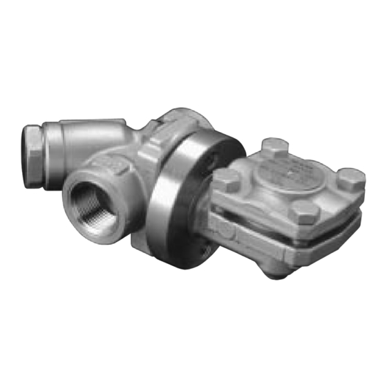
Thermostatic Steam Trap
QuickTrap
®
FL5 / FL21 / FL32
FL5-C / FL21-C / FL32-C
Trap Unit
L5 / L21 / L32
L5-C / L21-C / L32-C
(For Connector Body F46)
Copyright © 2017 by TLV CO., LTD.
All rights reserved
Advertisement
Table of Contents

Summary of Contents for TLV QuickTrap FL5
- Page 1 Thermostatic Steam Trap QuickTrap ® FL5 / FL21 / FL32 FL5-C / FL21-C / FL32-C Trap Unit L5 / L21 / L32 L5-C / L21-C / L32-C (For Connector Body F46) Copyright © 2017 by TLV CO., LTD. All rights reserved...
-
Page 2: Table Of Contents
Contents Introduction ................1 Checking the Piping ..............4 Specifications ................5 Compatibility ................6 Configuration ................6 Installation ................7 Maintenance ................8 Disassembly / Reassembly ............. 9 Instructions for Plug / Holder Disassembly and Reassembly 12 Troubleshooting ..............13 Product Warranty .............. - Page 3 • The three types of cautionary items above are very important for safety: be sure to observe all of them as they relate to installation, use, maintenance and repair. Furthermore, TLV accepts no responsibility for any accidents or damage occurring as a result of failure to observe these precautions.
- Page 4 CAUTION Be sure to use only the recommended components when repairing the product, and NEVER attempt to modify the product in any way. Failure to observe these precautions may result in damage to the product and burns or other injury due to malfunction or the discharge of fluids.
-
Page 5: Checking The Piping
3. Have isolation valves been installed at the inlet and outlet? If the outlet is subject to back pressure, has a check valve (TLV-CK) been installed? 4. Is the inlet pipe as short as possible, with as few bends as possible, and installed so the liquid will flow naturally down into the trap? 5. -
Page 6: Specifications
Specifications Install properly and DO NOT use this product outside the recommended operating pressure, temperature and other specification ranges. CAUTION Improper use may result in such hazards as damage to the product or malfunctions which may lead to serious accidents. Local regulations may restrict the use of this product to below the conditions quoted. -
Page 7: Compatibility
Compatibility • The FL QuickTrap series employs a connector unit (F46) and is not compatible with QuickTrap models using connector unit F46J. • Trap unit (L5/L5-C/L21/L21-C/L32/L32-C) is compatible with Trap Stations (V1/V2/V1P/V2P Series) and can be installed on those trap stations or connector unit (F32). -
Page 8: Installation
Installation Install properly and DO NOT use this product outside the recommended operating pressure, temperature and other specification ranges. CAUTION Improper use may result in such hazards as damage to the product or malfunctions which may lead to serious accidents. Local regulations may restrict the use of this product to below the conditions quoted. -
Page 9: Maintenance
(When conducting a visual inspection, flash steam is sometimes mistaken for steam leakage. For this reason, the use of a steam trap diagnostic instrument [such as TLV TrapMan if appropriate] in conjunction with the visual inspection is highly recommended.) -
Page 10: Disassembly/Reassembly
Disassembly/Reassembly When disassembling or removing the product, wait until the internal pressure equals atmospheric pressure and the surface of the product CAUTION has cooled to room temperature. Disassembling or removing the product when it is hot or under pressure may lead to discharge of fluids, causing burns, other injuries or damage. - Page 11 Removing/Reassembling the Components Inside the Body Part During Disassembly During Reassembly Cover Bolt Remove with a socket wrench Consult the table of tightening Figure B torques and tighten to the proper torque Trap Cover Lift straight up and out. Make sure there are no Remove without scratching pieces of the old gasket left the surface.
- Page 12 Exploded View Nameplate (T) Cover Bolt (T) Inner/Outer Connector Gaskets (T) Trap Cover (T) Spring Clip (T) Connector Body (C) Connector Bolt (T) X-element (T) Connector Valve Seat (T) Nameplate (C) X-element Guide (T) Trap Screen (T) Cover Gasket (T) Screen (C) Screen Holder Gasket (C) Screen Holder (C)
-
Page 13: Instructions For Plug/Holder Disassembly And Reassembly
Instructions for Plug/Holder Disassembly and Reassembly The seal on the threaded plugs/holders found on TLV products is formed by a flat metal gasket. There are various installation orientations for the gaskets, such as horizontal, diagonal and downward, and the gasket may be pinched in the thread recesses during assembly. -
Page 14: Troubleshooting
Troubleshooting When disassembling or removing the product, wait until the internal pressure equals atmospheric pressure and the surface of the product CAUTION has cooled to room temperature. Disassembling or removing the product when it is hot or under pressure may lead to discharge of fluids, causing burns, other injuries or damage. -
Page 15: Product Warranty
One year following product delivery. 2. Warranty Coverage TLV CO., LTD. warrants this product to the original purchaser to be free from defective materials and workmanship. Under this warranty, the product will be repaired or replaced at our option, without charge for parts or labor. -
Page 16: Options
Options With Blowdown Valve (TLV BD2) Always wear eye protection and heat-resistant gloves when operating CAUTION the blowdown valve. Failure to do so may result in burns or other injury. When operating the blowdown valve, stand to the side well clear of the outlet to avoid contact with internal fluids that will be discharged. - Page 17 BD2 Blowdown Valve Operation The BD2 valve is in the closed position when the BD2 is shipped from the factory. Before attempting to operate the BD2, reconfirm that the BD2 valve is still in the closed position. Locate the blow outlet and, during operation, stand to the side and well clear of it, as the jet of condensate or steam could cause burns.


Need help?
Do you have a question about the QuickTrap FL5 and is the answer not in the manual?
Questions and answers