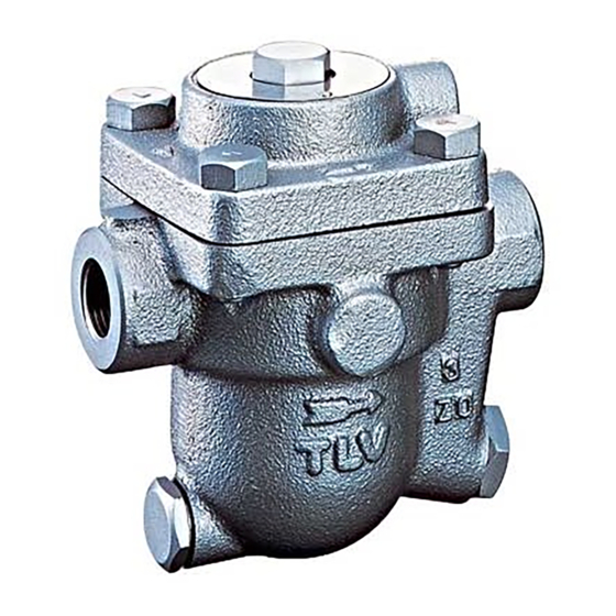
Option: Pressure-balancing Line Connection (no X-element) ..................23 Introduction Thank you for purchasing the TLV free float steam trap. This product has been thoroughly inspected before being shipped from the factory. When the product is delivered, before doing anything else, check the specifications and external appearance to make sure nothing is out of the ordinary.
The three types of cautionary items above are very important for safety: be sure to observe all of them as they relate to installation, use, maintenance and repair. Furthermore, TLV accepts no responsibility for any accidents or damage occurring as a result of failure to observe these precautions.
Page 4
Use gloves when operating the lock release valve and keep all CAUTION body parts well clear of the product. Failure to do so could result in burns, other injury or damage from the blowing of small amounts of steam and condensate. When disassembling or removing the product, wait until the internal pressure equals atmospheric pressure and the surface of the product has cooled to room temperature.
4. Have isolation valves been installed at the inlet and outlet? If the outlet is subject to back pressure, has a check valve (TLV-CK) been installed? 5. Is the inlet pipe as short as possible, with as few bends as possible, and installed so the liquid will flow naturally down into the product? 6.
Operation Principles of air and condensate discharge: 1. Initial Air and Cold Condensate Discharge At startup, before steam is supplied, the trap is cold so the X-element is contracted and the air vent valve seat (A) is open. This allows for the rapid discharge of air through the air vent valve (A) and cold condensate through the orifice (B), when steam is first supplied to the system.
Use only under conditions in which no freeze-up will occur. Freezing may damage the product, leading to fluid discharge, which may cause burns or other injury. Refer to the product nameplate for detailed specifications. J3X/JF3X J5X/JF5X/J7X/J7.2X/J7.5X/J8X Model Nominal Diameter Maximum Allowable Pressure (PMA)*...
Page 9
Element Retainer Spring Pin Lock Release Valve Option for J3X and J5X Option: LR3 for J3X and JF3X, LR5 for J4X and JF5X For J7X, J7.2X, J7.5X, and J8X For J3X, JF3X, J5X, and JF5X 172-65132MA-07 (JX Series) 16 Feb 2022...
If there is a problem, determine the cause using the “Troubleshooting” section in this manual. Tolerance Angle for Installation: 5° Make sure the product is installed with the raised TLV lettering on the body horizontal. 172-65132MA-07 (JX Series) 16 Feb 2022...
(When conducting a visual inspection, flash steam is sometimes mistaken for steam leakage. For this reason, the use of a steam trap diagnostic instrument such as TLV TrapMan in conjunction with the visual inspection is highly recommended.)
Operating the Optional Lock Release Valve Use only under conditions in which no water hammer will occur. CAUTION The impact of water hammer may damage the product, leading to fluid discharge, which may cause burns or other injury. Use on equipment where steam-locking/air binding, which slows the discharge of condensate and reduces equipment efficiency, tends to occur (cylindrical dryers, air fin heater, etc.).
Page 13
Steam Discharge (valve fully open) Air Discharge (valve fully open) Differential Pressure (psi) Differential Pressure (psi) * Capacities are equivalent capacities of standard air (air at 68°F and atmospheric pressure) 172-65132MA-07 (JX Series) 16 Feb 2022...
Element Remove while turning – – Retainer 33 * Stamped 3 or 5: 3 for J3X and JF3X, 5 for J5X and JF5X Figure A 172-65132MA-07 (JX Series) 16 Feb 2022...
Page 15
Removing/Reattaching Drain Plug J(F)3X During Part J7.2X J7.5X During Reassembly J(F)5X Disassembly Drain Plug Remove with a Coat threads with anti-seize; consult the – – * socket wrench table of tightening torques and tighten to the proper torque Drain Plug Remove the Replace with a new gasket –...
Page 16
Removing/Reassembling Components Inside the Cover J(F)3X Part J7.2X J7.5X During Disassembly During Reassembly J(F)5X Snap Ring Pinch the insides Insert securely into the snap ring together and remove groove in the cover – (X-element Cover 17) X-element Make sure the mesh side is facing ...
Page 17
J(F)3X Part J7.2X J7.5X During Disassembly During Reassembly J(F)5X Screen Lift straight up and out Insert into the body straight – – Holder Retainer 11 Screen Lift straight up and out Insert into body, making sure the – ...
Page 18
Table of Tightening Torques Parts Model J3X/JF3X J5X/JF5X J7.2X J7.5X Nm Torque (lbf∙ft) (37) (59) (51) (81) (115) (185) Cover Bolt Distance Across Flats (in) (1¼) Nm Torque Air Vent (lbf∙ft) (26) (26) (26) (26)
Page 19
Exploded View * Optional parts only available for J3X, JF3X, J5X and JF5X ** Optional for J3X, JF3X, J5X and JF5X Part Name Part Name Body Snap Ring Cover Air Vent Valve Seat Float Plug/Drain Plug Orifice Connector Orifice O-ring...
Troubleshooting NEVER apply direct heat to the float. WARNING The float may explode due to increased internal pressure, causing accidents leading to serious injury or damage to property and equipment. When disassembling or removing the product, wait until the internal pressure CAUTION equals atmospheric pressure and the surface of the product has cooled to room temperature.
Subject to the limitations set forth below, TLV CO., LTD., a Japanese corporation (“TLV”), warrants that products which are sold by it, TLV International Inc. (“TII”) or one of its group companies excluding TLV Corporation (a corporation of the United States of America), (hereinafter the “Products”) are designed and manufactured by TLV,...
Page 22
WARRANTY NOT NEGATED HEREBY, AND ANY IMPLIED WARRANTY NOT NEGATED HEREBY, INCLUDING THE IMPLIED WARRANTIES OF MERCHANTABILITY AND FITNESS FOR A PARTICULAR PURPOSE, DO NOT COVER, AND NEITHER TLV, TII NOR ITS TLV GROUP COMPANIES WILL IN ANY EVENT BE LIABLE FOR, INCIDENTAL OR...
Service For Service or Technical Assistance: Contact your TLV representative or your regional TLV office. In Europe: Tel: [49]-(0)7263-9150-0 Daimler-Benz-Straße 16-18, 74915 Waibstadt, Germany Fax: [49]-(0)7263-9150-50 Tel: [44]-(0)1242-227223 Units 7 & 8, Furlong Business Park, Bishops Cleeve, Gloucestershire GL52 8TW, U.K.
NOTE: The X-element has been removed from the cover of the standard product and a pressure-balancing line port has been prepared on the top. Screwed Type Pressure-balancing Line (with plug) J3X·JF3X/J5X·JF5X J7X/J7.5X/J8X J7.2X P iping Example: Flange Type Pressure-balancing Line A screwed type flange may be installed on all models, as shown below.
Need help?
Do you have a question about the J3X and is the answer not in the manual?
Questions and answers