
Subscribe to Our Youtube Channel
Related Manuals for Amazone Precea 4500-2


Summary of Contents for Amazone Precea 4500-2
- Page 1 Original operating manual Mounted precision airplanter Precea 4500-2 Precea 4500-2CC Precea 4500-2FCC SmartLearning www.amazone.de...
- Page 2 Please enter the identification data of the implement. The identification data can be found on the rating plate.
-
Page 3: Table Of Contents
4.5.1 Position of the warning symbols 5.4.2 Fertiliser metering unit 4.5.2 Layout of the warning symbols 5.4.3 Micropellet metering unit 4.5.3 Description of the warning symbols Coulters Rating plate on the implement MG6149-EN-GB | J.1 | 18.10.2022 | © AMAZONE... - Page 4 6.6.1 Folding in the track marker 6.5.1 Telescoping the implement sections 6.6.2 Lifting the implement 6.5.2 Adjusting the working position sensor 65 6.6.3 Telescoping the implement sections 6.5.3 Filling the seed hopper MG6149-EN-GB | J.1 | 18.10.2022 | © AMAZONE...
- Page 5 10.1.25 Adjusting the micropellet metering unit bottom flap 10 Repairing the machine 10.1.26 Clean the singling unit 10.1 Maintaining the machine 10.1.27 Cleaning the opto-sensor 10.1.1 Maintenance schedule 10.1.28 Cleaning the distributor head MG6149-EN-GB | J.1 | 18.10.2022 | © AMAZONE...
- Page 6 10.4 Cleaning the implement 11 Loading the implement 11.1 Lifting the implement 11.2 Lashing the implement 12 Appendix 12.1 Bolt tightening torques 12.2 Other applicable documents 13 Directories 13.1 Glossary 13.2 Index MG6149-EN-GB | J.1 | 18.10.2022 | © AMAZONE...
-
Page 7: About This Operating Manual
CAUTION Indicates a threat with low risk for light or moderately severe physical injuries. 1.1.2 Further instructions CMS-T-00002416-A.1 IMPORTANT Indicates a risk for damage to the implement. MG6149-EN-GB | J.1 | 18.10.2022 | © AMAZONE... -
Page 8: Instructions
CMS-T-005678-B.1 Reactions to instructions are marked with an arrow. Example: 1. Instruction 1 Reaction to instruction 1 2. Instruction 2 1.1.3.2 Alternative instructions CMS-T-00000110-B.1 Alternative instructions are introduced with the word "or". MG6149-EN-GB | J.1 | 18.10.2022 | © AMAZONE... -
Page 9: Lists
Lists without an essential order are shown as a list with bullets. Example: Point 1 Point 2 1.1.5 Item numbers in figures CMS-T-000023-B.1 A framed number in the text, e.g. a 1 , indicates an item number in an adjacent figure. MG6149-EN-GB | J.1 | 18.10.2022 | © AMAZONE... -
Page 10: Other Applicable Documents
Your suggestions for improvement help us Technische Redaktion to create ever more user-friendly operating manuals. Postfach 51 Please send us your suggestions by post, fax or D-49202 Hasbergen email. Fax: +49 (0) 5405 501-234 E-Mail: td@amazone.de MG6149-EN-GB | J.1 | 18.10.2022 | © AMAZONE... -
Page 11: Safety And Responsibility
2.1.2.1.1 Requirements for all persons working with the machine CMS-T-00002310-A.1 If the machine is used improperly, people can be injured or killed. To prevent accidents due to improper use, every person who works with MG6149-EN-GB | J.1 | 18.10.2022 | © AMAZONE... - Page 12 Farmers are basically familiar with working with agricultural implements and can instruct agricultural helpers in how to use the implements if necessary. They can perform odd tasks and simple maintenance and repair work on agricultural implements themselves. MG6149-EN-GB | J.1 | 18.10.2022 | © AMAZONE...
- Page 13 Passengers can fall, be run over and severely injured or killed due to machine movements. Ejected objects can hit and injure passengers. Do not let anybody ride on the machine. Do not let anybody climb onto the driving machine. MG6149-EN-GB | J.1 | 18.10.2022 | © AMAZONE...
- Page 14 Non-observance of the technical limits values of the machine can result in accidents and serious personal injury or even death. Moreover, the machine can be damaged. The technical limit values can be found in the Technical Data. Comply with the technical limit values. MG6149-EN-GB | J.1 | 18.10.2022 | © AMAZONE...
- Page 15 Missing warning symbols increase the risk of serious and lethal personal injury. Clean dirty warning symbols. Immediately replace any damaged and illegible warning symbols. Put the intended warning symbols on spare parts. MG6149-EN-GB | J.1 | 18.10.2022 | © AMAZONE...
-
Page 16: Knowing And Preventing Dangers
Never look for leaks with your bare hands. Keep your body and face away from leaks. If liquids penetrate the body, consult a doctor immediately. MG6149-EN-GB | J.1 | 18.10.2022 | © AMAZONE... - Page 17 If people enter the danger area, immediately switch off the engines and drives. Before you work in the danger area of the implement, secure the tractor and implement. This also applies for quick checking work. CMS-I-00005448 MG6149-EN-GB | J.1 | 18.10.2022 | © AMAZONE...
-
Page 18: Safe Operation And Handling Of The Machine
In so doing, take your personal abilities into account, as well as the road, traffic, visibility and weather conditions, the driving characteristics of the tractor, and the influence of the mounted implement. MG6149-EN-GB | J.1 | 18.10.2022 | © AMAZONE... - Page 19 Parked tractors with coupled implements that are insufficiently secured and unsupervised represent danger for people and playing children. Before you leave the machine, shutdown the tractor and the implement. Secure the tractor and machine. MG6149-EN-GB | J.1 | 18.10.2022 | © AMAZONE...
-
Page 20: Safe Maintenance And Modification
Remove the ignition key and carry it with you. Remove the key from the battery circuit breaker. Wait until all parts that are still running come to a stop and that hot parts cool down. MG6149-EN-GB | J.1 | 18.10.2022 | © AMAZONE... - Page 21 Never linger under raised implement parts. If you have to work on or under raised machine parts, lower the implement parts or secure the raised implement parts with a mechanical support or hydraulic locking device. MG6149-EN-GB | J.1 | 18.10.2022 | © AMAZONE...
- Page 22 CMS-T-00002325-B.1 Special equipment, accessories, and spare parts Special equipment, accessories, and spare parts that do not meet AMAZONE requirements can impede the operational safety of the implement and cause accidents. Only use original parts or parts that meet AMAZONE requirements.
-
Page 23: Safety Routines
If you are not sure if the protective equipment is properly installed and functional, have the protective equipment checked by a qualified specialist workshop. Make sure that the protective devices are properly installed and functional before any work on the implement. Replace damaged protective equipment. MG6149-EN-GB | J.1 | 18.10.2022 | © AMAZONE... - Page 24 When climbing up and down, never hold onto the control elements. Accidental actuation of control elements can unintentionally activate potentially dangerous functions. When climbing down, never jump off of the machine. MG6149-EN-GB | J.1 | 18.10.2022 | © AMAZONE...
-
Page 25: Intended Use
AMAZONE. Uses other than those specified under the intended use are considered as improper. The manufacturer is not liable for any damage resulting from improper use, solely the operator is responsible. MG6149-EN-GB | J.1 | 18.10.2022 | © AMAZONE... -
Page 26: Product Description
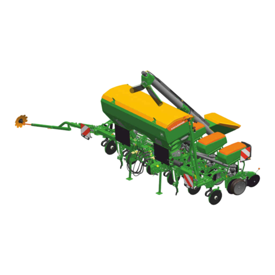
Precea 4500-2CC Lighting and identification for road travel Loading board Filling auger Seeding unit Running gear Fertiliser coulter SmartCenter Shelf compartment for the collapsible bucket and scale 10 Suction baskets Compressed air fan MG6149-EN-GB | J.1 | 18.10.2022 | © AMAZONE... -
Page 27: Implement Overview
Lighting and identification for road travel Shelf compartment for the collapsible bucket and Wheel mark eradicator scale Parking supports 3-point mounting frame Frame ballasting Container for implement documents and other tools 10 Fertiliser hopper Track marker MG6149-EN-GB | J.1 | 18.10.2022 | © AMAZONE... - Page 28 Implement overview CMS-I-00003903 Precea 4500-2 Frame profile Wheel mark eradicator Hose cabinet 3-point mounting frame Frame ballasting Parking supports Shelf compartment for the collapsible bucket and Lighting and identification for road travel scale MG6149-EN-GB | J.1 | 18.10.2022 | © AMAZONE...
-
Page 29: Function Of The Implement
Depending on the requirements, the implement can be fitted with special equipment. Alternatively, the fertiliser can also be carried in a front-mounted hopper. A hose package connects the front-mounted hopper to the rear-mounted implement. MG6149-EN-GB | J.1 | 18.10.2022 | © AMAZONE... -
Page 30: Special Equipment
Hydraulic shifted tramline Hydraulic coulter pressure system Contact force regulation Calibration kit 4.4 Protective equipment CMS-T-00001764-B.1 4.4.1 Universal joint shaft guard CMS-T-00002011-A.1 Universal joint shaft guard cone Universal joint shaft guard CMS-I-00001936 MG6149-EN-GB | J.1 | 18.10.2022 | © AMAZONE... -
Page 31: Fertiliser Metering Drive
1 . CMS-I-00001937 4.4.2.2 Electric metering drive CMS-T-00002014-A.1 Drive guard Electric metering drive CMS-I-00001938 4.4.3 Transport lock CMS-T-00002015-A.1 The transport lock 1 prevents the hydraulic telescopic frame parts from extending unintentionally. CMS-I-00001939 MG6149-EN-GB | J.1 | 18.10.2022 | © AMAZONE... -
Page 32: Warning Symbols
4 | Product description Warning symbols 4.5 Warning symbols CMS-T-00001765-D.1 4.5.1 Position of the warning symbols CMS-T-00001766-C.1 CMS-I-00002031 CMS-I-00002255 MG6149-EN-GB | J.1 | 18.10.2022 | © AMAZONE... - Page 33 4 | Product description Warning symbols CMS-I-00003976 CMS-I-00003975 MG6149-EN-GB | J.1 | 18.10.2022 | © AMAZONE...
-
Page 34: Layout Of The Warning Symbols
Make sure that there is nobody standing in the danger area. MD 082 Risk of falling from tread surfaces and platforms Do not let anybody ride on the implement. Do not let anybody climb onto the driving implement. CMS-I-000081 MG6149-EN-GB | J.1 | 18.10.2022 | © AMAZONE... - Page 35 MD095 Risk of accident due to non-compliance with the instructions in this operating manual Before your work on or with the implement, read and understand the operating manual. CMS-I-000138 MG6149-EN-GB | J.1 | 18.10.2022 | © AMAZONE...
- Page 36 Actuate the tractor hydraulic system only from the designated work station. CMS-I-000139 MD 100 Risk of accidents due to improperly attached lifting gear Only attach the lifting gear at the marked positions. CMS-I-000089 MG6149-EN-GB | J.1 | 18.10.2022 | © AMAZONE...
- Page 37 CMS-I-00004027 MD 155 Risk of accident and machine damage during transport due to improperly secured machine Only attach the lashing belts at the marked lashing positions for transporting the machine. CMS-I-00000450 MG6149-EN-GB | J.1 | 18.10.2022 | © AMAZONE...
-
Page 38: Rating Plate On The Implement
PTO shaft or a hydraulic CMS-I-00001943 motor. The overpressure is set through the fan speed. Depending on the implement equipment, the overpressure is displayed by a pressure gauge or the control terminal. MG6149-EN-GB | J.1 | 18.10.2022 | © AMAZONE... -
Page 39: Variable Telescoping
Each grain singling unit has its own seed hopper. The seed flows through the inlet opening in the grain singling unit. MG6149-EN-GB | J.1 | 18.10.2022 | © AMAZONE... -
Page 40: Singling Disc
The marking on the singling discs provides information on the number of holes 3 and the hole diameter of the singling disc. The ejection wheel 4 releases jammed seed and ensures that the singling discs are clean. CMS-I-00001947 MG6149-EN-GB | J.1 | 18.10.2022 | © AMAZONE... -
Page 41: Pretec Mulch Seeding Coulter
3 . The fertiliser can therefore be applied in the fertiliser furrow 2 or in the seed belt 1 . The exhaust air 4 is discharged near the ground. CMS-I-00007255 MG6149-EN-GB | J.1 | 18.10.2022 | © AMAZONE... -
Page 42: Depth Control Wheels
The furrow former and the catch roller must be adapted to the operating conditions. CMS-I-00001955 4.11 Fertiliser hopper CMS-T-00001985-C.1 Depending on the implement or configuration, the fertiliser hopper contains 950 or 1250 litres. The MG6149-EN-GB | J.1 | 18.10.2022 | © AMAZONE... -
Page 43: Fertec Twin Coulter
The FerTeC Twin coulters are used on ploughed soils or for mulch seeding. The fertiliser placement depth is adjustable. The distance from the seeding coulter is determined by the coulter mount. The distance is of 60 mm. MG6149-EN-GB | J.1 | 18.10.2022 | © AMAZONE... -
Page 44: Filling Auger
Liquid fertiliser connection Liquid fertiliser outlet CMS-I-00002728 4.13 Filling auger CMS-T-00001986-B.1 The filling auger facilitates the filling procedure for the fertiliser hopper. The filling auger is driven by the tractor's hydraulic system. MG6149-EN-GB | J.1 | 18.10.2022 | © AMAZONE... -
Page 45: Micropellet Spreader
Micropellet spreader Micropellet metering unit Bottom flap Drive Sliding shutter Micropellet hopper Hopper cover CMS-I-00002590 MG6149-EN-GB | J.1 | 18.10.2022 | © AMAZONE... - Page 46 Application in the seed furrow, for insecticide and micro-fertiliser applications. CMS-I-00003850 PreTeC coulter without closer Application on the soil surface, for slug pellet or herbicide applications. Application in the seed furrow, for insecticide and micro-fertiliser applications. CMS-I-00003849 MG6149-EN-GB | J.1 | 18.10.2022 | © AMAZONE...
-
Page 47: Lighting
Rear lights and brake lights Red reflectors Yellow reflector Lateral warning signs CMS-I-00001977 NOTE Depending on the national regulations. Lighting to the front Warning signs Side marker lights White reflector Yellow reflector CMS-I-00001979 MG6149-EN-GB | J.1 | 18.10.2022 | © AMAZONE... -
Page 48: Work Lights
4.16.1 Radar sensor CMS-T-00001778-B.1 On electric drives, the radar sensor records the working speed. The working speed is used to determine the worked area and the required speed for the metering drives. CMS-I-00002221 MG6149-EN-GB | J.1 | 18.10.2022 | © AMAZONE... -
Page 49: Low Level Sensors
In conjunction with SmartControl, the scrapers are controlled automatically. By means of the opto-sensor monitoring, gaps or doubles are detected and the scraper bar position is adjusted. This automatically reduces gaps and doubles. CMS-I-00001917 MG6149-EN-GB | J.1 | 18.10.2022 | © AMAZONE... -
Page 50: Threaded Cartridge
CMS-T-00004156-B.1 With the TwinTerminal, the following functions can be executed: Calibrate the spread rate Emptying the implement Communication with the control terminal Enter the calibration parameters Enter the collected seed quantity CMS-I-00003079 MG6149-EN-GB | J.1 | 18.10.2022 | © AMAZONE... -
Page 51: Technical Data
2.7 m to 4.8 m 2.7 m to 4.8 m Centre of gravity distance, Short mounting frame 80 cm 80 cm depending on the Long mounting frame 1.08 m 1.08 m equipment MG6149-EN-GB | J.1 | 18.10.2022 | © AMAZONE... -
Page 52: Permissible Payload
The maximum spread rate depends on the metered material. The maximum spread rate is based on a working speed of 15 km/h. With an electric drive, the spread rate can be adjusted via the forward speed. MG6149-EN-GB | J.1 | 18.10.2022 | © AMAZONE... -
Page 53: Micropellet Metering Unit
Micropellet hopper 17 l 5.5 Coulters CMS-T-00005568-C.1 5.5.1 PreTeC mulch seeding coulter CMS-T-00005570-C.1 NOTE The maximum placement depth serves as a reference value. The actual value can only be determined during field operation. MG6149-EN-GB | J.1 | 18.10.2022 | © AMAZONE... -
Page 54: Fertec Twin Coulter
200 kg 3 cm to 12 cm coupled seeding coulter. 5.6 Row spacings CMS-T-00002366-E.1 NOTE It is possible to subsequently convert the number of rows. For more information, contact your specialist workshop. MG6149-EN-GB | J.1 | 18.10.2022 | © AMAZONE... -
Page 55: Mounting Category
5.8 Working speed CMS-T-00002367-D.1 NOTE High spread rates can prevent the maximum working speed from being reached. Metering drives Recommended speed range Mechanical 2 km/h to 12 km/h Electric 2 km/h to 15 km/h MG6149-EN-GB | J.1 | 18.10.2022 | © AMAZONE... -
Page 56: Performance Characteristics Of The Tractor
The emission sound pressure level mainly depends on the vehicle used. 5.11 Drivable slope inclination CMS-T-00002297-E.1 Across the slope On left in direction of travel 15 % On right in direction of travel 15 % MG6149-EN-GB | J.1 | 18.10.2022 | © AMAZONE... -
Page 57: Lubricants
Retinax A 5.13 Gear oil CMS-T-00003834-B.1 Manufacturer Gear oil WINTERSHALL Wintal UG22 WTL-HM, ex-factory FUCHS Renolin MR5 VG22 5.14 Chain oil CMS-T-00005469-B.1 Chain oil Non-saponifiable mineral-based chain oil according to IS0 VG 68 MG6149-EN-GB | J.1 | 18.10.2022 | © AMAZONE... -
Page 58: Preparing The Machine
Total weight of front-mounted implement or front ballast Permissible total weight of rear-mounted implement or rear ballast Distance between the centre of gravity of the front-mounted implement or the front ballast and the centre of the front axle MG6149-EN-GB | J.1 | 18.10.2022 | © AMAZONE... - Page 59 T b 0,2 T b Vmin Vmin Vmin CMS-I-00000513 2. Calculate the actual front axle load. × × - × G a b T b G c + d Vtat Vtat Vtat CMS-I-00000516 MG6149-EN-GB | J.1 | 18.10.2022 | © AMAZONE...
- Page 60 Tyre load according to according to capacity for two tractor operating calculation tractor tyres manual ≤ Minimum front ballasting ≤ Total weight ≤ ≤ Front axle load ≤ ≤ Rear axle load MG6149-EN-GB | J.1 | 18.10.2022 | © AMAZONE...
-
Page 61: Adjusting The 3-Point Mounting Frame
6.3 Preparing the universal joint shaft CMS-T-00005128-A.1 1. Have the length of the universal joint shaft adjusted by a specialist workshop. 2. Have the universal joint shaft installed by a specialist workshop. MG6149-EN-GB | J.1 | 18.10.2022 | © AMAZONE... -
Page 62: Coupling The Implement
6.4.2 Coupling the supply lines to the front hopper CMS-T-00010803-A.1 1. Connect the plug for the ISOBUS line 1 to the front hopper. 2. Connect the supply lines 2 to the conveyor hoses of the front hopper. CMS-I-00007399 MG6149-EN-GB | J.1 | 18.10.2022 | © AMAZONE... -
Page 63: Attaching The Lower Link Ball Sleeves
CMS-T-00002086-A.1 1. Insert the top link pin 1 together with the ball sleeve 2 in the bottom holes. 2. Secure the top link pin 1 with a linch pin 3 . CMS-I-00001871 MG6149-EN-GB | J.1 | 18.10.2022 | © AMAZONE... -
Page 64: Coupling The Universal Joint Shaft
Stickers are applied on the implement for the markings, which illustrate the respective hydraulic functions. The tractor control unit is used with different types of actuation, depending on the hydraulic function: CMS-I-00000121 MG6149-EN-GB | J.1 | 18.10.2022 | © AMAZONE... - Page 65 Section Double-acting Retract Yellow Track marker Lifting Single-acting Increase Blue Frame ballasting Double-acting Reduce Beige Filling auger Switching on Single-acting Fan hydraulic motor Switching on Single-acting Pressure relief through pressureless return flow. MG6149-EN-GB | J.1 | 18.10.2022 | © AMAZONE...
- Page 66 Install the supplied coupling sleeve on the pressureless hydraulic oil return. 1. Depressurise the hydraulic system between the tractor and the implement using the tractor control unit. 2. Clean the hydraulic plugs. MG6149-EN-GB | J.1 | 18.10.2022 | © AMAZONE...
-
Page 67: Coupling The Isobus Or Control Computer
1. Insert the plug 1 for the power supply. 2. Route the power supply cable with sufficient freedom of movement and without chafing or pinching points. 3. Check the lighting on the implement for proper function. CMS-I-00001048 MG6149-EN-GB | J.1 | 18.10.2022 | © AMAZONE... -
Page 68: Coupling The 3-Point Mounting Frame
6.4.10 Raising the jacks CMS-T-00001838-A.1 To relieve the jacks, raise the implement. 2. Pull out the spring cotter pin 1 . 3. Hold the jack firmly. 4. Remove the pin 2 . CMS-I-00002003 MG6149-EN-GB | J.1 | 18.10.2022 | © AMAZONE... -
Page 69: Operation Without Front Hopper
CMS-I-00002002 6.4.11 Operation without front hopper CMS-T-00008281-A.1 If the implement should be used without the front hopper, install the terminating resistor 1 on the signal cable 2 for the front hopper. CMS-I-00005657 MG6149-EN-GB | J.1 | 18.10.2022 | © AMAZONE... -
Page 70: Preparing The Implement For Operation
If the conveyor hoses are sagging, fasten the fertiliser hoses. When the implement sections have reached the end position, release the pull rope and move the "green" tractor control unit to the neutral position. MG6149-EN-GB | J.1 | 18.10.2022 | © AMAZONE... -
Page 71: Adjusting The Working Position Sensor
Do no walk on the hopper cover. Keep the cover seal and sealing surface clean. 1. Open the fastener 2 . 2. Press the hopper cover 3 down. CMS-I-00001886 3. Unlock the 1 fastener. MG6149-EN-GB | J.1 | 18.10.2022 | © AMAZONE... -
Page 72: Filling The Fertiliser Hopper
The transport vehicle carrying the fertiliser is standing on a level surface 1. Determine the payload of the implement and axles loads of the tractor. 2. Couple the implement to the tractor. MG6149-EN-GB | J.1 | 18.10.2022 | © AMAZONE... - Page 73 The guard screen and function screen in the fertiliser hopper are closed. Only a closed guard screen and function screen can prevent fertiliser clumps and/or foreign objects from entering the fertiliser hopper and clogging the metering unit. MG6149-EN-GB | J.1 | 18.10.2022 | © AMAZONE...
- Page 74 If possible, let the fertiliser run directly into the filling CMS-I-00001894 funnel. 9. Switch on the "beige 1" tractor control unit at 32 l/ min. MG6149-EN-GB | J.1 | 18.10.2022 | © AMAZONE...
- Page 75 The guard screen and function screen in the fertiliser hopper are closed. Only a closed guard screen and function screen can prevent fertiliser clumps and/or foreign objects from entering the fertiliser hopper and clogging the metering unit. MG6149-EN-GB | J.1 | 18.10.2022 | © AMAZONE...
- Page 76 When the fertiliser hopper is full, slowly switch off the filling auger with the ball valve. 10. Switch off the "beige" tractor control unit. MG6149-EN-GB | J.1 | 18.10.2022 | © AMAZONE...
-
Page 77: Preparing The Micropellet Spreader For Operation
1. Open the fastener 2 . 2. Press the hopper cover 3 down. CMS-I-00002595 3. Unlock the 1 fastener. 4. Open the hopper cover 1 . 5. Fill the micropellet hopper. CMS-I-00002598 MG6149-EN-GB | J.1 | 18.10.2022 | © AMAZONE... - Page 78 2. Insert the unlocking tool 2 into the metering unit cover 1 . 3. Unlock the metering unit cover on the metering housing 3 . 4. Open the metering unit cover. CMS-I-00002582 MG6149-EN-GB | J.1 | 18.10.2022 | © AMAZONE...
- Page 79 2 kg/ha to wheel Silver grey Slug pellets 10 kg/ha 3 cm³ Metering Micro- 10 kg/ha to wheel Green fertiliser 35 kg/ha 12 cm³ 10. Insert the desired metering roller into the roller cage. MG6149-EN-GB | J.1 | 18.10.2022 | © AMAZONE...
- Page 80 6.5.5.3 Changing the application point CMS-T-00003633-C.1 PreTeC mulch seeding coulter with closer Application in the closing seed furrow, optionally with targeted outlet or diffuser. Application in the seed furrow, optionally with targeted outlet or diffuser. CMS-I-00002579 MG6149-EN-GB | J.1 | 18.10.2022 | © AMAZONE...
- Page 81 2. Move the diffuser 2 to the desired position. If the desired position cannot be set, Loosen the bolts 3 . 3. Move the diffuser to the desired position. 4. Tighten the bolts. CMS-I-00002837 MG6149-EN-GB | J.1 | 18.10.2022 | © AMAZONE...
-
Page 82: Determining The Setting Parameters
Green 16 mm 16 mm 16 mm 16 mm 5 mbar Squas Opal 45 mbar ± 4 mm F / G Green 20 mm 20 mm 20 mm 16 mm green 5 mbar MG6149-EN-GB | J.1 | 18.10.2022 | © AMAZONE... - Page 83 1. The setting parameters can be found in the table. To adjust the grain singling, see "Adjusting the grain singling unit". To adjust the PreTeC coulter, see "Adjusting the PreTeC coulter". MG6149-EN-GB | J.1 | 18.10.2022 | © AMAZONE...
-
Page 84: Adjusting The Fan Speed
45 mbar ± 5 mbar To correct the fan pressure, Adjust the tractor PTO shaft speed. To monitor the fan pressure, refer to the ISOBUS operating manual. Read the fan pressure on the pressure gauge. MG6149-EN-GB | J.1 | 18.10.2022 | © AMAZONE... - Page 85 "Configuring the fan speed monitoring" in the ISOBUS operating manual refer to "Configuring the fan speed monitoring" in the control computer operating manual Read the fan pressure on the pressure gauge. MG6149-EN-GB | J.1 | 18.10.2022 | © AMAZONE...
-
Page 86: Preparing The Track Marker For Operation
6.4 m working width can only be marked in the tractor track. CMS-I-00001215 Unit Designation Calculated values Number of seeding coulters Row spacing Track marker length, track marker marks at the centre of the tractor MG6149-EN-GB | J.1 | 18.10.2022 | © AMAZONE... - Page 87 CMS-I-00001216 Unit Designation Calculated values Number of seeding coulters Row spacing Track marker length, track marker marks in the tractor track Tractor track width MG6149-EN-GB | J.1 | 18.10.2022 | © AMAZONE...
- Page 88 4 of the track marker disc 4 to CMS-I-00003875 the desired position. To adjust the pitch of the track marker disc, turn the shaft of the track marker disc to the desired position. MG6149-EN-GB | J.1 | 18.10.2022 | © AMAZONE...
-
Page 89: Preparing The Wheel Mark Eradicator For Operation
Increased wear of the wheel mark eradicator bracket When the overload safety is triggered at short intervals, reduce the working depth. Change to a wheel mark eradicator coulter that is easy to pull. MG6149-EN-GB | J.1 | 18.10.2022 | © AMAZONE... - Page 90 The tractor and implement are secured Tightening torque: 160 Nm 1. Release the clamp connection 1 . 2. Move the wheel mark eradicator bracket 2 to the desired position. 3. Tighten the clamp connection. CMS-I-00001908 MG6149-EN-GB | J.1 | 18.10.2022 | © AMAZONE...
- Page 91 2 on the tool carrier. 4. Install the bolts. 5. Install the nuts and tighten them. To check the setting, drive for 30 m at working speed and then check the work pattern. MG6149-EN-GB | J.1 | 18.10.2022 | © AMAZONE...
-
Page 92: Setting Up The Speed Sensor On The Implement
Determine the grain size of the seed with the multi- placement tester. 1. Put the seed in the reference holes 1 . If the seed lies loosely on the reference hole, read the hole diameter. CMS-I-00001217 MG6149-EN-GB | J.1 | 18.10.2022 | © AMAZONE... - Page 93 3. Expose 11 grains in one row. 4. Place the multi-placement tester horizontally on the ground. 5. Measure 10 grain spacings with the ruler 1 . 6. Calculate the average grain spacing. ® Ab10 Ab10 Ab1-10 Ab1-10 CMS-I-00002066 MG6149-EN-GB | J.1 | 18.10.2022 | © AMAZONE...
-
Page 94: Adjusting The Grain Singling Unit
6.5.12 Adjusting the grain singling unit CMS-T-00005516-D.1 6.5.12.1 Changing the singling disc CMS-T-00005572-C.1 1. Secure the tractor and implement. 2. Open the locks 1 . 3. Remove the cover 2 . CMS-I-00001909 MG6149-EN-GB | J.1 | 18.10.2022 | © AMAZONE... - Page 95 Remove the bolt 4 . 7. Install the orange filling block 3 in the mount 8. Install the bolt. CMS-I-00003937 9. For use in rapeseed, beets, or sorghum, remove the cap 1 . MG6149-EN-GB | J.1 | 18.10.2022 | © AMAZONE...
- Page 96 The points 1 and 3 are no longer aligned. CMS-I-00001911 NOTE The sealing wax dot 1 indicates a factory setting. 16. Check the sealing wax dot. If the sealing wax dot has been broken, contact your specialist workshop. CMS-I-00005636 MG6149-EN-GB | J.1 | 18.10.2022 | © AMAZONE...
- Page 97 23. Install the narrow hole covering roller 2 . 24. Put on the nut. CMS-I-00003868 25. Align the guide pin 1 . 26. Close the cover 2 . 27. Close the locks. CMS-I-00001913 MG6149-EN-GB | J.1 | 18.10.2022 | © AMAZONE...
- Page 98 D / E G / H E / F / G B / C E / F / G F / G position 1. Move the sliding shutter 1 to the desired position. CMS-I-00001915 MG6149-EN-GB | J.1 | 18.10.2022 | © AMAZONE...
- Page 99 6.5.12.3 Changing the opto-sensor and shot channel CMS-T-00005387-B.1 NOTE The opto-sensor must be adapted to the respective operating conditions. 1. Uncouple the ISOBUS line. 2. Remove the spring cotter pin 1 . CMS-I-00003814 MG6149-EN-GB | J.1 | 18.10.2022 | © AMAZONE...
- Page 100 5. Remove the bolts 1 . 6. Remove the spacer plate 2 . CMS-I-00003816 7. Disconnect the plug connection 3 . 8. Move the opto-sensor 1 down. 9. Remove the gasket 2 . CMS-I-00003817 MG6149-EN-GB | J.1 | 18.10.2022 | © AMAZONE...
- Page 101 "Determining the setting parameters". 12. Install the desired opto-sensor 1 . CMS-I-00002826 13. Move the opto-sensor 1 up. 14. Put on the gasket 2 . 15. Establish the plug connection 3 . CMS-I-00003817 MG6149-EN-GB | J.1 | 18.10.2022 | © AMAZONE...
- Page 102 23. Restart the implement. CMS-I-00003814 6.5.12.4 Adjusting the scraper mechanically CMS-T-00001896-C.1 NOTE The adjustment of the scraper must be adapted to the respective operating conditions. The optimum adjustment can only be determined during field operation. MG6149-EN-GB | J.1 | 18.10.2022 | © AMAZONE...
-
Page 103: Changing The Seed Spread Rate
4. Check the adjustment of the scraper on the field after driving a short distance. 6.5.13 Changing the seed spread rate CMS-T-00001884-H.1 6.5.13.1 Manually calculating the grain spacing CMS-T-00003838-C.1 Formula symbol Designation Grains G/ha Spread rate per hectare Row width m MG6149-EN-GB | J.1 | 18.10.2022 | © AMAZONE... - Page 104 See "Changing the seed spread rate" in the ISOBUS operating manual 6.5.13.2.2 Determining the working speed CMS-T-00002251-G.1 NOTE The specified values are reference values. They are based on a constant power supply of at least 12 volt. MG6149-EN-GB | J.1 | 18.10.2022 | © AMAZONE...
- Page 105 15 km/h 15 km/h 12.8 km/h 12 km/h 14 k/m² 15 km/h 15 km/h 14.9 km/h 11.9 km/h 11.1 km/h 15 k/m² 15 km/h 15 km/h 13.9 km/h 11.1 km/h 10.4 km/h MG6149-EN-GB | J.1 | 18.10.2022 | © AMAZONE...
- Page 106 7 km/h 5.8 km/h 4.7 km/h 4.4 km/h 72 k/m² 7.3 km/h 6.6 km/h 5.5 km/h 4.4 km/h 4.1 km/h 76 k/m² 6.9 km/h 6.3 km/h 5.2 km/h 4.2 km/h 3.9 km/h MG6149-EN-GB | J.1 | 18.10.2022 | © AMAZONE...
- Page 107 7.8 km/h 6.3 km/h 5.9 km/h 80 k/m² 9.9 km/h 8.9 km/h 7.5 km/h 6 km/h 5.6 km/h The maximum working speed for the desired spread rate can be read from the table. MG6149-EN-GB | J.1 | 18.10.2022 | © AMAZONE...
- Page 108 "Determining the grain spacing". Depending on the gear wheel in the leading wheel drive and the desired grain spacing, determine the gear ratio for the leading wheel drive from the table. CMS-I-00002868 MG6149-EN-GB | J.1 | 18.10.2022 | © AMAZONE...
- Page 109 "Running in the pulses". When the determined pulses per 100 m differs from the values below, the desired grain spacing must be calculated manually. = Pulses per 100 m Gear wheel Z=15 Z=30 MG6149-EN-GB | J.1 | 18.10.2022 | © AMAZONE...
- Page 110 = Pulses per 100 m, see table above = Determined pulses per 100 m 5. Manually calculate the desired grain spacing. 6. Read the gear ratio for the manually calculated grain spacing from the table. MG6149-EN-GB | J.1 | 18.10.2022 | © AMAZONE...
- Page 111 "Determining the grain spacing", refer to the AmaCheck operating manual, "Determining the grain spacing". With the desired grain spacing, determine the gear ratio for the trailing wheel drive from the table. CMS-I-00002790 MG6149-EN-GB | J.1 | 18.10.2022 | © AMAZONE...
- Page 112 = 485 pulses per 100 m = Determined pulses per 100 m 4. Manually calculate the desired grain spacing. 5. Read the gear ratio for the manually calculated grain spacing from the table. MG6149-EN-GB | J.1 | 18.10.2022 | © AMAZONE...
- Page 113 8. Put the removed gear wheel in the parking CMS-I-00002653 position 2 . 9. Install the cotter pin. 10. Install the desired gear wheel on the drive shaft. 11. Install the washer. 12. Install the cotter pin. MG6149-EN-GB | J.1 | 18.10.2022 | © AMAZONE...
- Page 114 22. Hold the lever. CMS-I-00002651 23. Close the cover 1 against the spring pressure. To lock the cover, Continue actuating the lever 3 . The cover will be locked on the chain tensioner CMS-I-00002647 MG6149-EN-GB | J.1 | 18.10.2022 | © AMAZONE...
- Page 115 3. Push the cover 1 to the side. 4. Swivel up the cover. CMS-I-00002646 5. Loosen the bolt 1 . If the parking position can be tipped far enough, take the chain extension 2 from the parking position. CMS-I-00005656 MG6149-EN-GB | J.1 | 18.10.2022 | © AMAZONE...
- Page 116 To tighten the drive chain, put the tension spring 2 around the retaining pin CMS-I-00002650 To ensure that the tightened drive chain runs on all of the gear wheels, turn the drive wheel. CMS-I-00002648 MG6149-EN-GB | J.1 | 18.10.2022 | © AMAZONE...
-
Page 117: Adjusting The Pretec Mulch Seeding Coulter
If the soil is moved completely, the press roller does not have enough fine soil to close the seed furrow. CAUTION The star clearers are subject to wear. This can cause sharp edges. Wear protective gloves. MG6149-EN-GB | J.1 | 18.10.2022 | © AMAZONE... - Page 118 2. Secure the tractor and implement. 3. Hold the clod clearer by the handle 1 . 4. Remove the linch pin 2 . 5. Pull out the positioning pin 3 . CMS-I-00002086 MG6149-EN-GB | J.1 | 18.10.2022 | © AMAZONE...
- Page 119 The rigid cutting discs allow the seeding unit to run smoothly on soils with coarse surface structures. The rigid cutting discs cut through plant residues and clear the area of the seeding coulter. MG6149-EN-GB | J.1 | 18.10.2022 | © AMAZONE...
- Page 120 6.5.14.4 Adjusting the seed placement depth CMS-T-00005825-C.1 NOTE The adjustment of the seed placement depth must be adapted to the respective operating conditions. The optimum adjustment can only be determined during field operation. MG6149-EN-GB | J.1 | 18.10.2022 | © AMAZONE...
- Page 121 A . 6. Lock the setting lever in the grid. To check the setting, drive for 30 m at working speed and "check the seed placement depth". MG6149-EN-GB | J.1 | 18.10.2022 | © AMAZONE...
- Page 122 ISOBUS operating manual "Adjusting the coulter pressure". To check the setting, drive for 30 m at working speed and "check the seed placement depth". MG6149-EN-GB | J.1 | 18.10.2022 | © AMAZONE...
- Page 123 CMS-T-00001932-E.1 Disc closer Disc closer setting lever CMS-I-00001962 The disc closers are used on ploughed or mulched soils. They cover the seed furrow with fine soil. The disc closer pressure is adjustable. MG6149-EN-GB | J.1 | 18.10.2022 | © AMAZONE...
- Page 124 Move the disc closers in the tracks to the desired position. 6. Lock the setting lever in the grid. CMS-I-00001926 To check the setting, drive for 30 m at working speed and then check the work pattern. MG6149-EN-GB | J.1 | 18.10.2022 | © AMAZONE...
- Page 125 Increase the press roller Heavy soils pressure: + Reduce the press roller Light soils pressure: - CMS-I-00002743 1. Lift the implement. 2. Secure the tractor and implement. 3. Unlock the setting lever 1 . MG6149-EN-GB | J.1 | 18.10.2022 | © AMAZONE...
- Page 126 13. Remove the bolt 1 with the press roller. 14. Move the press roller 3 with the setting bushing 2 to the desired position. 15. Install the press roller with bolts. 16. Tighten the lock nut. MG6149-EN-GB | J.1 | 18.10.2022 | © AMAZONE...
- Page 127 "Changing the catch roller". 6.5.14.10 Adjusting the depth control wheel scraper CMS-T-00001936-E.1 IMPORTANT Damage to the depth control wheel due to abrasion by the scraper To check the distance, rotate the depth control wheel MG6149-EN-GB | J.1 | 18.10.2022 | © AMAZONE...
- Page 128 CMS-I-00002700 2. Put a suitable support 1 under the coulter. To move the locking mechanism to the locking position, slowly lower the implement. The coulter is fixed in the parking position. CMS-I-00002706 MG6149-EN-GB | J.1 | 18.10.2022 | © AMAZONE...
- Page 129 The coulter is lowered into working position. CMS-I-00002699 6.5.14.12 Adjusting the catch roller scraper CMS-T-00003720-D.1 IMPORTANT Damage to the depth control wheel due to abrasion by the scraper To check the distance, rotate the depth control wheel MG6149-EN-GB | J.1 | 18.10.2022 | © AMAZONE...
- Page 130 To select the catch roller, CMS-I-00002876 see "Determining the setting parameters". 8. Install the desired catch roller. To install the suitable furrow former for the catch roller, see "Changing the furrow former". MG6149-EN-GB | J.1 | 18.10.2022 | © AMAZONE...
-
Page 131: Creating Tramlines
To take the calibration buckets out of CMS-I-00001932 the parking position on implements with mechanical fan drive, pull out the calibration buckets individually to the side on the left and right. MG6149-EN-GB | J.1 | 18.10.2022 | © AMAZONE... - Page 132 To enter the spread rate for the fertiliser on the control terminal, refer to the ISOBUS software operating manual, CMS-I-00001956 "Calibrating the spread rate for fertiliser or micropellets". NOTE To prevent overflowing of the calibration bucket, monitor the fill level. MG6149-EN-GB | J.1 | 18.10.2022 | © AMAZONE...
- Page 133 8 km/h 6.7 km/h 5.3 km/h 5 km/h 700 kg/ha 8.4 km/h 7.5 km/h 6 km/h 5 km/h 4.7 km/h 740 kg/ha 7.9 km/h 7.1 km/h 5.9 km/h 4.8 km/h 4.5 km/h MG6149-EN-GB | J.1 | 18.10.2022 | © AMAZONE...
- Page 134 5.2 kg/ha 4.3 kg/ha 3.5 kg/ha 3.2 kg/ha 740 kg/ha 5.5 kg/ha 4.9 kg/ha 4.1 kg/ha 3.3 kg/ha 3.1 kg/ha 780 kg/ha 5.2 kg/ha 4.7 kg/ha 3.9 kg/ha 3.1 kg/ha 2.9 kg/ha MG6149-EN-GB | J.1 | 18.10.2022 | © AMAZONE...
-
Page 135: Calibrating The Mechanically Driven Fertiliser Metering
= Working width in m = Number of rows ´ = Row width in cm ´ 75 4 5 ´ CMS-I-00002685 1. Determine the special working width of the implement with the equation above. MG6149-EN-GB | J.1 | 18.10.2022 | © AMAZONE... - Page 136 To take the calibration buckets out of CMS-I-00001932 the parking position on implements with mechanical fan drive, pull out the calibration buckets individually to the side on the left and right. MG6149-EN-GB | J.1 | 18.10.2022 | © AMAZONE...
- Page 137 6. Take the operating tool from the parking position 7. Put the operating tool on the gear shaft 2 . CMS-I-00002785 MG6149-EN-GB | J.1 | 18.10.2022 | © AMAZONE...
- Page 138 14. Turn the operating tool counterclockwise by the desired number of turns. NOTE To prevent overflowing of the calibration bucket, monitor the fill level. Stop the calibration and empty the bucket if necessary. MG6149-EN-GB | J.1 | 18.10.2022 | © AMAZONE...
- Page 139 "Determining the gearbox position with the calculator disc". 20. Repeat the calibration until the desired quantity is metered. NOTE If the desired spread rate is not reached, contact your specialist workshop for more information. MG6149-EN-GB | J.1 | 18.10.2022 | © AMAZONE...
- Page 140 3 from the calculator disc. NOTE Set the gearbox setting lever between the scale positions 20 and 80. 3. Set the gearbox setting lever to the value read from the disc. MG6149-EN-GB | J.1 | 18.10.2022 | © AMAZONE...
-
Page 141: Changing The Application Rate For Liquid Fertiliser
= Fertiliser content in percent ´ 55 100 ϱ = Density in kg/l 153 5 ´ 1 28 1. Determine the application rate for the fertiliser using the equation. ´ ´ CMS-I-00002734 MG6149-EN-GB | J.1 | 18.10.2022 | © AMAZONE... - Page 142 4. Move the valve 1 to the desired position. Since the flow rate depends on the applied material, check the setting by calibrating. Observe the operating manual for the liquid fertiliser tank CMS-I-00002735 MG6149-EN-GB | J.1 | 18.10.2022 | © AMAZONE...
-
Page 143: Adjusting The Placement Depth On The Coupled Fertiliser Coulter
The operating conditions affect the correct setting. The adjustment of the fertiliser coulter must be adapted to the respective operating conditions. Check the adjustment of the fertiliser coulter on the field after driving a short distance. MG6149-EN-GB | J.1 | 18.10.2022 | © AMAZONE... - Page 144 Hold the fertiliser coulter in the desired position, CMS-I-00001934 Tighten the bolts. 6. Make the same adjustment for all fertiliser coulters. Put the fertiliser placement depth in the tracks in the desired position. MG6149-EN-GB | J.1 | 18.10.2022 | © AMAZONE...
-
Page 145: Adjusting The Fertiliser Application Point
For maximum effect of the frame ballasting, the implement must be coupled to the highest top link point on the tractor side. MG6149-EN-GB | J.1 | 18.10.2022 | © AMAZONE... - Page 146 "green 2" tractor control unit and set a pressure of 30 bar. actuate the "blue 2" tractor control unit and set a pressure of 30 bar. The frame ballasting is resting on the lower links. MG6149-EN-GB | J.1 | 18.10.2022 | © AMAZONE...
-
Page 147: Adjusting The Filling Auger
Unlock the setting lever 1 . 7. Move the setting lever to the desired position. CMS-I-00002030 In the end position, the outlet is closed. 8. The setting lever must lock in the setting grid. MG6149-EN-GB | J.1 | 18.10.2022 | © AMAZONE... -
Page 148: Using The Loading Board
3. Climb onto the loading board 2 using the ladder. 4. After use, swivel the ladder 1 up and put it in the parking position. 5. Secure the ladder in the parking position with the cotter pin. CMS-I-00002745 MG6149-EN-GB | J.1 | 18.10.2022 | © AMAZONE... -
Page 149: Telescoping 6 Rows Variably
50 cm position. 11. telescope the implement in. The third coulter pushes on the fourth coulter. On the opposite side, the fifth coulter pushes on the fourth coulter. MG6149-EN-GB | J.1 | 18.10.2022 | © AMAZONE... - Page 150 22. Seal the seeding coulter wiring harness 1 with a dust cap. To lift the fourth seeding coulter, see "Using the coulter raised position". CMS-I-00003830 24. Connect the ISOBUS to the tractor. 25. Restart the implement. MG6149-EN-GB | J.1 | 18.10.2022 | © AMAZONE...
- Page 151 Telescopic frames with the short protrusion 1 can be telescoped from 80 to 50 cm. CMS-I-00003845 1. Raise the implement. To set the row spacing to 50 cm, telescope the implement in. MG6149-EN-GB | J.1 | 18.10.2022 | © AMAZONE...
- Page 152 If the conveyor hoses are sagging, fasten the fertiliser hoses. When the implement sections have reached the end position, release the pull rope and move the "green" tractor control unit to the neutral position. MG6149-EN-GB | J.1 | 18.10.2022 | © AMAZONE...
- Page 153 6. Move the opposite linch pin in the slotted link to CMS-I-00003839 the desired position between the fourth and fifth coulter. 7. Move the opposite linch pin in the slotted link to the desired position between the fifth and sixth coulter. MG6149-EN-GB | J.1 | 18.10.2022 | © AMAZONE...
-
Page 154: Telescoping 7 Rows Variably
4. Move the linch pin to the desired position between the first and second coulter. CMS-I-00002810 5. Move the opposite linch pin to the desired position between the sixth and seventh coulter. MG6149-EN-GB | J.1 | 18.10.2022 | © AMAZONE... - Page 155 15. Move the opposite linch pin to the desired position between the fifth and sixth coulter. 16. Telescope the implement out. CMS-I-00002808 The desired row spacing is adjusted between all of the coulters. MG6149-EN-GB | J.1 | 18.10.2022 | © AMAZONE...
- Page 156 6.5.26.2 Adjusting the row spacing between 60 and 42.9 cm CMS-T-00003842-C.1 CAUTION There are crushing and shear points between the implement sections and the implement. When folding or unfolding the implement sections, never reach into the crushing area. MG6149-EN-GB | J.1 | 18.10.2022 | © AMAZONE...
- Page 157 Actuate the pull rope and actuate the "green" tractor control unit. When the implement sections have reached their end position, the conveyor hoses to the fertiliser coulters may not sag. MG6149-EN-GB | J.1 | 18.10.2022 | © AMAZONE...
-
Page 158: Adjusting The Coulter Pressure In The Track
When the coulter pressure beside the tracks is adjusted, the coulter pressure in the tracks is increased by the set value. To check the setting after driving a short distance: See "Checking the placement depth". MG6149-EN-GB | J.1 | 18.10.2022 | © AMAZONE... -
Page 159: Adjusting The Running Gear Height
3 links. To adjust the length of the drive chain, see "Replacing the gear wheel in the leading wheel drive". NOTE For more information, please contact your AMAZONE customer service. MG6149-EN-GB | J.1 | 18.10.2022 | © AMAZONE... -
Page 160: Installing A Seed Row
2 . 6. Fasten 2 load handling devices on the coulter body 1 . CMS-I-00004137 7. Guide the tilted coulter 1 along the frame 2 . 8. Lower the coulter. CMS-I-00004136 MG6149-EN-GB | J.1 | 18.10.2022 | © AMAZONE... - Page 161 "Coupling the air and fertiliser supply". To put the desired coulter into operation, see "Coupling the energy supply". If the implement is equipped with a hydraulic coulter pressure system, see "Coupling the hydraulic supply". MG6149-EN-GB | J.1 | 18.10.2022 | © AMAZONE...
- Page 162 3. Lower the implement and move the three-point hydraulic system of tractor into float position. The coulter pressure cylinders retract and the coulter pressure is relieved. CMS-I-00007310 4. Switch off the fan. 5. Secure the tractor and implement. MG6149-EN-GB | J.1 | 18.10.2022 | © AMAZONE...
- Page 163 14. Disconnect the connection 3 . 15. Remove the long hydraulic hose 1 . CMS-I-00007202 16. Install the original hydraulic hose between the coulters. To replace the second line repeat steps 1 to 3. MG6149-EN-GB | J.1 | 18.10.2022 | © AMAZONE...
- Page 164 When the hydraulic coulter pressure system has been vented, close the valve 3 . 23. Install the fastener 1 . 24. Install the bolt 2 . MG6149-EN-GB | J.1 | 18.10.2022 | © AMAZONE...
- Page 165 6.5.29.5 Establishing the air and fertiliser supply on the distributor head CMS-T-00005489-D.1 To restore the fertiliser flow on implements with distributor heads: actuate the lever 1 . The fertiliser is conveyed into the fertiliser coulter. CMS-I-00003960 MG6149-EN-GB | J.1 | 18.10.2022 | © AMAZONE...
- Page 166 5. Seal the free connection cable with a dust cap after the row conversion. 6. Install the conveyor hose 1 on the fertiliser coulter 3 . 7. Install the clamp 2 . CMS-I-00003920 MG6149-EN-GB | J.1 | 18.10.2022 | © AMAZONE...
-
Page 167: Removing Seed Rows
The contact force sensor can be recognised by the signal processing 2 . CMS-I-00003921 Conversion Removing recommendation From 6 to 4 rows Rows 2 and 5 From 12 to 8 rows Rows 3, 5, 8 and 10 MG6149-EN-GB | J.1 | 18.10.2022 | © AMAZONE... - Page 168 3. Lower the implement and move the three-point hydraulic system of tractor into float position. The coulter pressure cylinders retract and the coulter pressure is relieved. CMS-I-00007310 4. Switch off the fan. MG6149-EN-GB | J.1 | 18.10.2022 | © AMAZONE...
- Page 169 13. Install connectors 5 between the hydraulic hoses. CMS-I-00007201 14. Install sealing caps 1 from the sealing kit on the T-piece 2 . To convert the hydraulic supply of the second line repeat steps 1 to 3. MG6149-EN-GB | J.1 | 18.10.2022 | © AMAZONE...
- Page 170 When the hydraulic coulter pressure system has been vented, close the valve 3 . 24. Install the fastener 1 . 25. Install the bolt 2 . MG6149-EN-GB | J.1 | 18.10.2022 | © AMAZONE...
- Page 171 To interrupt the fertiliser flow on implements with distributor heads: actuate the lever 1 . The fertiliser is then conveyed back into the corrugated tube and the conveyor air is diverted close to the ground. CMS-I-00003959 MG6149-EN-GB | J.1 | 18.10.2022 | © AMAZONE...
- Page 172 For a conversion from 12 to 8 rows connect the setting motors for rows 3 to 12 to the wiring harness according to the table. 6. Seal the free connection cable with a dust cap. MG6149-EN-GB | J.1 | 18.10.2022 | © AMAZONE...
- Page 173 6.5.30.6 Removing the PreTeC mulch seeding coulter CMS-T-00005475-C.1 REQUIREMENTS Energy supply disconnected Hydraulic supply disconnected Air and fertiliser supply disconnected 1. Remove the bolts 1 . 2. Remove the coulter bracket 2 . CMS-I-00004135 MG6149-EN-GB | J.1 | 18.10.2022 | © AMAZONE...
- Page 174 "Adjusting the seed placement depth" CMS-I-00005134 To move the catch roller to position see "Adjusting the catch roller" 12. Lift the implement. 13. Position the transport dolly 2 under the coulter to be removed. MG6149-EN-GB | J.1 | 18.10.2022 | © AMAZONE...
- Page 175 21. Push the coulters into the desired position. For telescopic coulters Tighten the bolts to 160 Nm minus 180°, For non-telescopic coulters CMS-I-00002039 Tighten the bolts to 200 Nm. 23. Connect the ISOBUS to the tractor. MG6149-EN-GB | J.1 | 18.10.2022 | © AMAZONE...
-
Page 176: Preparing The Machine For Road Travel
1. Fold the transport lock 1 into the locked position. CMS-I-00001940 2. Pull out the pins 1 and lock them. 3. Push in the section tube 2 completely. 4. Secure the section tube with pins. CMS-I-00001941 MG6149-EN-GB | J.1 | 18.10.2022 | © AMAZONE... -
Page 177: Lifting The Implement
1. Lift the implement with the 3-point power lift of the tractor. 2. Check the connections of the hydraulic lines and the power supply. 3. Switch off control terminal. 4. Switch off the work lights. 5. Lock the tractor control units. MG6149-EN-GB | J.1 | 18.10.2022 | © AMAZONE... -
Page 178: Telescoping The Implement Sections
"green" tractor control unit to the neutral position. 6.6.4 Locking the tractor control units CMS-T-00006337-C.1 Depending on the equipment, the tractor control units are locked mechanically or electrically. MG6149-EN-GB | J.1 | 18.10.2022 | © AMAZONE... -
Page 179: Using The Machine
The speed of the singling discs is immediately adjusted to normal changes in speed. To check the seed placement depth and grain spacing after the first 30 m, see "Checking the seed placement depth" and "Checking the grain spacing". MG6149-EN-GB | J.1 | 18.10.2022 | © AMAZONE... -
Page 180: Turning On The Headlands
The fan is running WARNING Specific coulters are hydraulically shifted The shifting procedure cannot be stopped. Only a bit of space remains between the coulters. Keep people out of the danger area of the implement. MG6149-EN-GB | J.1 | 18.10.2022 | © AMAZONE... - Page 181 "Configuring the tramline control". To shift the coulters, drive into the upcoming tramline with the implement lifted. If the coulters have not reached the end position, slowly drive up with the implement lowered. MG6149-EN-GB | J.1 | 18.10.2022 | © AMAZONE...
-
Page 182: Eliminating Faults
Replace the lighting supply line. Stopping of one or several singling The fuse for the electric drive is see page 180 discs. defective. Fuse for the mechanical drive is see page 181 defective. MG6149-EN-GB | J.1 | 18.10.2022 | © AMAZONE... - Page 183 181 housing is too high. worn. To replace the furrow former, The seed furrow is unstable or The furrow former is worn. does not maintain its shape. see "Changing the furrow former". MG6149-EN-GB | J.1 | 18.10.2022 | © AMAZONE...
- Page 184 If the grain shape and dressing cause the formation of bridges, improve the sliding capacity of the seed by adding 1.6 g of talc per 1 kg of seed. MG6149-EN-GB | J.1 | 18.10.2022 | © AMAZONE...
- Page 185 Offset installation is not possible in conjunction with disc closers. 1. Unscrew the nut 1 and remove it. 2. Remove the press roller. To increase the throughput on the press rollers, install the press roller with offset. CMS-I-00002041 MG6149-EN-GB | J.1 | 18.10.2022 | © AMAZONE...
- Page 186 Stopping of one or several singling discs CMS-T-00003677-B.1 CMS-I-00002695 MG6149-EN-GB | J.1 | 18.10.2022 | © AMAZONE...
- Page 187 If the brushes of the filling block are worn, the seed does not flow back into the storage area 2 within the filling block. To replace the defective filling block, see "Changing the singling disc" contact your specialist workshop. CMS-I-00005635 MG6149-EN-GB | J.1 | 18.10.2022 | © AMAZONE...
-
Page 188: Parking The Machine
The implement is coupled to the tractor The tractor and implement are secured NOTE The parking position for the chute is in the hopper cover for row 1. 1. Take out the chute 1 . CMS-I-00001888 MG6149-EN-GB | J.1 | 18.10.2022 | © AMAZONE... - Page 189 5. Put the collection bucket 2 under the chute. CMS-I-00001997 Hook the collection bucket 2 onto the chute. 6. Put the collection bucket 2 under the chute. 7. Release the lock 1 until the points 2 are aligned. CMS-I-00001910 MG6149-EN-GB | J.1 | 18.10.2022 | © AMAZONE...
- Page 190 11. Turn the lock 1 beyond the notch 2 . The points 3 are no longer aligned. CMS-I-00001911 12. Close the cover 2 . NOTE Pay attention to the guide pin 1 . 13. Close the locks. CMS-I-00001913 MG6149-EN-GB | J.1 | 18.10.2022 | © AMAZONE...
-
Page 191: Emptying The Seed Hopper Through The Residual Quantity Flap
The flap 2 is opened and the residual quantity is collected. When the residual quantity has been collected, park the chute back into the hopper cover. 6. Close the flap. 7. Lock the locking spring. CMS-I-00001996 MG6149-EN-GB | J.1 | 18.10.2022 | © AMAZONE... -
Page 192: Emptying The Fertiliser Metering Unit
2 . To move the bottom flap lever to the emptying position, press and hold the lock button 3 and push it down 4 . 8. Take out the residual quantity. CMS-I-00001994 MG6149-EN-GB | J.1 | 18.10.2022 | © AMAZONE... -
Page 193: Emptying The Micropellet Hopper
9.5 Emptying the micropellet hopper CMS-T-00003603-A.1 1. Close the the sliding shutter 1 on the micropellet hopper. CMS-I-00002586 2. Move the switchover flap 1 to position A . CMS-I-00002580 MG6149-EN-GB | J.1 | 18.10.2022 | © AMAZONE... - Page 194 The micropellets are collected in the collapsible bucket. CMS-I-00002576 When the residual quantity has be fully collected, move the bottom flap lever 1 back into working position. 7. Open the sliding shutter 2 completely. CMS-I-00002622 MG6149-EN-GB | J.1 | 18.10.2022 | © AMAZONE...
-
Page 195: Relieving The Hole Covering Rollers
The implement is coupled to the tractor The tractor and implement are secured 1. Open the locks 1 . 2. Remove the cover 2 . CMS-I-00001909 3. Release the lock 1 until the points 2 are aligned. CMS-I-00001910 MG6149-EN-GB | J.1 | 18.10.2022 | © AMAZONE... -
Page 196: Parking The Wheel Mark Eradicator
Depending on the implement equipment, the topmost position can differ. IMPORTANT Damage to the wheel mark eradicator Before parking the implement on solid ground, move the wheel mark eradicators into parking position. MG6149-EN-GB | J.1 | 18.10.2022 | © AMAZONE... -
Page 197: Parking The Pretec Coulter
6. Secure the locking pin with the linch pin. CMS-I-00000942 9.8 Parking the PreTeC coulter CMS-T-00001920-D.1 In the P position, the lowered depth control wheels protect the furrow formers 1 and catch roller 2 . CMS-I-00001999 MG6149-EN-GB | J.1 | 18.10.2022 | © AMAZONE... -
Page 198: Putting Down The Jacks
2. Hold the jack firmly. 3. Remove the pin 2 . CMS-I-00002002 4. Take the jack 1 out of the parking position. 5. Peg the jack 1 in the support position. CMS-I-00002000 MG6149-EN-GB | J.1 | 18.10.2022 | © AMAZONE... -
Page 199: Disconnecting The Supply Lines From The Front-Mounted Hopper
9.11 Disconnecting the supply lines from the front hopper CMS-T-00010804-A.1 1. Disconnect the plug for the ISOBUS line 1 from the front hopper. 2. Disconnect the supply lines 2 from the conveyor hoses of the front hopper. CMS-I-00007399 MG6149-EN-GB | J.1 | 18.10.2022 | © AMAZONE... -
Page 200: Uncoupling The Isobus Or Control Computer
3. Disconnect the hydraulic hose lines 1 . 4. Put the dust caps on the hydraulic sockets. CMS-I-00001065 5. Hang the hydraulic hose lines 1 in the hose cabinet. CMS-I-00001250 MG6149-EN-GB | J.1 | 18.10.2022 | © AMAZONE... -
Page 201: Uncoupling The Power Supply
2. Release the top link 1 . 3. Uncouple the top link 1 from the implement. 4. Release the lower links 2 . 5. Uncouple the lower links 2 from the implement from the tractor seat. CMS-I-00001249 MG6149-EN-GB | J.1 | 18.10.2022 | © AMAZONE... -
Page 202: Uncoupling The Universal Joint Shaft
2 . CMS-I-00001935 9.17 Conserving the drive shaft CMS-T-00003870-A.1 To ensure that the drive shafts can be smoothly telescoped, seal the shafts with a non-adhesive conservation agent after washing. CMS-I-00002825 MG6149-EN-GB | J.1 | 18.10.2022 | © AMAZONE... -
Page 203: Repairing The Machine
206 bolts Checking the frame connection tightening torque see page 206 Checking the coulter connection tightening torque see page 207 Checking the running gear connection tightening see page 207 torque MG6149-EN-GB | J.1 | 18.10.2022 | © AMAZONE... -
Page 204: Coulter
PreTeC mulch seeding coulter Checking and replacing the cutting disc on the FerTeC see page 203 Twin coulter Checking and replacing the inner scraper on the see page 204 FerTeC Twin coulter MG6149-EN-GB | J.1 | 18.10.2022 | © AMAZONE... -
Page 205: Checking And Replacing The Cutting Discs On The Pretec Mulch Seeding Coulter
9. Put on and tighten the bolts on the bearing seat. 10. Install new cutting discs. To ensure that the cutting discs touch slightly, adjust the spacing of the cutting discs with the spacer discs 4 . MG6149-EN-GB | J.1 | 18.10.2022 | © AMAZONE... -
Page 206: Adjusting The Cutting Disc Distance On The Pretec Mulch Seeding Coulter
5. Install spacer discs that are not required on the opposite side of the cutting disc bearing with the central bolt. 6. Put on and tighten the central bolt. MG6149-EN-GB | J.1 | 18.10.2022 | © AMAZONE... -
Page 207: Adjusting The Cutting Disc Drive On The Pretec Mulch Seeding Coulter
3 and 4 . Spacer discs that are not needed are fastened to CMS-I-00002016 the depth control wheel arm Fasten the discs on the opposite side using the bolt. MG6149-EN-GB | J.1 | 18.10.2022 | © AMAZONE... -
Page 208: Checking And Replacing The Closer
If the diameter of the cutting discs is less than 320 mm, replace the worn cutting discs 1 . 3. Remove the bolts 2 . 4. Replace worn cutting discs with new cutting discs. 5. Install the bolts. CMS-I-00005361 MG6149-EN-GB | J.1 | 18.10.2022 | © AMAZONE... -
Page 209: Checking And Replacing The Cutting Disc On The Fertec Twin Coulter
11. Install spacer discs that are not required on the opposite side of the cutting disc bearing with the central bolt. 12. Put on and tighten the central bolt. 13. Install the dust caps. MG6149-EN-GB | J.1 | 18.10.2022 | © AMAZONE... -
Page 210: Adjusting The Cutting Disc Distance On The Fertec Twin Coulter
10.1.9 Checking and replacing the inner scraper on the FerTeC Twin coulter CMS-T-00002381-D.1 INTERVAL Every 100 operating hours Every 3 months The inner scrapers ensure smooth coulter running and are subject to wear. MG6149-EN-GB | J.1 | 18.10.2022 | © AMAZONE... -
Page 211: Checking The Wheel Bolt Tightening Torque
10.1.10 Checking the wheel bolt tightening torque CMS-T-00002382-D.1 INTERVAL After initial operation Every 50 operating hours Wheel bolt tightening Tyres torque Tyres 6.5/80x15-AS 325 Nm Tyres 26x12-12 AS 325 Nm Check the wheel bolt tightening torque. MG6149-EN-GB | J.1 | 18.10.2022 | © AMAZONE... -
Page 212: Checking The Tightening Torque For The Radar Sensor Bolts
Check the tightening torque on the radar sensor. CMS-I-00002600 10.1.12 Checking the frame connection tightening torque CMS-T-00002384-B.1 INTERVAL After initial operation Every 12 months Check the tightening torque on both sides. 120 Nm CMS-I-00002037 MG6149-EN-GB | J.1 | 18.10.2022 | © AMAZONE... -
Page 213: Checking The Coulter Connection Tightening Torque
The tightening torques must be checked when the coulters are unloaded. CMS-I-00002039 10.1.14 Checking the running gear connection tightening torque CMS-T-00002386-B.1 INTERVAL After initial operation Every 12 months Check the tightening torque on both sides. 160 Nm CMS-I-00002038 MG6149-EN-GB | J.1 | 18.10.2022 | © AMAZONE... -
Page 214: Checking The Tyre Inflation Pressure
After initial operation Every 50 operating hours weekly 1. Check the hydraulic hose lines for damage, such as chafing point, cuts, tears and deformation. 2. Check the hydraulic hose lines for leaks. MG6149-EN-GB | J.1 | 18.10.2022 | © AMAZONE... -
Page 215: Cleaning The Fan Rotor
When most of the water has escaped through the air distributor, run the fan for about 5 minutes. The air supply is blown dry. 4. Switch off the fan. CMS-I-00002024 5. Close the water drain on the air distributor. MG6149-EN-GB | J.1 | 18.10.2022 | © AMAZONE... -
Page 216: Cleaning The Cyclone Separator
5. Install the cover with the wing nut. CMS-I-00002765 6. Fasten the suction cage with the clips. 10.1.20 Cleaning the suction basket CMS-T-00003836-A.1 INTERVAL Every 10 operating hours daily Clean the suction baskets 1 . CMS-I-00002793 MG6149-EN-GB | J.1 | 18.10.2022 | © AMAZONE... -
Page 217: Cleaning The Filling Auger
7. Thoroughly clean the filling auger 3 with a water jet. 8. Put on the installation flap. 9. Put on the bolts and tighten them. 10. Install the cover. CMS-I-00002027 11. Put on the nuts and tighten them. MG6149-EN-GB | J.1 | 18.10.2022 | © AMAZONE... -
Page 218: Cleaning The Fertiliser Hopper
2 . 9. Remove residues or foreign objects from the fertiliser hopper. 10. Close the protective screen. 11. Park the unlocking tool on the fertiliser hopper. CMS-I-00002028 MG6149-EN-GB | J.1 | 18.10.2022 | © AMAZONE... - Page 219 To move the calibration flap lever into working position, press and hold the lock button and push it upwards. To move the bottom flap lever into working position, press and hold the lock button and push it CMS-I-00001932 upwards. MG6149-EN-GB | J.1 | 18.10.2022 | © AMAZONE...
-
Page 220: Cleaning The Fertiliser Metering Unit
5. Remove residues or foreign objects from the metering housing. 6. Close the metering unit cover 3 . 7. Park the unlocking tool from the threaded cartridge or the parking position in the fertiliser hopper. MG6149-EN-GB | J.1 | 18.10.2022 | © AMAZONE... -
Page 221: Cleaning The Micropellet Metering Unit
4. Insert the unlocking tool 2 into the metering unit cover 1 . 5. Unlock the metering unit cover on the metering housing 3 . 6. Open the metering unit cover. CMS-I-00002582 MG6149-EN-GB | J.1 | 18.10.2022 | © AMAZONE... - Page 222 CMS-I-00002584 10. Clean the metering housing 11. Actuate the switchover flap 4 several times. 12. Actuate the bottom flap lever 1 several times. 13. Clean the outlets 2 and 3 . CMS-I-00002577 MG6149-EN-GB | J.1 | 18.10.2022 | © AMAZONE...
-
Page 223: Adjusting The Micropellet Metering Unit Bottom Flap
Every 12 months 1. Move the bottom flap lever 3 into working position. To adjust the pre-tension, the bolt head 1 should be 9 -10 mm above the clamping lever 2 . CMS-I-00002581 MG6149-EN-GB | J.1 | 18.10.2022 | © AMAZONE... -
Page 224: Clean The Singling Unit
4. Release the lock 1 until the points 2 are aligned. CMS-I-00001910 5. remove the singling disc 1 from the drive hub. 6. Clean the singling unit housing. 7. Install the singling disc. CMS-I-00001912 MG6149-EN-GB | J.1 | 18.10.2022 | © AMAZONE... -
Page 225: Cleaning The Opto-Sensor
10.1.27 Cleaning the opto-sensor CMS-T-00002393-C.1 INTERVAL Every 50 operating hours as required 1. Disconnect the ISOBUS connection to the tractor. 2. Open the locks 1 . 3. Remove the cover 2 . CMS-I-00001909 MG6149-EN-GB | J.1 | 18.10.2022 | © AMAZONE... - Page 226 7. Rinse the opto-sensor with clear fresh water. 8. Install the singling disc. 9. Install the cover. To remove stubborn contamination, remove the opto-sensor. Remove the spring cotter pin 1 . CMS-I-00003814 MG6149-EN-GB | J.1 | 18.10.2022 | © AMAZONE...
- Page 227 13. Remove the bolts 1 . 14. Remove the spacer plate 2 . CMS-I-00003816 15. Disconnect the plug connection 3 . 16. Move the opto-sensor 1 down. 17. Remove the gasket 2 . CMS-I-00003817 MG6149-EN-GB | J.1 | 18.10.2022 | © AMAZONE...
- Page 228 21. Rinse the opto-sensor with clear fresh water. 22. Insert the opto-sensor 1 . CMS-I-00002826 23. Move the opto-sensor 1 up. 24. Put on the gasket 2 . 25. Establish the plug connection 3 . CMS-I-00003817 MG6149-EN-GB | J.1 | 18.10.2022 | © AMAZONE...
- Page 229 29. Swivel the shot channel under the opto-sensor. CMS-I-00003815 30. Install the shot channel with the spring cotter pin 31. Establish the ISOBUS connection to the tractor. 32. Restart the implement. CMS-I-00003814 MG6149-EN-GB | J.1 | 18.10.2022 | © AMAZONE...
-
Page 230: Cleaning The Distributor Head
2. Loosen the knurled screws 1 . 3. Remove the cover 2 . CMS-I-00003957 4. Clean all of the outlets 1 . 5. Install the cover. 6. Tighten the knurled screws. CMS-I-00003958 MG6149-EN-GB | J.1 | 18.10.2022 | © AMAZONE... -
Page 231: Checking The Wheel Mark Eradicator Coulter
CMS-I-00001081 the tool carrier is less than 15 mm, replace the wheel mark eradicator coulter 2 . To replace the wheel mark eradicator coulter, See section "Changing the wheel mark eradicator coulter". MG6149-EN-GB | J.1 | 18.10.2022 | © AMAZONE... -
Page 232: Lubricating The Machine
Only grease the implement with the lubricants listed in the technical data. CMS-I-00002270 Press the dirty grease completely out of the bearings. MG6149-EN-GB | J.1 | 18.10.2022 | © AMAZONE... -
Page 233: Overview Of Lubrication Points
10 | Repairing the machine Lubricating the machine 10.2.1 Overview of lubrication points CMS-T-00002350-B.1 CMS-I-00002082 Every 50 operating hours CMS-I-00002080 MG6149-EN-GB | J.1 | 18.10.2022 | © AMAZONE... -
Page 234: Lubricating The Roller Chains
After the first 10 operating hours Every 50 operating hours at the end of the season 1. Remove the bolts 2 . 2. Push the cover 1 to the side. 3. Swivel up the cover. CMS-I-00002646 MG6149-EN-GB | J.1 | 18.10.2022 | © AMAZONE... - Page 235 4. Lubricate the roller chain 1 from the inside going out. 5. Check chain tensioner 2 for ease of movement. CMS-I-00003884 6. Install the cover. 7. Install the bolts and washers. CMS-I-00002645 MG6149-EN-GB | J.1 | 18.10.2022 | © AMAZONE...
-
Page 236: Lubricating The Roller Chain In The Interchangeable Wheel Gear
2. Lubricate the roller chain 1 from the inside going out. 3. Check chain tensioner 2 for ease of movement. CMS-I-00003885 4. Actuate the lever 1 . The drive chain will be tightened. 5. Hold the lever. CMS-I-00002651 MG6149-EN-GB | J.1 | 18.10.2022 | © AMAZONE... -
Page 237: Lubricating The Roller Chain In The Trailing Wheel Drive
10.3.3 Lubricating the roller chain in the trailing wheel drive CMS-T-00005450-B.1 INTERVAL After the first 10 operating hours Every 50 operating hours at the end of the season 1. Remove the bolts 2 . 2. Remove the cover 1 . CMS-I-00002721 MG6149-EN-GB | J.1 | 18.10.2022 | © AMAZONE... - Page 238 3. Lubricate the roller chain 2 from the inside going out. 4. Check chain tensioner 1 for ease of movement. CMS-I-00003887 5. Install the cover. 6. Install the bolts and washers. CMS-I-00002720 MG6149-EN-GB | J.1 | 18.10.2022 | © AMAZONE...
-
Page 239: Lubricating The Roller Chain On The Mechanical Metering Drive
3. Lubricate the roller chain 1 from the inside going out. 4. Check chain tensioner 2 for ease of movement. CMS-I-00003886 5. Install the cover 1 . 6. Install the bolts. CMS-I-00002723 MG6149-EN-GB | J.1 | 18.10.2022 | © AMAZONE... -
Page 240: Lubricating The Roller Chain On The Central Fertiliser Metering Drive
2. Remove the cover 2 . CMS-I-00004157 3. Lubricate the roller chain 1 from the inside going out. 4. Check chain tensioner 2 for ease of movement. 5. Install the cover. 6. Install the bolts. CMS-I-00004156 MG6149-EN-GB | J.1 | 18.10.2022 | © AMAZONE... -
Page 241: Lubricating The Roller Chain On The Electric Agitator Shaft Drive
2. Remove the cover 2 . CMS-I-00004157 3. Lubricate the roller chain 1 from the inside going out. 4. Check chain tensioner 2 for ease of movement. 5. Install the cover. 6. Install the bolts. CMS-I-00005365 MG6149-EN-GB | J.1 | 18.10.2022 | © AMAZONE... -
Page 242: Cleaning The Implement
Always maintain a minimum distance of 30 cm between the high-pressure nozzle and the implement. Do not exceed a water pressure of 120 bar. Clean the machine with a high-pressure cleaner or a hot water high-pressure cleaner. MG6149-EN-GB | J.1 | 18.10.2022 | © AMAZONE... -
Page 243: Loading The Implement
The implement has lashing points for slings. For implements with fertiliser hopper, the lashing points are in the fertiliser hopper. CMS-I-00004146 For implements without fertiliser hopper, the lashing points are on the swing arms. CMS-I-00004150 MG6149-EN-GB | J.1 | 18.10.2022 | © AMAZONE... - Page 244 CMS-I-00004146 Improperly attached lifting gear in the fertiliser hopper. REQUIREMENTS Implement is in transport position 1. Attach the slings for lifting on the intended lashing points. 2. Slowly lift the implement. CMS-I-000089 MG6149-EN-GB | J.1 | 18.10.2022 | © AMAZONE...
-
Page 245: Lashing The Implement
11 | Loading the implement Lashing the implement 11.2 Lashing the implement CMS-T-00002196-C.1 The implement has lashing points for securing the load. CMS-I-00004145 CMS-I-00002006 CMS-I-00004150 MG6149-EN-GB | J.1 | 18.10.2022 | © AMAZONE... - Page 246 Lashing the implement CMS-I-00002074 REQUIREMENTS Implement is folded 1. Only attach the lifting gear at the marked positions. 2. Secure the implement in accordance with the regulations to the transport vehicle. CMS-I-00000450 MG6149-EN-GB | J.1 | 18.10.2022 | © AMAZONE...
-
Page 247: Appendix
380 Nm 290 Nm 405 Nm 485 Nm 27 mm M18x1.5 325 Nm 460 Nm 550 Nm 410 Nm 580 Nm 690 Nm 30 mm M20x1.5 460 Nm 640 Nm 770 Nm MG6149-EN-GB | J.1 | 18.10.2022 | © AMAZONE... -
Page 248: Other Applicable Documents
8.4 Nm 242 Nm 20.4 Nm 342 Nm 40.7 Nm 470 Nm 70.5 Nm 589 Nm 12.2 Other applicable documents CMS-T-00001756-C.1 Tractor operating manual ISOBUS software operating manual Control terminal operating manual MG6149-EN-GB | J.1 | 18.10.2022 | © AMAZONE... -
Page 249: Directories
Tractor In this operating manual, the designation tractor is always used, even for other agricultural tractor units. Implements are mounted on the tractor or towed by the tractor. MG6149-EN-GB | J.1 | 18.10.2022 | © AMAZONE... -
Page 250: Index
Adjusting the scraper Closer discs changing checking and replacing on the PreTeC mulch Chain oil seeding coulter Compressed air fan Configuring the tramline control ISOBUS Conserving the drive shaft Contact data Technical editing MG6149-EN-GB | J.1 | 18.10.2022 | © AMAZONE... - Page 251 Front axle load Dimensions calculation Disc closer Front ballasting adjustment calculation Disconnecting the supply lines from the front- Furrow former mounted hopper changing Distributor head cleaning Documents Gear oil Grain spacing manually calculating MG6149-EN-GB | J.1 | 18.10.2022 | © AMAZONE...
- Page 252 Lashing the implement Relieving the hole covering rollers Lifting the implement 171, 237 Uncoupling the universal joint shaft Lighting Parking the machine Emptying the fertiliser metering unit Parking the wheel mark eradicator MG6149-EN-GB | J.1 | 18.10.2022 | © AMAZONE...
- Page 253 Determining the PreTeC mulch seeding coulter 76 Putting down the jacks Determining the singling unit Setting up the speed sensor ISOBUS Rating plate on the implement Shifted tramline Description using Rear axle load Shot channel calculation clogged MG6149-EN-GB | J.1 | 18.10.2022 | © AMAZONE...
- Page 254 Working speed calculation to mark at the centre of the tractor determining Tractor Calculating the required tractor characteristics 52 Tractor control units locking Tramline control preparing for operation MG6149-EN-GB | J.1 | 18.10.2022 | © AMAZONE...
- Page 256 AMAZONEN-WERKE H. DREYER SE & Co. KG Postfach 51 49202 Hasbergen-Gaste Germany +49 (0) 5405 501-0 amazone@amazone.de www.amazone.de MG6149-EN-GB | J.1 | 18.10.2022 | © AMAZONE...
Need help?
Do you have a question about the Precea 4500-2 and is the answer not in the manual?
Questions and answers