Table of Contents
Advertisement
Quick Links
Product overview
6
5
3
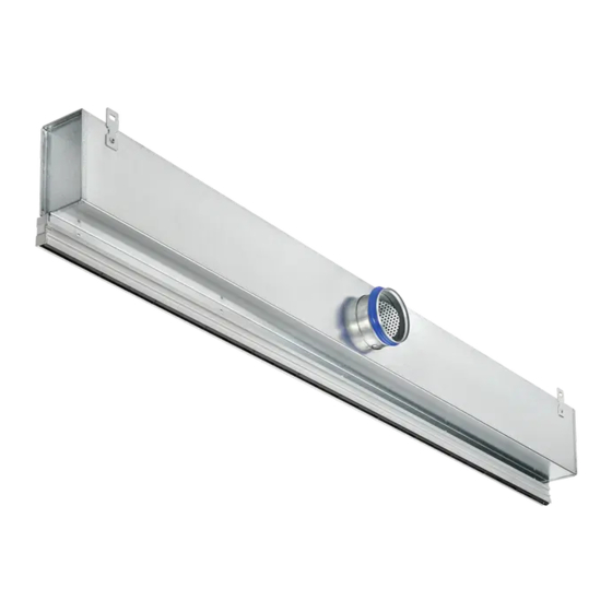
1 TSD diffuser face; 1, 2, 3 or 4 slots
2 Air control blade
3 End plate/angle (optional)
4 Concealed plenum fixing S11 (optional)
5 AKV TSD plenum box
Fig. 1: TSD schematic diagram
Installation instructions
Air diffusers
Slot Diffusers Type TSD
7
4
2
1
Air diffusers Slot Diffusers Type TSD
GB/en
TROX UK
Caxton Way,
Thetford, Norfolk, IP24 3SQ,
UK
Tel: +44 (0) 1842 754545
Fax: +44 (0) 1842 763051
E-mail: info@troxuk.co.uk
http://www.troxuk.co.uk/
9
8
6 Plenum box support hole (11 × 7)
7 Plenum box support bracket (11 × 7)
8 Spigot
9 Spigot damper (optional)
1
Advertisement
Table of Contents

Related Manuals for Trox Technik TSD -3-NF Series


Summary of Contents for Trox Technik TSD -3-NF Series
- Page 1 Installation instructions GB/en TROX UK Caxton Way, Thetford, Norfolk, IP24 3SQ, Tel: +44 (0) 1842 754545 Air diffusers Fax: +44 (0) 1842 763051 E-mail: info@troxuk.co.uk http://www.troxuk.co.uk/ Slot Diffusers Type TSD Product overview 1 TSD diffuser face; 1, 2, 3 or 4 slots 6 Plenum box support hole (11 ×...
-
Page 2: Important Notes
Important notes Important notes Industrial safety helmet Information on the installation manual Industrial safety helmets protect suspended loads, and the This manual enables operating or service personnel effects stationary objects. to correctly install the product described below and to use it safely and efficiently. It is essential that these individuals read and fully Industrial safety glasses understand this manual before starting any work. -
Page 3: Transport And Storage
Transport and storage The installation of air terminal devices in humid Please note: rooms, areas with potentially explosive atmos- Be careful when unloading or moving the pheres or rooms with dust-laden or aggressive air product, and pay attention to the symbols and has to be assessed for each individual case. -
Page 4: Technical Data
Technical data Technical data Dimensions Fig. 2: Dimensions and spigot arrangement for construction ZH/AH TSD type ØD [mm] TSD15-1 174.0 145.5 181.5 TSD15-2 181.5 180.0 191.5 40/75* TSD15-3 191.5 214.5 211.5 TSD15-4 211.5 249.0 236.5 C*: Increase spigot length for M, MC damper options A**: Values for plenum with 'e' = 0 Air diffusers Slot Diffusers Type TSD... - Page 5 Technical data TSD type ØD [mm] TSD20-1 174.0 150.5 191.5 TSD20-2 191.5 190.0 211.5 40/75* TSD20-3 211.5 229.5 236.5 TSD20-4 236.5 269.0 C*: Increase spigot length for M, MC damper options A**: Values for plenum with 'e' = 0 Fig. 3: Dimensions and spigot arrangement for construction ZV/AV TSD type ØD [mm]...
- Page 6 Technical data TSD type ØD [mm] TSD20-1 150.5 TSD20-2 190.0 229.5 TSD20-3 TSD20-4 269.0 Fig. 4: Dimensions for construction RA TSD type B [mm] 1 Slot 2 Slot 3 Slot 4 Slot TSD15-1 43.5 78.0 112.5 147.0 48.5 88.0 127.5 167.0 TSD15-2 A = B + 44mm...
- Page 7 Technical data TSD**-3-FL TSD**-3-NF TSD**-3-P TSD20-3-PL Fig. 5: Border options and dimensions TSD type P [mm] 1 Slot 2 Slot 3 Slot 4 Slot TSD20-1 TSD15 56.0 90.5 125.0 159.5 TSD20 61.0 101.5 140.0 179.5 TSD20-2 TSD15 69.0 103.5 138.0 172.5 TSD20 74.0...
- Page 8 Technical data End Plate TSDxx-P-Px End Plate TSD20-PL-PL2 End Plate TSDxx-NF-Px End Plate TSDxx-NF-Lx End Angle TSDxx-FL-Ax Fig. 6: End cap options and dimensions Ceiling Opening Size [mm] TSD type Width Length 1 Slot 2 Slot 3 Slot 4 Slot TSD20-1 TSD15 57.5...
- Page 9 Technical data Mitred Corner Fig. 7: Mitred corner options and dimensions For dimension 'P', please refer to diffuser dimension pages. Border Type TSD type Angle ° TSD15-1 194.25 263.3 200.75 256.8 188.25 269.3 195.13 197.62 226.2 200.3 223.5 228.7 TSD15-2 194.25 332.3 200.75...
- Page 10 Technical data Weights TSD**...-PL TSD**...-FL/NF/P Nominal length Nominal length Weight (kg) Weight (kg) Number of slots Number of slots 1200 1200 1500 1500 1800 1800 AKV-TSD15-...-ZH-... Nominal length Weight (kg) Number of slots 1200 11.6 10.2 1500 13.5 1800 10.6 11.9 AKV-TSD20-...-ZH-...
-
Page 11: Plenum Installation
Assembly Technical data Ensure that all components are clean before you install them. If necessary, clean them Nominal lengths 300 – 1800 mm, in thoroughly. If you have to interrupt the install- increments of 1mm -ation procedure, protect all openings from the Number of slots 1, 2, 3 or 4 ingress of dust or moisture. - Page 12 Plenums Diffuser installation Use all 4 of the available suspension lugs or at least 4 of the fixing holes on the With the plenum box(es) installed and plenum box, one in each corner. suspended to the correct height, the diffuser can be unpacked ready for installation.
- Page 13 Fixing kits Adjustment screw 1 S11 fixing 2 S11 fixing screws (2 per fixing) Fig. 14: S11 fixing kit with plenum 3 TSD diffuser Install the S11 fasteners (2 or 4) to the Fig. 11: S11 fixing kit installation TSD diffuser to suit the location of the installed plenum box(es).
- Page 14 Plaster-in Installing the diffuser (Linear) Installing the diffuser (Finite) The plaster-in diffuser should be installed Linear diffusers will be supplied into the builder's work opening, retaining the with alignment pins (details on plastic film on the front of the diffuser to page 15) prevent marks during the installation.
-
Page 15: Diffuser Installation
Linear runs The fixings should be installed to the TSD diffuser by the equipment installer. GP fixings should be installed to the TSD diffuser in locations approximately 100mm in from each end of the diffuser WARNING! Overtightening of the fixing screws can result in mechanical failure! –... - Page 16 Fixing kits GP fixings are designed to clamp the diffuser against the project ceiling system (ceiling depth between 1... 40mm). A minimum 25mm clearance should be provided to either side of the opening to facilitate installation with GP fixings. Fig.
- Page 17 Fixing kits Quantity of SB fixings supplied with SB fixings are designed to facilitate support each TSD diffuser is based on the to the building structure via Ø6mm threaded whether the diffuser is supplied rod or wire supports (by others). Fixings are with or without a plenum;...
-
Page 18: Blanking Plates
Blanking plates In addition to bending the blanking plate Installing the blanking plate the plate can be secured to position Blanking plates, if supplied, must be fitted using the screws supplied with the blanking plate, if desired. to the rear of the diffuser before it is installed into the builder's work opening. -
Page 19: Initial Commissioning, Maintenance And Cleaning
Initial commissioning, maintenance and cleaning TSD, apart from the alternating discharge variant, is supplied with the blades in the closed position which need to be set on site by others. Setting the places is a two-hand operation, with hands at both ends of the blade, to avoid deforming the blade. - Page 20 Initial commissioning, maintenance and cleaning Volume flow rate balancing When several diffusers are connected to just one volume flow controller, it may be necessary to bal- ance the volume flow rates. Slot diffusers with plenum box and damper blade (variant -M*): The damper blade can be adjusted even after the diffuser face has been installed.
- Page 21 Initial commissioning, maintenance and cleaning Maintenance and cleaning Please note: The cleaning intervals given in the VDI 6022 standard apply. Clean surfaces with a damp cloth. Use only common household cleaners, do not use any aggressive cleaning agents. Do not use cleaning agents that contain ...
Need help?
Do you have a question about the TSD -3-NF Series and is the answer not in the manual?
Questions and answers