Table of Contents
Advertisement
Advertisement
Table of Contents

Related Manuals for Topcon Ez METER EZ-200


Summary of Contents for Topcon Ez METER EZ-200
- Page 1 INSTRUCTION MANUAL Ez METER...
-
Page 3: Introduction
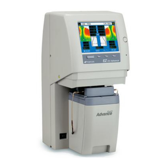
INTRODUCTION Thank you for purchasing the TOPCON EZ-200 Ez Meter. This instrument is used to measure the power of the lenses set in the spectacle frames. This instrument has the following features: • You can measure the power of the spectacle lenses for both eyes simultaneously by means of a simple operation. - Page 4 WORKING ENVIRONMENT Indoor use, maximum altitude: 2,000m Degree of contamination: II (IEC 60664), working temperature range: 5 ~ 35°C Temperature less than 31°C (40°C): linear drop to max. relative humidity of 80% (50%) STORAGE METHOD (without package) 1. ENVIRONMENTAL CONDITIONS Indoor use, maximum altitude: 2,000m Degree of contamination: II (IEC 60664), working temperature range: 5 ~ 40°C Temperature less than 31°C (40°C): linear drop to max.
-
Page 5: Display For Safe Use
DISPLAY FOR SAFE USE To encourage safe and proper use and to prevent danger to the operator and others or potential damage to property, important safety messages are put on the instrument body and inserted into the instruction manual. We suggest that everyone understand the meaning of the following displays, icons and text before reading the "SAFETY CAUTIONS"... -
Page 6: Safety Cautions
SAFETY CAUTIONS WARNINGS Icon Preventive item Page To avoid electric shock, do not attempt disassembling, rebuilding and/or repairs on your own. Ask your dealer for repairs. Do not remove the covers from the front surface, the rear surface, the LCD display unit, etc. You may receive an electric shock. To avoid fire and electric shock, install the instrument in a place free ----- of water and other liquids. -
Page 7: Usage And Maintenance
53. ESCAPE CLAUSES • TOPCON shall not take any responsibility for damage due to fire, earthquakes, actions by third persons and other accidents, or damage due to negligence and misuse by the user and any use under unusual conditions. -
Page 8: Warning Displays And Positions
To ensure safety, the machine provides warning displays. Use the instrument correctly by observing the display instructions. If any of the following display labels are missing, contact your TOPCON dealer or your local Topcon office listed on the back cover of this manual. -
Page 9: Table Of Contents
CONTENTS INTRODUCTION ........................1 DISPLAY FOR SAFE USE ....................3 ICONS ..........................3 SAFETY CAUTIONS ......................4 USAGE AND MAINTENANCE ....................5 ESCAPE CLAUSES ......................5 WARNING DISPLAYS AND POSITIONS ................6 NOMENCLATURE MAIN COMPONENTS ......................9 LCD DISPLAY ........................10 PRINTER OUTPUT ......................15 STANDARD ACCESSORIES ...................17 PREPARATIONS INSTALLING THE INSTRUMENT ..................18 CONNECTING THE POWER CABLE ................19... - Page 10 ELECTROMAGNETIC COMPATIBILITY ................46 SYSTEM CLASSIFICATION ..................... 50 DIMENSIONS AND WEIGHT ...................50 PURPOSE OF USE ......................50 OPERATION PRINCIPLE ....................50 REFERENCE MATERIAL SHAPE OF PLUG ......................51 SYMBOL ...........................51 MAINTENANCE MAINTENANCE ........................52 CLEANING ........................53 DISPOSAL OF PRODUCT ....................55...
-
Page 11: Nomenclature
NOMENCLATURE MAIN COMPONENTS LCD diplay Luminance adjustment volume Power lamp Operation button Lens retainer Shield cover Nose rest pad retainer Frame support Frame retainer Power switch Printer NOMENCLATURE... -
Page 12: Lcd Display
LCD DISPLAY MAIN display (shown in "LARGE FONT") Lens measurement mode (when "AUTO" is selected) Serial No. Frame mode Left eye lens measured values Right eye lens measured values S: Spherical power S: Spherical power C: Cylindricality C: Cylindricality A: Axis angle A: Axis angle ADD: Addition ADD: Addition... - Page 13 "PROGRESSIVE" manual operation display Progressive astigmatic map : Far point Measured values: : Near point S/C/A/ADD Addition graph Inset quantity Distance between far point and near point button: SHIFT button: NEAR POINT Changes far point to near point. Changes the button function. button (or button): Moves the far/near point.
- Page 14 PD input display Left eye hPD Right eye hPD CANCEL button: Ends the PD input display. button/ button: Changes the numerical value. button: Selects and changes the left eye hPD/right eye hPD/CANCEL. MENU display Menu items: Content of each menu: The selected item is The set content is displayed displayed in reverse.
- Page 15 Date/time setting display Year Month Hour Minute button: Ends the date/ button (negative)/ time setting display. button (positive): button: Changes the numerical value. Changes year/month/ day/hour/minute. Print form setting display Format type Print items : Print -- : Do not print button: Ends the print form button/...
- Page 16 Shop name print setting display Character list CANCEL Cancels the set data. Cursor (displayed in reverse) EXIT Ends the shop name print setting display. Printed contents button: button: Sets the character at the Changes the character button and cursor position in the list for list/printed contents.
-
Page 17: Printer Output
PRINTER OUTPUT Example of printer output for MAIN display (shown in "EZ FORMAT") Bar code Date/time Serial No./Instrument No. Left eye measured values: Right eye measured values: S: Spherical power C: Cylindricality S: Spherical power C: Cylindricality A: Axis angle ADD: Addition A: Axis angle ADD: Addition PSM: Horizontal prism/vertical prism PSM: Horizontal prism/vertical prism... - Page 18 Example of printer output for "PROGRESSIVE" display Bar code Date/time Serial No./Instrument No. Left eye measured values: Right eye measured values: S: Spherical power C: Cylindricality S: Spherical power C: Cylindricality A: Axis angle ADD: Addition A: Axis angle ADD: Addition PSM: Horizontal prism/vertical prism PSM: Horizontal prism/vertical prism Inset quantity...
-
Page 19: Standard Accessories
Power cable (1) Fuse (2) Printer paper (2) Printer shaft (1) Silicone cloth (1) Dust cover (1) If any of the standard accessories are not included, contact your local TOPCON office listed on the back cover of this manual. NOMENCLATURE... -
Page 20: Preparations
PREPARATIONS INSTALLING THE INSTRUMENT Don't hold the shield cover at the bottom of the LCD display. The CAUTION instrument may be damaged. To prevent the instrument from tipping over or falling and to avoid CAUTION injury, do not install the instrument on an uneven or unsteady sur- face, including a slope. -
Page 21: Connecting The Power Cable
Remove the protective paper from the cover glass. Protective paper CONNECTING THE POWER CABLE To avoid fire and electric shock in case of leakage, connect the WARNING power plug to a 3-plug AC outlet with proper grounding. CAUTION To avoid electric shock, do not handle the plugs with wet fingers. Make sure that the power switch is set at "OFF"... -
Page 22: Connecting The External Input/Output Terminals
Use the external device complying with IEC60950/IEC60950-1, UL60950/UL60950-1 or UL60601-1. DATA TERMINAL OUT By using RS-232C, this instrument can send data to the TOPCON Compuvision, auto refractometer/auto kerato-refractometer, a personal computer, etc. Connect the connection cable to the DATA TERMINAL OUT terminal on the instrument. - Page 23 Press the button when "MAIN menu" is displayed. PRINT "PRINTER HEAD UP" is displayed on the screen. Remove the printer cover and set the printer paper under the outlet as shown below. Set the rolling direction of the printer paper as shown below. Lever Direction of printer paper...
-
Page 24: Menu Setting
MENU SETTING You can set the contents of "Menu list" on page 23. Press the MODE button when "MAIN display" is shown. Press the button to access the "MENU display". MENU Select an item to be changed with the button or button. - Page 25 When you want to change other menu items, press the button and repeat steps To end a setting, press the button when a menu item is selected. To return the changed data to the original condition, select "EXIT" at the top of the menu items (to be displayed in reverse) and press the button.
- Page 26 MAPPING The astigmatic maps are outputted from the USB port. RS-FORMAT STD1 (CL) Sets the TOPCON STD1 format. (Transferable with CL-100/200) OLD (CL) Sets the TOPCON OLD format. (Transferable with CL-100/200) NEW (CL) Sets the TOPCON NEW format. (Transferable with CL-100/200) STD1 (EZ) Sets the TOPCON STD1 format.
-
Page 27: Setting The Function Button
SETTING THE FUNCTION BUTTON The [FUNCTION] button (third button from the left in the following figure) can be set to the function changing buttons as shown below according to the customer's use frequency. When shipped, it is set at "TRANS (= + / -- button)". -
Page 28: Setting Date/Time
Access the "MENU display" and select "CLEAR" from the menu items. Select "ON" from the menu content items. Press the button. While the menu item is selected, press the button to exit the "MENU display". For the operation of "MENU display", refer to "MENU SETTING" on page 22. When you set "ON"... -
Page 29: Setting Print Form
SETTING PRINT FORM You can set the items to be printed. Access "MENU display" and select "PRINT FORM" from the menu items. Press the button. ("SET" among the menu content items is displayed in reverse.) Press the button to access "print form setting display". Format type Print items : Print... -
Page 30: Setting For Printing The Shop Name
SETTING FOR PRINTING THE SHOP NAME When you print the shop name, it is necessary to set " " for NOTE "NAME SET" in the print form setting procedure. For details, refer to "SETTING PRINT FORM" on page 27. You can print the shop name, comments, etc. (24 characters in 3 lines) Access the "MENU display"... -
Page 31: Setting The Serial No
SETTING THE SERIAL NO. When you print the serial number, it is necessary to set " " for NOTE "SEQ NO." in the print form setting procedure. For details, refer to "SETTING PRINT FORM" on page 27. You can set the serial number for the test spectacles. When shipped, "0001" is set. Access the "MENU display"... -
Page 32: Basic Operations
BASIC OPERATIONS PREPARATION FOR MEASUREMENT TURNING ON THE POWER Don't turn on the power while the frame is set. In initial measure- NOTE ment, an error may occur. If the cover glass is stained, "Dust detection error" may be dis- played in initial measurement. -
Page 33: Setting The Lens Measurement Mode
SETTING THE LENS MEASUREMENT MODE If you set a mode inapplicable to the lens to be measured, you NOTE may not perform measurement or get a correct measured value. You can change the measurement mode according to the type of the lens. •... -
Page 34: Measurement By Auto Mode
MEASUREMENT BY AUTO MODE If the temple or the nose rest pad is deformed or if a broken spec- NOTE tacle frame is measured, you may not perform measurement or get a correct measured value. It is impossible to measure a frame whose vertical width is less NOTE than 22mm with the automatic judgment function. -
Page 35: Measurement By Single Mode
After the measurement is finished, the results are displayed on the LCD display. Then, the frame retainer is released and the shield cover opens. The result of the automatic judgment is shown with the display of "SINGLE", "PROG" or "Bi-F" in the upper left-hand corner of the screen. When measuring a lens whose optical center cannot be specified (e.g. -
Page 36: Measurement By Prog Mode
MEASUREMENT BY PROG MODE If the temple or the nose rest pad is deformed or if a broken spec- NOTE tacle frame is measured, you may not perform measurement or get a correct measured value. If a paint mark remains on a progressive lens, you may not mea- NOTE sure the progressive lens or get a correct measured value. -
Page 37: Measurement By Bi-F Mode
Press the button. MEASURE The frame retainer moves to set the spectacle frames in the measurement position. After the shield cover is closed, measurement starts. While the frame retainer and the shield cover are in operation, you can stop the oper- ation with the button (pause) or the button. -
Page 38: Objective Operations
PRINT The measured values on the screen are printed. DATA OUTPUT WITH RS-232C By using RS-232C, this instrument can send data to the TOPCON Compuvision, auto refractometer/auto kerato-refractometer, a personal computer, etc. Check the connection of DATA TERMINAL OUT. For details on the connection, refer to "DATA TERMINAL OUT" on page 20. -
Page 39: Data Input With Rs-232C
DATA INPUT WITH RS-232C By using RS-232C, this instrument can input the ID number by connecting with the bar code/magnetic card reader, etc. Check the connection of DATA TERMINAL IN. For details on the connection, refer to "DATA TERMINAL IN" on page 20. Set "INPUT/OUTPUT"... - Page 40 Press the button, and the pop-up window to change the function appears. FUNCTION The selected function is displayed in reverse. Press the button to select "PD". Press the button to access "PD input display". Right eye hPD Left eye hPD CANCEL Press the button to display the right eye hPD or the left eye hPD.
-
Page 41: Transpose (Power Conversion)
TRANSPOSE (POWER CONVERSION) Make sure that "MAIN display" appears on the screen. Press the MODE button, and the pop-up window to change the measurement mode appears. Press the button, and the pop-up window to change the function appears. FUNCTION The selected function is displayed in reverse. Press the button to select "TRANS". -
Page 42: Connection To Tm-1/Tm-2
CONNECTION TO TM-1/TM-2 This instrument can display the measurement results by connecting with the TOPCON spectral transmittance meter TM-1/TM-2. When you perform the connection, contact your dealer or your local Topcon office listed on the back cover of this manual. OBJECTIVE OPERATIONS... -
Page 43: Before Requesting Service
BEFORE REQUESTING SERVICE ERROR CODE When the EZ-200 malfunctions, an error code is displayed with the message together. Code Meaning Initial measurement error #0 In initial measurement, the quantity of the bright spots, which have been transmitted through the Hartmann plate, is not normal. -
Page 44: Message
MESSAGE Message Contents PRINTER PAPER END The printer paper is used up. PRINTER HEAD UP The lever is not pushed down. PRINTER THERMAL ERROR The thermal printer is hot because of continuous printing or paper jamming. Halted during initial measurement. You have pressed the [STOP] button during initial measure- Please turn on the power again. -
Page 45: Troubleshooting
If, after following the instructions below, you still cannot restore the instrument to a normal condition or if the problem does not fall into any of the categories below, contact your dealer or your local Topcon office listed on the back cover of this manual. Check List... -
Page 46: Specifications And Performance
SPECIFICATIONS AND PERFORMANCE Measurement range Spherical power: 0 - ±15D (0.25D step) 0 - ±10D for mapping measurement Cylindricality: 0 - ±10D (0.25D step) Axis angle: 1 - 180° ∆ ∆ Prism: 0 - 10 (0.25 step): When hPD 32mm is set. Addition: 0.5D - 10.0D 48 - 80mm:... -
Page 47: Use Ambient Conditions
USE AMBIENT CONDITIONS Installation : Indoors Max. height : 2000m Temperature range : 5 - 35°C Humidity : Max. Relative humidity 80% (without dew condensation) Air pressure : 70 - 106kPa Power voltage change : Less than nominal voltage ±10% Installation category : II Pollution... -
Page 48: Electromagnetic Compatibility
ELECTROMAGNETIC COMPATIBILITY This product conforms to the EMC Standard (IEC 60601-1-2:2004). a) MEDICAL ELECTRICAL EQUIPMENT needs special precautions regarding EMC and needs to be installed and put into service according to the EMC information provided in the ACCOMPANYING DOCUMENTS. b) Portable and mobile RF communications equipment can affect MEDICAL ELECTRICAL EQUIPMENT. - Page 49 Guidance and manufacturer's declaration - electromagnetic immunity The EZ-200 is intended for use in the electromagnetic environment specified below. The cus- tomer or the user of the EZ-200 should assure that it is used in such an environment. Immunity test IEC 60601 Compliance Electromagnetic environment -...
- Page 50 Guidance and manufacturer's declaration - electromagnetic immunity The EZ-200 is intended for use in the electromagnetic environment specified below. The cus- tomer or the user of the EZ-200 should assure that it is used in such an environment. Immunity test IEC 60601 Compliance Electromagnetic environment-...
- Page 51 Recommended separation distance between portable and mobile RF communications equipment and the EZ-200 The EZ-200 is intended for use in an electromagnetic environment in which radiated RF distur- bances are controlled. The customer or the user of the EZ-200 can help prevent electromagnetic interference by maintaining a minimum distance between portable and mobile RF communica- tions equipment (transmitters) and the EZ-200 as recommended below, according to the maxi- mum output power of the communications equipment.
-
Page 52: System Classification
SYSTEM CLASSIFICATION • Type of protection against electric shocks: Class I equipment (for U.S.A. and Canada) Class I equipment does not depend on basic insulation only for protection against elec- tric shocks. It can also be earthed; therefore, the metal parts with which one comes into contact do not become conductive if the basic insulation fails. -
Page 53: Reference Material
REFERENCE MATERIAL SHAPE OF PLUG Country Voltage/frequency Shape of plug Mexico 110V/50Hz Type C&E Argentina 220V/60Hz Type A Peru 220V/60Hz Type A Venezuela 110V/50Hz Type C&E Bolivia & Paraguay 220V/60Hz Type A (Most common) Type H (Infrequently) Chile 220V/60Hz Type A Colombia 110V/50Hz Type C... -
Page 54: Maintenance
Ordering consumables • When ordering consumables, contact your dealer or your local Topcon office listed on the back cover of this manual and tell them the article name, article code and quantity. -
Page 55: Cleaning
Replacing the fuse To avoid electric shock, be sure to remove the power cable from the instrument body before removing the fuse cover for replace- WARNING ment. Also, do not connect the power cable to the instrument body with the fuse cover left unfixed. To avoid fire in the event of an instrument malfunction, use a prop- WARNING erly rated fuse. - Page 56 Cleaning the cover glass The stained cover glass affects the accuracy of the instrument, NOTE etc. Wipe it with the accessory silicone cloth. Don't perform measurement with the cover left unfixed. NOTE instrument may malfunction. The cover glass can be removed. If the cover glass is badly stained, remove it and clean it according to the instructions below.
-
Page 57: Disposal Of Product
Return the cover glass to its original position. The cover glass is the same at the right and left. However, the pin position is not the same at the right and left. Set the cover glass so that the pin may be on outside. Hold the groove of the cover glass retainer with your finger and slide it to the side until it clicks. - Page 59 State of instrument: Please provide us with as much detail as possible. Ez METER EZ-200 INSTRUCTION MANUAL 2008 version (2008.11-100TH Date of issue: November 27, 2008 Published by TOPCON CORPORATION 75-1 Hasunuma-cho, Itabashi-ku, Tokyo, 174-8580 Japan ©2008 TOPCON CORPORATION ALL RIGHTS RESERVED...
- Page 60 Ez METER 42041 91131 Printed in Japan 0811-100TH...
Need help?
Do you have a question about the Ez METER EZ-200 and is the answer not in the manual?
Questions and answers