
Related Manuals for Topcon ES-103


Summarization of Contents
How to Read This Manual
Manual Symbols and Conventions
Defines symbols for warnings, notes, and prohibitions used throughout the manual.
Manual Style Notes
Provides notes on manual conventions, including illustration basis and terminology.
1. Precautions for Safe Operation
Definition of Indication Symbols
Explains the meaning of symbols like WARNING, CAUTION, prohibited, and mandatory actions.
General Safety Precautions
Covers general safety warnings for instrument handling, carrying, and environmental conditions.
Power Supply Safety Precautions
Details safety measures for battery charging, usage, power cords, and avoiding electrical shock.
Tripod, Bluetooth, and Low Temperature Safety
Safety guidelines for tripod use, Bluetooth interference, and operation in low temperatures.
2. Precautions
Battery Charging and Warranty
Covers battery charging temperature limits and warranty policy for battery degradation.
Bluetooth and Tribrach Clamp Handling
Notes on Bluetooth availability and proper handling of the tribrach clamp.
Water and Dust Resistance Maintenance
Emphasizes maintaining IP66 rating by closing covers and caps to prevent moisture and dust.
Lithium Battery, Clamps, Data Backup, and Low Temp Use
Covers lithium battery use, clamp operation, data backup recommendations, and low temperature usage advice.
Low Temperature Handling and General Precautions
Discusses low-temperature handling of parts, rapid temperature change protection, and general safety rules.
Instrument Maintenance and Export Regulations
Details cleaning procedures, storage recommendations, and export administration regulations (EAR).
Telecommunications Regulations and Responsibility
Covers compliance with telecommunications rules for wireless devices and manufacturer liability exceptions.
4. ES Functions
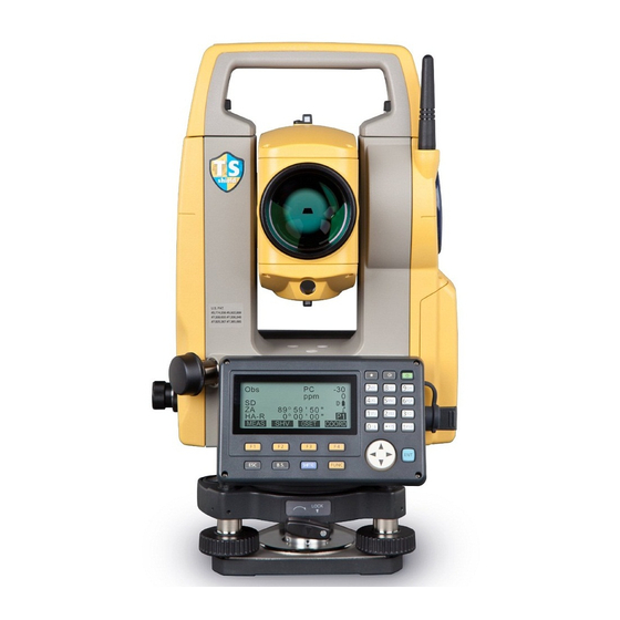
4.1 Parts of the Instrument Identification
Detailed identification and description of all external parts of the ES series instrument.
Operation Panel and Guide Light Functions
Explains the layout and functions of the operation panel keys and the guide light system.
Guide Light Status and Handle Removal
Describes guide light status indicators and the procedure for removing the instrument handle.
4.2 Mode Diagram and Navigation
Illustrates the instrument's mode structure and navigation flow between different modes.
4.3 Bluetooth Wireless Technology
Details Bluetooth function availability, regulations, and potential radio interference issues.
5. Basic Operation
5.1 Basic Key Operation Fundamentals
Covers fundamental key operations, including power control, backlight adjustment, and target/laser pointer switching.
Softkey and Data Input Methods
Explains the use of softkeys and methods for inputting alphanumeric characters and figures.
Option Selection and Mode Switching
Guides on selecting options from lists and switching between different operating modes.
5.2 Display Functions Overview
Describes the information presented on the instrument's various display screens.
5.3 Star Key Mode Operations
Explains how to access and utilize the Star Key menu for common measurement settings.
6. Using the Battery
6.1 Battery Charging Procedures
Details the battery charging process, including temperature ranges and operational characteristics.
6.2 Battery Installation and Removal
Provides instructions for safely installing and removing the battery, maintaining instrument waterproofing.
7. Setting Up the Instrument
7.1 Centering with Optical Plummet
Explains the procedure for accurately centering the instrument over a survey point using the optical plummet.
Centering with Laser Plummet
Guides on using the laser plummet for precise centering of the instrument over a survey point.
7.2 Instrument Levelling Procedure
Details the process of leveling the instrument using tripod legs and leveling foot screws for stability.
8. Focussing and Target Sighting
Telescope Focusing and Target Alignment
Step-by-step guide for focusing the telescope and aligning the target using clamps and fine motion screws.
Eliminating Parallax for Accuracy
Explains how to identify and remove parallax to ensure accurate readings and avoid errors.
9. Power On/Off
Instrument Power On Procedure
Covers powering on the instrument, self-checks, password entry, and entering OBS mode.
Instrument Power Off Procedure
Details powering off the instrument, including battery status indicators and auto power-off settings.
10. Connecting to External Devices
Bluetooth Communication Setup Requirements
Outlines necessary settings for Bluetooth communication, including master/slave modes and initial configurations.
Setting Bluetooth Communication to Master Mode
Guides on setting the instrument to Master mode for Bluetooth connection, including companion device registration.
10.2 Establishing Bluetooth Connection
Explains establishing a Bluetooth connection between the ES and a paired device, noting battery usage.
Bluetooth Communication Procedures (Slave Mode)
Covers procedures for Bluetooth communication when the ES is set to Slave mode.
Bluetooth Communication Procedures (Master Mode)
Details procedures for Bluetooth communication when the ES is set to Master mode.
10.3 Performing Measurement via Bluetooth
Explains how to initiate measurements using a data collector connected via Bluetooth.
10.4 Registering/Outputting Data via Bluetooth
Covers registering known point data and outputting JOB data wirelessly using Bluetooth.
10.5 Connecting via Communication Cable
Outlines the procedure for basic cable connection settings between the ES and an external device.
11. Angle Measurement
11.1 Measuring Horizontal Angle Between Two Points
Explains using the 0SET function to measure the included horizontal angle between two points.
11.2 Setting Horizontal Angle to Required Value
Guides on resetting the horizontal angle or holding a specific angle value.
11.3 Angle Measurement and Data Output
Details angle measurement and outputting the data to computers or peripheral equipment.
12. Distance Measurement
12.1 Returned Signal Checking Procedure
Explains checking returned signal strength for accurate distance measurements, especially for long distances.
12.2 Distance and Angle Measurement
Describes how to perform simultaneous distance and angle measurements to a target.
12.3 Recalling Measured Data
Explains how to access and display previously measured distance and angle data.
12.4 Distance Measurement and Data Output
Details the process of measuring distances and outputting the data to external devices.
12.5 Coordinate Measurement and Data Output
Covers measuring coordinates and outputting the data to external devices.
12.6 REM Measurement Procedure
Explains the REM measurement function for determining the height of inaccessible points.
13. Setting Instrument Station
Instrument Station Data and Backsight Angle Setup
Covers setting instrument station data and backsight angle using various methods.
13.1 Entering Station Data and Azimuth Angle
Details inputting instrument station coordinates, heights, and azimuth angle before measurements.
Reading Registered Coordinate Data
Guides on loading and using previously stored coordinate data for setup.
Coordinate Data Search (Complete Match)
Explains searching for coordinate data using an exact match criteria.
Coordinate Data Search (Partial Match)
Describes searching for coordinate data using a partial match criteria.
13.1.1 Setting Azimuth Angle from Coordinates
Details calculating azimuth angle from backsight station coordinates.
13.2 Setting Station Coordinates via Resection
Explains determining instrument station coordinates using resection measurement by observing known points.
13.2.1 Observation Settings for Resection
Covers observation setup for resection, including RL observation and sigma Z display.
13.2.2 Coordinate Resection Measurement
Guides on measuring known points to calculate instrument station coordinates via coordinate resection.
13.2.3 RL Observation in Resection
Details performing RL observations during resection for both faces.
13.2.4 Height Resection Measurement
Explains determining instrument station height (Z coordinate) using height resection.
14. Coordinate Measurement
3-D Coordinate Measurement Procedure
Describes measuring target coordinates using instrument and backsight station data.
Coordinate Measurement Procedure
Outlines steps for measuring target coordinates by sighting and setting observation parameters.
15. Setting-out Measurement
15.1 Coordinates Setting-out Measurement
Explains setting out points by inputting coordinates and calculating required angles and distances.
15.2 Distance Setting-out Measurement
Details setting out points based on horizontal angle and distance from the instrument.
15.3 REM Setting-out Measurement
Explains REM setting-out for points inaccessible for direct measurement.
16. Setting-out Line
16.1 Defining Baseline for Line Setup
Covers defining a baseline by inputting or observing two points for setting-out line operations.
Defining Baseline by Observation
Guides on defining a baseline by observing points, including instrument station data entry.
16.2 Setting-out Line Point Calculation
Explains calculating required point coordinates by inputting length and offset relative to a baseline.
16.3 Setting-out Line Alignment Measurement
Describes measuring horizontal and vertical distances of a point from a connected line or baseline.
17. Setting-out Arc
17.1 Defining an Arc by Inputting Coordinates
Details defining an arc by entering parameters like radius, angle, and point coordinates.
Defining Arc by Observation
Guides on defining an arc through observation, including instrument station data and point selection.
17.2 Setting-out Arc Calculation
Explains finding required point coordinates along an arc using input arc length, offset, and curve properties.
18. Point Projection
18.1 Defining Baseline for Point Projection
Covers defining a baseline for projecting points, noting its reusability in other functions.
18.2 Point Projection Procedure
Guides on entering point coordinates to project them onto a baseline and calculate distances.
19. Topography Observation
Topography Observation Order
Illustrates the observation sequence for standard and RL topography measurements.
Topography RL Observation Order
Shows the specific observation sequence for topography RL measurements.
19.1 Observation Setting for Topography
Details setting observation parameters for topography, including measurement patterns and backsight settings.
19.2 Topography Observation Procedure
Guides on performing topography observations, measuring directions, and recording data.
Topography RL Observation Procedure
Details conducting RL topography observations by measuring target points in R and L directions.
20. Offset Measurement
20.1 Single-distance Offset Measurement
Explains measuring distance and angle to an offset point when direct sighting is difficult.
20.2 Angle Offset Measurement
Details finding a target's position from an included angle by measuring to offset points.
20.3 Two-distance Offset Measurement
Explains measuring distances to two offset points to find the target point, possibly using a 2-point target.
20.4 Plane Offset Measurement
Describes measuring distance and coordinate of a plane edge by observing three random points.
20.5 Column Offset Measurement
Explains finding column center coordinates and azimuth by measuring circumscription points.
21. Missing Line Measurement
21.1 Measuring Distance Between Multiple Points
Guides on measuring distances and angles to targets from a starting point without instrument movement.
Calculating Missing Line from Input Coordinates
Explains calculating missing line measurements by inputting coordinates for targets.
21.2 Changing the Starting Point
Describes how to change the last measured point to the next starting position for missing line measurements.
22. Surface Area Calculation
Surface Area Calculation by Observing Points
Details calculating area by observing points on a boundary line in sequence.
Surface Area Calculation from Coordinates
Explains calculating area by loading and processing previously registered coordinate data.
23. Intersections
Finding Intersection Points Procedure
Outlines the process to find intersection points between reference points by specifying length or azimuth.
Defining Two Intersections
Explains how two intersections are defined based on input azimuth and distance values.
Intersection Measurement Precautions
Lists conditions that prevent calculation of intersection points.
24. Traverse Adjustment
Traverse Calculation Procedure
Describes the initial steps for traverse calculation, including observation sequence and recording.
Adjustment Options and Methods
Explains adjustment options like Compass, Transit, and distribution methods for angles and elevations.
Traverse Adjustment Methods Explained
Details the mathematical methods for adjusting traverse data, including coordinate and angular adjustments.
Types of Traverse Calculation
Lists calculable traverse types and requirements for start/end point azimuths.
Automatic Route Search Function
Describes the automatic route search feature for identifying potential traverse routes from stored points.
25. Route Surveying
Route Surveying Symbols and Terms
Defines key symbols and terms used in route surveying operations.
25.1 Instrument Station Settings
Covers setting the instrument station as a reference point for route surveying.
25.2 Straight Line Calculation
Explains calculating coordinates for center and width pegs of a straight line.
25.3 Circular Curve Calculation
Details calculating center and width peg coordinates for circular curves.
25.4 Spiral Curve Calculation
Explains calculating center and width pegs for spiral curves using reference points.
Spiral Curve Calculation Methods
Describes different methods for calculating spiral curves based on reference points.
25.7 Intersection Angle/Azimuth Angle Calculation
Covers calculating cardinal points and pegs from intersection angles and curve properties.
25.5 Parabola Calculation
Explains finding center and width pegs for parabola curves using reference points.
Parabola Calculation Methods
Details calculation methods for parabolas, including using BTC and ECC points as references.
25.6 3 Point Calculation
Guides on finding cardinal points, pegs from 3 IP points and curve properties.
25.7 Intersection Angle/Azimuth Angle Calculation
Explains calculating cardinal points, pegs from intersection angles and curve properties.
25.8 Route Calculation Overview
Covers calculating center and width pegs for a route with multiple curves, including cardinal point calculations.
25.8.1 Inputting IPs for Route Calculation
Details the process of inputting Intersection Points (IPs) for route calculation.
25.8.3 Displaying Curve Properties
Explains how to check and modify curve properties previously entered.
25.8.4 Clearing Route Data
Guides on clearing route data, including IPs and curve elements.
25.8.5 Automatic Cardinal Point Calculation
Explains automatic calculation of cardinal points based on curve properties.
25.8.7 Inverse Width Peg Calculation
Details finding route widths and coordinates for center pegs using inverse width peg calculation.
25.8.8 Setting Parameters for Route Calculation
Covers setting parameters for curve calculation, including preset types and BP point settings.
26. Cross Section Survey
Cross Section Survey Purpose and Terminology
Explains the function of cross-section surveying and defines related terms.
Initiating a Cross Section Survey
Outlines the initial steps to start a cross-section survey, including selecting the survey type and entering station data.
Cross-Section Observation Directions
Describes different observation patterns (Left, Right) for cross-section surveys based on the selected direction.
Reviewing Cross Section Survey Data
Explains how to review cross-section data stored in a JOB, including the meaning of "Offset".
27. Point to Line Measurement
Setting Baseline for Point to Line Measurement
Guides on setting a baseline connecting two points to define a line for measuring target points.
Point to Line Measurement Procedure
Details measuring target points relative to a defined line, including instrument station coordinates.
28. Recording Data - TOPO Menu
28.1 Recording Instrument Station Data
Explains storing instrument station coordinates, name, height, and other related data.
28.2 Recording Backsight Point Data
Covers recording backsight station data, including target height, point name, code, and azimuth angle.
Calculating Azimuth Angle from Coordinates
Describes calculating the azimuth angle using backsight station coordinates.
28.3 Recording Angle Measurement Data
Details storing angle measurement data, including target height, point name, and code.
28.4 Recording Distance Measurement Data
Explains storing distance measurement data, including target height, point name, and code.
28.5 Recording Coordinate Data
Covers storing coordinate measurement data, including target height, point name, and code.
28.6 Recording Distance and Coordinate Data
Describes storing both distance and coordinate data simultaneously with the same point name.
28.7 Recording Notes
Explains preparing and recording notes data in the current JOB.
28.8 Reviewing JOB Data
Guides on displaying and searching through data stored in the current JOB.
28.9 Deleting Recorded JOB Data
Explains how to delete specific data items or clear all data from a JOB.
29. Selecting/Deleting a JOB
29.1 Selecting a JOB
Covers selecting the current JOB and Coordinate Search JOB, including scale factor settings.
Inputting a JOB Name and Scale Factor
Details changing a JOB name and setting the scale factor for the current JOB.
29.2 Deleting a JOB
Explains how to delete a JOB and notes on data that cannot be deleted.
30. Registering/Deleting Data
30.1 Registering/Deleting Known Point Data
Covers registering or deleting coordinate data for known points via key entry or external input.
Deleting Designated Coordinate Data
Guides on selecting and deleting specific known point coordinate data.
30.2 Reviewing Known Point Data
Explains how to display all coordinate data within the current JOB.
30.3 Registering/Deleting Codes
Details saving and deleting codes for data recording.
Entering Codes from External Instrument
Describes entering codes from an external device via communication setup.
Deleting Codes
Guides on deleting registered codes from the instrument.
30.4 Reviewing Codes
Explains how to view the list of registered codes.
31. Outputting JOB Data
31.1 Outputting JOB Data to Host Computer
Details the process of outputting JOB data (measurements, station data, notes) to a host computer.
Code Output to Host Computer
Explains how to output code data to a host computer, requiring specific communication settings.
32. Using USB Memory Device
32.1 Inserting the USB Memory Device
Provides instructions on how to properly insert and remove a USB memory device.
32.2 Selecting T type/S type for USB
Explains selecting communication formats (T type/S type) for USB data transfer.
32.3 Storing JOB Data to USB Device
Details saving JOB data, including measurements and notes, to a USB memory device.
Saving Code Data to USB Memory
Guides on saving code data to a USB device, requiring specific communication settings.
32.4 Loading Data from USB Device to ES
Explains loading known point data or code from USB to the current JOB.
32.5 Displaying and Editing Files on USB
Covers displaying file information, editing names, and deleting files on the USB device.
Editing File Names on USB
Details the process of editing file names on the USB memory device.
32.6 Formatting USB Memory Media
Explains how to format the USB memory device using the quick format option.
33. Changing the Settings
33.1 Configuration Mode Settings
Explains parameter settings within Config Mode, covering observation conditions.
Observation Condition Settings Details
Details settings for distance mode, tilt compensation, collimation, and sea level correction.
Horizontal Distance Display Methods
Describes the Ground and Grid methods for displaying horizontal distance.
Automatic Tilt Angle Compensation Mechanism
Explains the automatic tilt compensation using the 2-axis tilt sensor.
Collimation and Sea Level Correction
Details collimation correction for angle errors and sea level correction for horizontal distance.
Vertical Angle, Sheet Mode, and Input Order Settings
Covers vertical angle display, target selection in Sheet mode, and input order for data.
Instrument Configuration Settings
Details settings for power-off, contrast, resume function, and guide pattern.
Power Saving and Resume Functions
Explains automatic power cut-off and the resume function for screen display.
EDM ALC Settings for Measurement
Details setting the light receiving status of the EDM for continuous measurement.
Communication Setup Parameters
Covers communication settings like wireless, baud rate, data bits, and protocols.
33.4 Changing Password
Explains how to change the instrument's password.
33.5 Restoring Default Settings
Describes methods to restore default settings, including initial setup and data initialization.
Procedure for Changing Password
Details the step-by-step process to change the instrument's password.
Procedures for Restoring Settings
Outlines procedures for restoring settings to initial states via power cycling.
34. Warning and Error Messages
Common Condition and File Name Errors
Lists errors for poor measuring conditions and invalid file names during USB operations.
Calculation, Checksum, and Clock Errors
Explains errors during calculations, data transmission, and clock/battery issues.
Communication and USB Errors
Covers errors related to communication, USB device status, and memory.
Flash Write, Password, and USB Device Errors
Lists errors for flash memory, incorrect passwords, and USB device issues.
Baseline and Memory Full Errors
Covers errors related to invalid baselines and full instrument memory.
Measurement Progress Errors
Lists errors indicating incomplete observations like "Need 1st obs" or "Need 2nd obs".
Password, Data, File, and Solution Errors
Explains errors for password mismatches, missing data, file issues, and calculation failures.
Range and Plane Offset Errors
Discusses errors for out-of-range tilt angles and invalid directions in plane offset measurements.
Value Range and Route Errors
Lists errors for out-of-value conditions, invalid route closing, and file format issues.
Signal, Coordinate, Temperature, and Time Errors
Covers errors for signal issues, null coordinates, temperature range, and timeouts.
Password Length and USB Errors
Details errors related to password length and various USB operations.
35. Checks and Adjustments
35.1 Circular Level Check and Adjustment
Guides on checking and adjusting the circular level for proper instrument centering.
35.2 Tilt Sensor Check Procedure
Explains checking the tilt sensor and canceling tilt zero point errors.
Tilt Sensor Adjustment Procedure
Details the procedure for adjusting the tilt sensor by calculating offset values.
35.3 Collimation Check and Adjustment
Explains measuring and correcting collimation error using angular observations.
35.4 Reticle Perpendicularity Check
Guides on checking reticle perpendicularity to the horizontal axis.
Vertical and Horizontal Reticle Line Check
Details checking vertical and horizontal reticle line positions using face left/right measurements.
35.5 Optical Plummet Check and Adjustment
Explains checking and adjusting the optical plummet for accurate centering.
35.6 Additive Distance Constant Check
Details checking the additive distance constant (K) using a known distance baseline.
35.7 Laser Plummet Check and Adjustment
Guides on checking and adjusting the laser plummet beam alignment.
36. Standard Equipment and Optional Accessories
Standard Equipment List Reference
Refers to a separate sheet for a list of standard components included with the instrument.
Optional Accessories Overview
Lists optional accessories sold separately, including targets and power supplies.
Eyepieces, Solar Filter, and Cables
Describes eyepieces, solar filter, and interface/power cables for data output.
Prism System Configurations
Illustrates prism system arrangements and provides notes on setup and tribrach compatibility.
36.4 Power Supplies and Accessories
Lists compatible power sources like batteries, chargers, and external power options.
External Power Supply Equipment Usage
Provides guidance on using external batteries and car batteries safely and correctly.
37. Specifications
Telescope and Angle Measurement Specs
Details specifications for the telescope and angle measurement system.
Angle Measurement Accuracy and Units
Lists angle measurement accuracy, units, and minimum display values.
Tilt Compensation and Distance Measurement Specs
Covers specifications for tilt compensation, distance measurement methods, and laser source.
Distance Measurement Ranges
Lists measuring ranges for various targets and atmospheric conditions.
Minimum Display and Measurement Accuracy
Details minimum display values and accuracy for measurement modes.
Measurement Modes, Time, and Correction Input
Lists measurement modes, times, and input ranges for atmospheric correction.
Input Ranges and Correction Settings
Lists input ranges for pressure, ppm, prism constant, and earth curvature correction.
Scale Factor, Sea Level, Guide Light, Memory
Covers scale factor, sea level correction, guide light, and internal memory specifications.
External Memory, Data Transfer, and Bluetooth Specs
Details specifications for USB memory, data transfer, and Bluetooth wireless technology.
Power Supply and Battery Specifications
Lists specifications for power sources, batteries, and charging.
Charger and General Unit Specifications
Lists charger specifications and general details for the display unit and operation panel.
Level Sensitivity and Optical Plummet Specs
Details specifications for levels and the optical plummet.
Laser Plummet and Beam Accuracy Specs
Specifies laser plummet source, accuracy, spot diameter, and brightness.
Spot Diameter, Brightness, and Temperature Specs
Details specifications for spot diameter, brightness control, and operating/storage temperatures.
Dust Resistance, Instrument Height, Size, Weight
Provides specifications for dust/water resistance, instrument height, size, and weight.
Measurement Accuracy and Modes Details
Lists accuracy specifications for measurement modes and time.
Atmospheric Correction and Guide Light
Covers input ranges for atmospheric correction and specifications for the guide light.
Laser Plummet Specifications
Specifies laser plummet signal source, beam accuracy, spot diameter, and brightness.
38. Explanation
38.1 Manually Indexing Vertical Circle
Explains the procedure for manually indexing the vertical circle for high-precision measurements.
38.2 Correction for Refraction and Earth Curvature
Details distance calculation corrections for refraction and earth curvature, including formulas.
39. Regulations
USA FCC Compliance and Declarations
Covers FCC compliance, warnings, and conformity declarations for USA.
USA Representative and California Proposition 65
Provides US representative details and California Proposition 65 warnings.
California Perchlorate Material and Battery Recycling
Addresses perchlorate material warnings and battery recycling information.
Canadian and European Compliance
Details Canadian ICES-Class A and European EMC/R&TTE directives.
EU Directives and Asian Regulations
Covers EU directives and regulations for Republic of Korea and Taiwan.
China SRRC and Environmental Directives
Lists China's SRRC regulations and environmental directives.
Need help?
Do you have a question about the ES-103 and is the answer not in the manual?
Questions and answers