Page 1
INSTRUCTION MANUAL EASY STATION ES series ES-101 ES-102 ES-103 ES-105 ES-107 21405 99257...
Page 2
S Li-ion Li-ion :This is the mark of the Japan Surveying Instruments Manufacturers Association.
Page 3
The specifications and general appearance of the instrument are subject to change without prior notice and without obligation by TOPCON CORPORATION and may differ from those appearing in this manual. The content of this manual is subject to change without notice.
Page 4
<S-O> etc. : Indicates screen titles. Notes regarding manual style • Except where stated, “ES” means ES-101/102/103/105/107. • The ES Series is available in "standard" and "Low Temperature" models. Users with a "Low Temperature Model" should read the additional precautions specific to use under low temperatures.
Page 5
• Measurement procedures are based on continuous measurement. Some information about procedures when other measurement options are selected can be found in “Note” ( • indicates functions/options not available on all products. Contact your local dealer for availability with your product. •...
1. PRECAUTIONS FOR SAFE OPERATION For the safe use of the product and prevention of injury to operators and other persons as well as prevention of property damage, items which should be observed are indicated by an exclamation point within a triangle used with WARNING and CAUTION statements in this instruction manual.
Page 12
1. PRECAUTIONS FOR SAFE OPERATION General Warning Do not use the unit in areas exposed to high amounts of dust or ash, in areas where there is inadequate ventilation, or near combustible materials. An explosion could occur. Do not perform disassembly or rebuilding.
Page 13
1. PRECAUTIONS FOR SAFE OPERATION Power Supply Warning Do not place articles such as clothing on the battery charger while charging batteries. Sparks could be induced, leading to fire. Do not use batteries other than those designated. An explosion could occur, or abnormal heat generated, leading to fire.
Page 14
1. PRECAUTIONS FOR SAFE OPERATION Tripod Caution When mounting the instrument to the tripod, tighten the centering screw securely. Failure to tighten the screw properly could result in the instrument falling off the tripod, causing injury. Tighten securely the leg fixing screws of the tripod on which the instrument ...
2. PRECAUTIONS Charging Battery • Be sure to charge the battery within the charging temperature range. Charging temperature range: 0 to 40°C Warranty policy for Battery • Battery is an expendable item. The decline in retained capacity depending on the repeated charging/discharging cycle is out of warranty. Bluetooth Wireless Technology •...
Page 16
2. PRECAUTIONS • Do not press the speaker hole using something with a pointed tip. Doing so will damage an internal waterproof sheet, resulting in a degraded waterproof property. • If there is a crack or deformation in the rubber packing for the battery cover or external interface hatch, stop using and replace the packing.
Page 17
2. PRECAUTIONS • The lens cap and lens hood may become difficult to attach in low temperatures. Keep them in a warm place such as a pocket until attached. • If the unit is carried between locations that have extreme temperature differences, protect the unit from rapid temperature change by placing it in the carrying case.
Page 18
2. PRECAUTIONS Maintenance • Always clean the instrument before returning it to the case. The lens requires special care. First, dust it off with the lens brush to remove tiny particles. Then, after providing a little condensation by breathing on the lens, wipe it with the wiping cloth.
Page 19
2. PRECAUTIONS Exporting this product (Relating telecommunications regulations). • Wireless communication module is incorporated in the instrument. Use of this technology must be compliant with telecommunications regulations of the country where the instrument is being used. Even exporting the wireless communication module may require conformity with the regulations.
3. LASER SAFETY INFORMATION ES is classified as the following class of Laser Product according to IEC Standard Publication 60825-1 Ed.2.0: 2007 and United States Government Code of Federal Regulation FDA CDRH 21CFR Part 1040.10 and 1040.11 (Complies with FDA performance standards for laser products except for deviations pursuant to Laser Notice No.50, dated June 24, 2007.) Device Laser class...
Page 21
3. LASER SAFETY INFORMATION • Never intentionally point the laser beam at another person.The laser beam is injurious to the eyes and skin. If an eye injury is caused by exposure to the laser beam, seek immediate medical attention from a licensed ophthalmologist. •...
18 Tubular compass slot 19 Vertical clamp 20 Vertical fine motion screw 21 Speaker 22 Trigger key 23 Horizontal fine motion screw ES-101/102 and Low Temperature 24 Horizontal clamp Models only 25 Tribrach clamp 26 Telescope eyepiece screw 27 Telescope focussing ring...
Page 23
4. ES FUNCTIONS Sighting collimator Use sighting collimator to aim the ES in the direction of the measurement point. Turn the instrument until the triangle in the sighting collimator is aligned with the target. Instrument height mark The height of the ES is as follows: •...
Page 24
4. ES FUNCTIONS Operation panel "5.1 Basic Key Operation" Illumination key Star key Power key Display unit Softkey selection Guide light Guide light Guide light Setting-out measurement etc. can be carried out effectively using the Guide light. The Guide light is composed of a light that is divided into a red and a green light.
Page 25
4. ES FUNCTIONS Guide light status Light status Meaning (From position of poleman) Move target left Green (From position of poleman) Move target right Red and Green Target is at correct horizontal position When the guide light is turned ON, it is displayed as a symbol in the display unit.
4. ES FUNCTIONS Mode Diagram Star key Mode L - p o i n t e r O f f Dist+Coord Note R e f l e c t o r P r i s m View L a s e r p l u m : O f f Deletion L a s e r l e v.
"39. REGULATIONS" • TOPCON CORPORATION is not liable for the content of any transmission nor any content related thereto. When communicating important data, run tests beforehand to ascertain that communication is operating normally. • Do not divulge the content of any transmission to any third party.
Page 28
Similarly, usable range may also shorten when performing communication in wooded areas. Moreover, as wireless devices lose signal strength when close to the ground, perform communication at as high a position as possible. • TOPCON CORPORATION cannot guarantee full compatibility with all Bluetooth products on the market.
5. BASIC OPERATION Basic Key Operation Learn basic key operations here before you read each measurement procedure. Location of operation keys on the panel : "4.1 
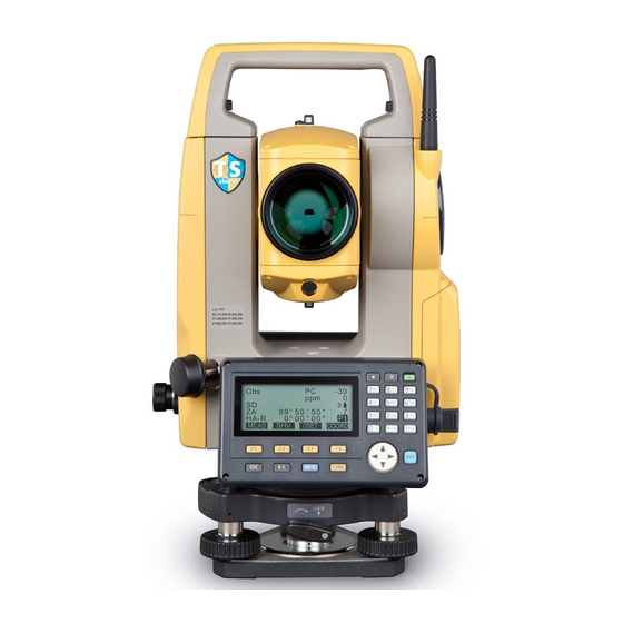
Parts of the Instrument" Power ON / OFF {ON} Power On {ON} Power Off (Press and hold: About 1 second)
Page 30
5. BASIC OPERATION Softkey operation Softkeys are displayed on the bottom line of the screen. {F1} to {F4} Select the function matching the softkeys {FUNC} Toggle between OBS mode screen pages (when more than 4 softkeys are allocated) Inputting letters/figures ...
Page 31
5. BASIC OPERATION 6. Press {5} once. JOB details "M" is displayed. Press {ENT } to JOB name complete inputting. JOB M SCALE: 1.00000000 Selecting options Up and down cursor {}/{} Right and left cursor/Select other option {ENT} Accept the option Example: Select a reflector type...
5. BASIC OPERATION Display Functions Status screen Instrument name ES-103 rec 9999 S/N 123456 Application Ver. XXX-XX-XX software XXX-XX-XX version Job.JOB1 DATA CNFG OBS mode screen Target *5 Prism constant value Atmospheric correction factor Distance *1 Remaining battery power *4 Vertical angle *2 Tilt angle compensation *6 HA-R...
Page 33
5. BASIC OPERATION * 2 Vertical angle Switching vertical angle display status: "33.1 Configuration -Config Mode-" ZA : Zenith angle (Z=0) VA : Vertical angle (H=0/H=±90) To switch vertical angle/slope in %, press [ZA/%] * 3 Horizontal angle Press [R/L] to switch the display status. HA-R: Horizontal angle right HA-L: Horizontal angle left * 1,2,3...
Page 34
5. BASIC OPERATION *7 Laser-pointer/Guide light display Selecting Laser-pointer/Guide light: "33.2 EDM Settings", Switching Laser-pointer/Guide light ON/OFF : "5.1 Basic Key Operation" :Laser-pointer is selected and ON :Guide light is selected and ON *8 Bluetooth communication status : Connection established (“Mode” is set to “Slave”) : Connection established (“Mode”...
5. BASIC OPERATION Star Key Mode Pressing the Star key { } displays the Star Key menu. In the Star Key mode, you can start the measurement program from the Entry menu and change the setting commonly used for measuring. E n t r y m e n u R e f l e c t o r P r i s m...
6. USING THE BATTERY Battery Charging The battery has not been charged at the factory. • The charger will become rather hot during use. This is normal. • Do not use to charge batteries other than those specified. • The charger is for indoor use only. Do not use outdoors. •...
Page 37
6. USING THE BATTERY PROCEDURE 1. Connect the power cable to the charger and plug the charger into the wall outlet. 2. Mount the battery in the charger by matching the grooves on the battery with the guides on the charger.
6. USING THE BATTERY Installing/Removing the Battery Mount the charged battery. • Use the provided battery BDC70 for this instrument. • When removing the battery, turn the power off. • When installing/removing the battery, make sure that moisture or dust particles do not come in contact with the inside of the instrument.
7. SETTING UP THE INSTRUMENT • Mount the battery in the instrument before performing this operation because the instrument will tilt slightly if the battery is mounted after levelling. Centering PROCEDURE Centering with the optical plummet eyepiece 1. Make sure the legs are spaced at equal intervals and the head is approximately level.
Page 40
7. SETTING UP THE INSTRUMENT 4. Adjust the levelling foot screws to center the survey point in the optical plummet reticle. 5. Continue to the levelling procedure. "7.2 Levelling" PROCEDURE Centering with the laser plummet ( 1. Set up the tripod and affix the instrument on the tripod head.
7. SETTING UP THE INSTRUMENT 6. Press [L-OFF] to turn the laser plummet off. Alternatively, press {ESC} to return to the previous screen. The laser plummet will switch off automatically. 7. Continue to the levelling procedure. "7.2 Levelling" •...
Page 42
7. SETTING UP THE INSTRUMENT 3. Press {ON} to power on "9. POWER ON/OFF" • The circular level is displayed on the screen. • “” indicates bubble in circular level. The range of the inside circle is ±4' and the range of the outside circle is ±6'.
Page 43
7. SETTING UP THE INSTRUMENT 6. Set the tilt angle to 0° using foot screws A and B for the X direction and levelling screw C for the Y direction. 7. Loosen the centering screw slightly. Looking through the optical plummet eyepiece, slide the instrument over the tripod head until the survey point is exactly...
8. FOCUSSING AND TARGET SIGHTING • When sighting the target, strong light shining directly into the objective lens may cause the instrument to malfunction. Protect the objective lens from direct light by attaching the lens hood. Observe to the same point of the reticle when the telescope face is changed. PROCEDURE 1.
Page 45
8. FOCUSSING AND TARGET SIGHTING 4. Readjust the focus with the focussing ring until there is no parallax between the target image and the reticle. Eliminating parallax This is the relative displacement of the target image with respect to the reticle when the observer’s head is moved slightly before the eyepiece.
9. POWER ON/OFF Setting “V manual”: "33.1 Configuration -Config Mode-", Setting/changing password: "33.4 Changing Password" PROCEDURE Power ON 1. Press {ON}. When the power is switched on, a self-check is run to make sure the instrument is operating normally. •...
Page 47
9. POWER ON/OFF • When “Resume” in “Instr. config” is set to “On”, the screen previous to power off is displayed (except when missing line measurement was being performed). "33.1 Configuration -Config Mode-" PROCEDURE Power OFF 1. Long push {ON} button. ...
10. CONNECTING TO EXTERNAL DEVICES The ES supports Bluetooth wireless technology and RS232C for communication with data collectors etc. 10.1 Necessary settings for Bluetooth communication The Bluetooth module incorporated in the ES can be used for communication with Bluetooth devices such as data collectors. ...
Page 49
10. CONNECTING TO EXTERNAL DEVICES Select "Bluetooth setup" and Wireless check that "Mode" is set to "Slave". Bluetooth setup Link device list My device info • Only "Slave" can be selected when the ES is shipped. Slave Mode Authentication : No Check sum : No 3.
10. CONNECTING TO EXTERNAL DEVICES • No changes for the setting' A C K / N A K C R , L F : N o "Mode", "Authentication" and A C K m o d e : S t a n d a r d "Check sum"...
Page 51
10. CONNECTING TO EXTERNAL DEVICES 2. Select "Comms setup" in Config mode. 3. Set "Wireless" to "Yes". 4. Select "Link device list". Wireless Bluetooth device list is displayed. Bluetooth setup (Default device names are Link device list My device info displayed when ES was shipped).
Page 52
10. CONNECTING TO EXTERNAL DEVICES • When registering a device manually, input the Bluetooth address in 12 hexadecimal digits. (":" is unnecessary). 7. Press [REG] to complete the Device registration registration. Name: DEVICE1 BD_ADDR: 0123456789AB SEARCH 8. Set "Mode" to "Master". Master Mode DEVICE1...
10. CONNECTING TO EXTERNAL DEVICES PROCEDURE Displaying Bluetooth information for the ES 1. Select "Comms setup" in Config mode. 2. Set "Wireless" to "Yes". 3. Select "My device info". Wireless The Bluetooth information for the Bluetooth setup ES is displayed. The "BD ADDR" Link device list My device info for the ES must be registered on...
Page 54
10. CONNECTING TO EXTERNAL DEVICES When "Wireless" is set to "Yes" in "Comms setup" in Config mode [ ] is displayed in OBS mode. • Softkeys (in OBS mode) Softkey Connection mode Operation Slave Enter waiting status Master Establish a connection Slave Cancel the connection/exit waiting status Master...
Page 55
10. CONNECTING TO EXTERNAL DEVICES 2. Chek that the ES is in waiting status (Bluetooth symbol is (flashing)) and start communication by the data HA-R collector. Manual of the program mounted on the data collector The Bluetooth icon: "5.2 Display Functions"...
10. CONNECTING TO EXTERNAL DEVICES 2. Returning to Obs Mode, the ES starts searching the device selected in "Link" and establishes a connection. When connection HA-R has been established, Bluetooth symbol turns (lit). The Bluetooth icon: "5.2 Display Functions" HA-R 3.
10. CONNECTING TO EXTERNAL DEVICES 10.4 Registering/Outputting data using Bluetooth communication It is possible to set a computer as the companion device and register known point data or output JOB data via wireless communication. PROCEDURE Entering known point coordinate data from an external instrument 1.
Page 58
10. CONNECTING TO EXTERNAL DEVICES PROCEDURE Outputting JOB data to a host computer 1. Complete the necessary settings for Bluetooth communication. "10.1 Necessary settings for Bluetooth communication" 2. Verify the current connection status by checking the Bluetooth icon in the OBS mode screen. ...
10. CONNECTING TO EXTERNAL DEVICES 10.5 Connecting via Communication Cable PROCEDURE Basic cable settings 1. Connect the ES to the external device using the cable. Cables: "36.2 Optional accessories" 2. Select “Comms setup” in Config mode. Set communication conditions. ...
11. ANGLE MEASUREMENT This section explains the procedures for basic angle measurement. 11.1 Measuring the Horizontal Angle between Two Points (Horizontal Angle 0°) Use the “0SET” function to measure the included angle between two points. The horizontal angle can be set to 0 at any direction. PROCEDURE 1.
11. ANGLE MEASUREMENT 11.2 Setting the Horizontal Angle to a Required Value (Horizontal Angle Hold) You can reset the horizontal angle to a required value and use this value to find the horizontal angle of a new target. PROCEDURE Entering the horizontal angle 1.
Page 62
11. ANGLE MEASUREMENT PROCEDURE Entering the coordinate 1. Press [H-SET] on the second Set H angle page of the OBS mode and select Angle "Coord." Coord 2. Set the known point coordinate. S E T H a n g l e / B S Enter the coordinate for the first N B S : 1 0 0 .
11. ANGLE MEASUREMENT 11.3 Angle Measurement and Outputting the Data The following explains angle measurement and the features used to output measurement data to a computer or peripheral equipment. Bluetooth communication: "10. CONNECTING TO EXTERNAL DEVICES" Communication cables: "36.2 Optional accessories" Output format and command operations: "Communication manual"...
12. DISTANCE MEASUREMENT 12.1 Returned Signal Checking • Check to make sure that sufficient reflected light is returned by the reflective prism sighted by the telescope. Checking the returned signal is particularly useful when performing long distance measurements. • When the light intensity is sufficient even though the center of the reflective prism and the reticle are slightly misaligned (short distance etc.), “*”...
12. DISTANCE MEASUREMENT 4. Press {ESC} to finish signal checking and return to Obs Mode. • When is displayed persistently, contact your local dealer. • If no key operations are performed for two minutes, the display automatically returns to the OBS mode screen. 12.2 Distance and Angle Measurement An angle can be measured at the same time as the distance.
12. DISTANCE MEASUREMENT 3. Press [STOP] to quit distance measurement. • Each time [SHV] is pressed, SD (Slope distance), HD (Horizontal distance) and VD (Height difference) are displayed alternately. MEAS 0SET COORD • If the single measurement mode is selected, measurement automatically stops after a single measurement.
12. DISTANCE MEASUREMENT 2. Press [CALL]. The stored data that is most recently measured is displayed. • If you have pressed [SHV] beforehand, the distance values are converted into the horizontal distance, elevation difference, and the slope distance and recalled. 3.
12. DISTANCE MEASUREMENT 4. Press [HVDOUT-T] or [HVDOUT- S] to measure the distance and output the data to peripheral equipment. 5. Press [STOP] to stop outputting data and return to Obs Mode. 12.5 Coordinate Measurement and Outputting the Data The following explains coordinate measurement and the features used to output measurement data to a computer or peripheral equipment.
Page 70
12. DISTANCE MEASUREMENT 4. Press [NEZOUT-T] or [NEZOUT- S] to measure the distance and output the data to peripheral equipment. • When the Distance Measurement mode is set to "Tracking" in the EDM Settings, the measured data cannot be output by pressing [NEZOUT-T]. 5.
12. DISTANCE MEASUREMENT 12.6 REM Measurement An REM measurement is a function used to measure the height to a point where a target cannot be directly installed such as power lines, overhead cables and bridges, etc. The height of the target is calculated using the following formula. Ht = h1 + h2 h2 = S sin θ...
Page 72
12. DISTANCE MEASUREMENT The measured distance data (SD), vertical angle (ZA), and horizontal angle (HA-R) are displayed. Press [STOP] to stop the measurement. 3. In the second page of OBS mode screen, press [MENU], then select Area calc. "REM". S-O Line S-O Arc P-Project PT to line...
Page 73
12. DISTANCE MEASUREMENT • Press [HT] to enter an Height instrument height (HI) and a 0.000m target height (HR). 0.000m • When [REC] is pressed, REM data is saved. "28. RECORDING DATA - TOPO MENU -" • Press [HT/Z] on the second page of the REM measurement to display the Z coordinate for the height from the ground to the...
13. SETTING INSTRUMENT STATION It is possible to set from the instrument station data to the backsight angle in a series of procedures. Setting Instrument Station Data • Key input "13.1 Entering Instrument Station Data and Azimuth Angle" Step 3 •...
13. SETTING INSTRUMENT STATION 13.1 Entering Instrument Station Data and Azimuth Angle Before coordinate measurement, enter instrument station coordinates, the instrument height, target height, and azimuth angle. PROCEDURE 1. First measure the target height and instrument height with a tape measure, etc.
Page 76
13. SETTING INSTRUMENT STATION • Press [RESEC] to measure instrument station coordinates by resection measurement. "13.2 Setting Instrument Station Coordinate with resection measurement" 4. Press [BS AZ] in the screen of step 3 to proceed to azimuth angle input. •...
Page 77
13. SETTING INSTRUMENT STATION PROCEDURE Reading in Registered Coordinate Data Known point data, coordinate data and instrument station data in the current JOB and Coordinate Search JOB can be read in. Confirm that the correct JOB containing the coordinates you want to read in is already selected in Coordinate Search JOB in Data Mode.
Page 78
13. SETTING INSTRUMENT STATION • You can edit the coordinate data that was read in. Editing does not affect the original coordinate data. After editing, the point name is no longer displayed. • The point name that was read in is displayed until the current JOB is changed. •...
Page 79
13. SETTING INSTRUMENT STATION PROCEDURE Coordinate Data Search (Partial match) 1. Press [Search] in the registered coordinate data list screen. All coordinate data that includes characters and numbers entered in step 2 is displayed. 2. Enter search criteria. 1 0 0 Enter the following items.
Page 80
13. SETTING INSTRUMENT STATION 2. Press [BS NEZ] after entering the Backsight instrument station data to enter a 100.000 NBS: backsight point coordinate. 100.000 EBS: <Null> ZBS: • When you wish to read in the LOAD registered coordinate data, press [LOAD]. ""13.1 Entering Instrument Station Data and Azimuth Angle"...
Page 81
13. SETTING INSTRUMENT STATION • Press [REC] to record the following data. Instrument station data, backsight station data, known point data, and angle measurement data (distance measurement data when [MEAS] is pressed) • When storing the azimuth angle in the current JOB, press [REC]. ...
13. SETTING INSTRUMENT STATION 13.2 Setting Instrument Station Coordinate with resection measurement Resection is used to determine the coordinates of an instrument station by performing multiple measurements of points whose coordinate values are known. Registered coordinate data can be recalled and set as known point data. Residual of each point can be checked, if necessary.
Page 84
13. SETTING INSTRUMENT STATION • Press [σNEZ] to display standard deviation which describes the measurement accuracy. Press 9 . 9 9 9 [NEZ] to return to the instrument station coordinate screen. RESULT N E Z 0 . 0 0 1 4 m 0 .
Page 85
13. SETTING INSTRUMENT STATION 13.2.2 Coordinate Resection Measurement Observe existing points with known coordinate data to calculate the coordinate value for the instrument station. • Between 2 and 10 known points can be measured by distance measurement, and between 3 and 10 known points by angle measurement. PROCEDURE 1.
Page 86
13. SETTING INSTRUMENT STATION 6. Input coordinates for the first 1 s t P T known point and press [NEXT] to 2 0 . 0 0 0 move to the second point. 3 0 . 0 0 0 4 0 . 0 0 0 1 0 .
Page 87
13. SETTING INSTRUMENT STATION 10. If there are problems with the results of a point, align the cursor - 0 . 0 0 1 0 . 0 0 1 1 s t with that point and press [OMIT]. 0 . 0 0 5 0 .
Page 88
13. SETTING INSTRUMENT STATION • Pressing [REC] displays the backsight point recording screen. Press [OK] to the HA-R 1 2 0 1.400m following data. Instrument station data, backsight station data, known point data, and angle measurement data (distance measurement data when [MEAS] is pressed) Pressing [NO] returns to the 100.001...
Page 89
13. SETTING INSTRUMENT STATION 3. Select "NEZ". Resection. Elevation Setting 4. Measure the first known point in Face Resection 1st R "R" is displayed in the screen title. Press [MEAS] to start measuring. The HA-R 1 2 0 measurement results are displayed on ANGLE MEAS the screen.
Page 90
13. SETTING INSTRUMENT STATION 8. Input coordinates for the first known 1st PT point and press [NEXT] to move to the 2 0 . 0 0 0 second point. 3 0 . 0 0 0 4 0 . 0 0 0 •...
Page 91
13. SETTING INSTRUMENT STATION 13.2.4 Height Resection Measurement Only Z (height) of an instrument station is determined by the measurement. • Known points must be measured by distance measurement only. • Between 1 and 10 known points can be measured. PROCEDURE 1.
Page 92
13. SETTING INSTRUMENT STATION 7. If measuring two or more known points, repeat procedures 4 to 6 in the same way from the second point. • Press {ESC} to return to the previous known point. 8. Press [CALC] to automatically start calculations after observations of all known points are completed.
Page 93
13. SETTING INSTRUMENT STATION Resection calculation process The NE coordinates are found using angle and distance observation equations, and the instrument station coordinates are found using the method of least squares. The Z coordinate is found by treating the average value as the instrument station coordinates.
Page 94
13. SETTING INSTRUMENT STATION It is sometimes impossible to perform a correct calculation in a case such as the one below. When they are on the edge of a single circle, take one of the following measures. (1) Move the instrument station as close as possible to the center of the triangle.
14. COORDINATE MEASUREMENT By performing coordinate measurements it is possible to find the 3-dimensional coordinates of the target based on station point coordinates, instrument height, target height, and azimuth angles of the backsight station which are entered in advance. • EDM setting can be done in coordinate measurement menu. ...
Page 96
14. COORDINATE MEASUREMENT • If not measured or the space is left blank “Null” will be displayed. If station point Z coordinate is set to “Null” the observation result for the Z coordinate is automatically set to “Null”. PROCEDURE 1. Sight the target at the target point. 2.
Page 97
14. COORDINATE MEASUREMENT • The tilt screen is displayed if the instrument is out of level. Level the instrument. "7.2 Levelling" • Enter a target height, point name and code as needed. • [REC]: records measurement 0 . 0 0 0 results •...
15. SETTING-OUT MEASUREMENT Setting-out measurement is used to set out the required point. The difference between the previously input data to the instrument (the setting- out data) and the measured value can be displayed by measuring the horizontal angle, distance or coordinates of the sighted point. The horizontal angle difference and distance difference are calculated and displayed using the following formulae.
15. SETTING-OUT MEASUREMENT 15.1 Coordinates Setting-out Measurement After setting the coordinates for the point to be set out, the ES calculates the setting-out horizontal angle and horizontal distance. By selecting the horizontal angle and then the horizontal distance setting-out functions, the required coordinate location can be set out.
Page 100
15. SETTING-OUT MEASUREMENT 4. Enter the coordinates of the S-O Coord setting-out point. • When [LOAD] is pressed, registered coordinates can be LOAD DISP recalled and used as setting-out coordinates. "13.1 Entering Instrument Station Data and Azimuth Angle PROCEDURE Reading in Registered Coordinate Data"...
Page 101
15. SETTING-OUT MEASUREMENT 8. Move the prism forward and backward until the setting-out Δ distance is 0m. If S-O HD is “+”, move the prism toward yourself, if it is “-”, move the prism away from yourself. • By pressing [← →], an arrow Back pointing to the left or right displays which direction the...
15. SETTING-OUT MEASUREMENT 15.2 Distance Setting-out Measurement The point to be found based on the horizontal angle from the reference direction and the distance from the instrument station. PROCEDURE 1. Press [S-O] in the third page of the OBS mode screen to display <S-O>.
Page 103
15. SETTING-OUT MEASUREMENT • When [LOAD] is pressed, registered coordinates can be recalled and used. Distance and angle are calculated using the coordinate value. "13.1 Entering Instrument Station Data and Azimuth Angle PROCEDURE Reading in Registered Coordinate Data" 5. Set the following items. S-O HD (1) Sdist/Hdist/Vdist: distance from the instrument station to...
Page 104
15. SETTING-OUT MEASUREMENT 8. Press [MEAS] to start distance S-O HD measurement. The target and the distance of the point to be set out Δ is displayed (S-O HD). HA-R DISP MEAS 9. Move the prism to find the point to be set out.
15. SETTING-OUT MEASUREMENT 15.3 REM Setting-out Measurement To find a point where a target cannot be directly installed, perform REM setting- out measurement. "12.6 REM Measurement" PROCEDURE 1. Install a target directly below or directly above the point to be found, then use a measuring tape etc.
Page 106
15. SETTING-OUT MEASUREMENT 7. Press [REM] to begin REM Cutl setting-out measurement. Move the telescope to find the point to be set out. HA-R "15.2 Distance Setting-out MEAS DISP Measurement" steps 9 to 10 : Move the telescope near the ...
16. SETTING-OUT LINE Setting-out line is used for setting out a required point at a designated distance from the baseline and for finding the distance from the baseline to a measured point. 2nd Pt. Fill Grade 1st Pt. Baseline Offset Length Azimuth 16.1 Defining Baseline...
Page 108
16. SETTING-OUT LINE 2. Enter the instrument station data. "13.1 Entering Instrument Station Data and Azimuth Angle" 3. Select “Define baseline” in <Set- Set-out line out line>. Occ.Orien. Define baseline Set-out line 4. Enter the first point data and press D e f i n e 1 s t P T [OK].
Page 109
16. SETTING-OUT LINE 8. Sight the first point and press M e a s u r e 1 s t P T [MEAS]. 1 1 3 . 4 6 4 N p : The measurement results are 9 1 . 0 8 8 ...
Page 110
16. SETTING-OUT LINE 12. Press [OK] on the screen of step S e t - o u t l i n e 11 to define the baseline. <Set-out P o i n t line> is displayed. Move to setting- L i n e line measurement.
Page 111
16. SETTING-OUT LINE 5. Press [OK] to use the 1 1 3 . 4 6 4 N p : measurement results of the first 9 1 . 0 8 8 E p : point. 1 2 . 1 2 2 Z p : HA-R •...
16. SETTING-OUT LINE • Press [1 : **] to change the grade display mode to “1: * * = elevation: horizontal distance”. • It is also possible to perform setting-out line measurement by pressing [S-O LINE] when allocated to the OBS mode screen. ...
Page 113
16. SETTING-OUT LINE (2) Line: Distance along the baseline from the first point to the position at which a line extending from the required point intersects the baseline at right angles (X direction). (3) Offset: Distance from the required point to the position at which a line extending from the required point intersects the baseline at right angles (Y...
Page 114
16. SETTING-OUT LINE PROCEDURE Offsetting the baseline The baseline can be offset in three dimensions using four methods: lengthwise offset, lateral offset, height offset, and rotation angle offset. Lateral offset Rotation angle offset Lengthwise Height offset offset 1. Select “Point” in <Set-out line> S e t - o u t l i n e P o i n t L i n e...
16. SETTING-OUT LINE 4. Press [OK] to return to the screen in step 2. • [MOVE]: Permanently moves the baseline coordinates by the amount set in <Baseline offset>. 5. Press [OK] on the screen of step S e t - o u t l i n e 2.
Page 116
16. SETTING-OUT LINE 2. Enter the offset value. S e t - o u t l i n e • Offset: How much to move the 0 . 0 0 0 O f f s e t baseline. A positive value indicates right MEAS side and a negative value indicates left side.
Page 117
16. SETTING-OUT LINE 5. Sight the next target and press S e t - o u t l i n e [MEAS] to continue the Offline - 0 . 0 0 4 m measurement. 0 . 0 0 6 m Length 1 2 .
17. SETTING-OUT ARC This mode allows the operator to define an arc from various arc parameters, such as From Pt. coordinates, and set out this arc as well as points (offsets) along it. Tangent length Intersection To Pt. Direction Radius Offset Angle From Pt.
Page 119
17. SETTING-OUT ARC 3. Select “Define arc” in <Set-out S e t - o u t a r c arc>. S t n . O r i e n . D e f i n e a r c S e t - o u t a r c •...
Page 120
17. SETTING-OUT ARC • When entering multiple coordinates, [NEXT] is displayed instead of [OK]. Press [NEXT] to input data for the next point. 8. Enter other arc parameters. D i r e c t i o n : L e f t (1) Direction (whether the arc R a d i u s : <...
Page 121
17. SETTING-OUT ARC 10. Press [OK] on the screen of step 9 to define the arc. <Set-out arc> is displayed. Move to setting-out arc measurement. "17.2 Setting-out Arc" step 2 • It is also possible to perform setting-out arc measurement by pressing [S-O ARC] when allocated to the OBS mode screen.
Page 122
17. SETTING-OUT ARC 5. Press [OK] to use the N p : 1 1 3 . 4 6 4 measurement results of the From 9 1 . 0 8 8 E p : point. 1 2 . 1 2 2 Z p : HA-R •Press [MEAS] to observe the first...
Page 123
17. SETTING-OUT ARC 9. Enter other arc parameters. D i r e c t i o n : L e f t (1) Direction (whether the arc R a d i u s : < N u l l > turns right/left from the From A n g l e <...
Page 124
17. SETTING-OUT ARC Specifying points and curve parameters Parameters that can be entered may be restricted depending on the points spec- ified in step 5/6. Parameters that can be entered are marked with a circle ( ○ ). Those that cannot are marked with a cross ( × ). Radius Angle Chord...
17. SETTING-OUT ARC 17.2 Setting-out Arc Setting-out arc measurement can be used to find the coordinates of required points along the arc by inputting the arc (or chord) length and offset based on the arc. Offset Chord • Before performing setting-out arc, the arc must be defined. PROCEDURE 1.
Page 126
17. SETTING-OUT ARC (3) Offset: Distance from the required point to the position on a curve parallel to the original defined arc. A positive value indicates an offset arc to the right, and a negative value indicates an arc to the left. •...
Page 127
17. SETTING-OUT ARC PROCEDURE Offsetting the arcline The arcline can be offset in three dimensions using four methods: lateral offset, rotation angle offset, lengthwise offset, and height offset. Lateral offset Rotation angle offset Lengthwise Height offset offset 1. Select “Set-out arc” in <Set-out arc>.
Page 128
17. SETTING-OUT ARC 4. Press [OK] to return to the screen in step 2. • [MOVE]: Permanently moves the baseline coordinates by the amount set in <Arcline offset>. 5. Press [OK] on the screen of step S e t - o u t a r c 2.
18. POINT PROJECTION Point projection is used for projecting a point onto the baseline. The point to project can be either measured or input. Displays the distances from the first point and point to project to the position at which a line extending from point to project intersects the baseline at right angles.
18. POINT PROJECTION • It is also possible to perform point projection measurement by pressing [P-PROJ] when allocated to the OBS mode screen. Allocating the function key: "33.3 Allocating Key Functions" 18.2 Point Projection Before performing point projection, the baseline must be defined. PROCEDURE 1.
Page 131
18. POINT PROJECTION 4. Press [OK] on the screen of step P o i n t p r o j e c t i o n L e n g t h 1 0 . 8 7 9 m The following items are calculated 9 .
19. TOPOGRAPHY OBSERVATION In topography observation, the instrument observes each target point once, clockwise from the backsight direction and record the observed data. It is also possible to conduct topography RL observation which observes the target point once from each of the "Right" and the "Left" of the scope. Topography observation Target point T1 (backsight direction)
19. TOPOGRAPHY OBSERVATION The flow of topography observation is as follows: Observation Sets a measurement pattern, and Yes or No for topography RL observation and collimation point setting registration. ↓ Instrument station setting ↓ Backsight point Sets a backsight point coordinate when setting "Yes" for setting "Backsight distance check"...
Page 134
19. TOPOGRAPHY OBSERVATION 2. Set for topography observation. PTTRN: HOU2 Set the following items: No of SETs (1) Number of distance sets No of Obs F1/F2 Obs (No. of SETs) PreenterPt :Yes (2) Number of distance PTTRN readings (No. of Obs) (3) RL observation (F1/F2 Obs) :Yes BS Obs-Dist...
Page 135
19. TOPOGRAPHY OBSERVATION 5. Enter backsight point coordinates. Topography Enter the coordinates for the BS coord backsight point and press [OK]. 0.000 NBS: 0.000 EBS: If "No" is set for (5) Backsight PT AUTO1000 distance measurement (BS Obs- LOAD Dist) or (6) Backsight distance check (BS DistCheck) in the observation setting, this screen is not displayed.
19. TOPOGRAPHY OBSERVATION •Backsight distance measurement (BS Obs-Dist): Yes (the distance is to be measured in the backsight direction) / No (only the angle is measured in the backsight direction) * •Backsight distance check (BS DistCheck): Yes (Compares the backsight point coordinate and the measured value for the backsight point) / No * •If "No"...
Page 137
19. TOPOGRAPHY OBSERVATION • If "Yes" is set for (6) Backsight Topography distance check (BS DistCheck), BS HDistCheck the variance for horizontal calc HD 15.000m Obs HD 13.000m distance between the calculated 2.000m value and the measured value is displayed after the measurement of the first point has been completed.
Page 138
19. TOPOGRAPHY OBSERVATION 4. End topography observation measurement. After completing the observation, End Topography? pressing {ESC} displays the completion confirmation message. Press [YES] to record the topography observation. • When the collimation point is registered, this message does not appear. PROCEDURE Topography RL Observation 1.
Page 139
19. TOPOGRAPHY OBSERVATION • In the screen displaying [MEAS], pressing {ENT} or the trigger key functions in the same manner as pressing [MEAS]. Pressing the trigger key during successive measurement stops the measurement. In the measurement record screen, pressing the trigger key functions in the same manner as pressing [OK].
20. OFFSET MEASUREMENT Offset measurements are performed in order to find a point where a target cannot be installed directly or to find the distance and angle to a point which cannot be sighted. • It is possible to find the distance and angle to a point you wish to measure (target point) by installing the target at a location (offset point) a little distance from the target point and measuring the distance and angle from the survey point to the offset point.
Page 141
20. OFFSET MEASUREMENT 2. Enter the instrument station data. "13.1 Entering Instrument Station Data and Azimuth Angle" 3. Press [OFFSET] in page three of OBS mode to display <Offset>. 4. Select “Offset/Dis”. Offset Occ.Orien. • The tilt screen is displayed if the OffsetDist instrument is out of level.
20. OFFSET MEASUREMENT 7. Press [OK] on the screen of step 5 to calculate and display the distance and angle of the target HA-R point. 8. Press [YES] to return to <Offset>. • Press [XYZ] to switch the screen display from distance values to coordinate values.
Page 143
20. OFFSET MEASUREMENT PROCEDURE 1. Set the offset points close to the target point (making sure the distance from the instrument station to the target point and the height of the offset points and the target point are the same), then use the offset points as the target.
20. OFFSET MEASUREMENT 5. Sight the offset point and press [MEAS] in the first page of the OBS mode screen to begin measurement. The measurement results are displayed. Press [STOP] to stop the measurement. 6. Accurately sight the direction of the target point and press [OK].
Page 145
20. OFFSET MEASUREMENT How to use 2-point target (2RT500-K) • Install the 2-point target with its tip at the target point. • Face the targets toward the instrument. • Measure the distance from the target point to the 2nd target. •...
Page 146
20. OFFSET MEASUREMENT 6. Sight the 2nd target and press [MEAS]. The measurement results are displayed. Press [YES]. Confirm? 7. Enter the distance from the 2nd target to the target point and press 0 0 0 {ENT}. The coordinates of the target point are displayed.
20. OFFSET MEASUREMENT 20.4 Plane Offset Measurement Find distance and coordinate of a edge of a plane where direct measuring can not be done. Measure three random prism points to define the plane then sight the target point (P0) to calculate distance and coordinate of the cross point between telescope axis and of the defined plane.
Page 148
20. OFFSET MEASUREMENT 4. Sight the first point (P1) on the plane and press [MEAS] to begin M e a s u r e 1 s t p t measurement. The measurement results are HA-R displayed. Press [YES]. MEAS Confirm? 5.
20. OFFSET MEASUREMENT 20.5 Column Offset Measurement Find distance and coordinates of the center of the column. If circumscription point (P1) and two circumscription points (P2, P3) of a column can be measured directly, the distance to the center of the column (P0), coordinates and azimuth angle are calculated and displayed.
Page 150
20. OFFSET MEASUREMENT 4. Sight the circumscription point (P1) and press [MEAS] to begin measurement. The measurement results are M e a s u r e 1 s t P t . displayed. Press [YES]. MEAS • When [HVD] is pressed, display mode is switched from coordinates to SD, ZA, HA-R.
21. MISSING LINE MEASUREMENT Missing line measurement is used to measure the slope distance, horizontal distance, and horizontal angle to a target from the target which is the reference (starting point) without moving the instrument. • It is possible to change the last measured point to the next starting position. •...
Page 152
21. MISSING LINE MEASUREMENT 2. Sight the 1st target and press [MEAS]. Set PT1 • If the distance measurement HA-R data remains, the last measured MOVE MEAS distance data is set as the starting point, and the screen in step 3 is displayed. •...
Page 153
21. MISSING LINE MEASUREMENT • Pressing [REC] displays the 10.000 screen shown in right. Pressing 20.000 [OK] records the measured 30.000 results for the second point. 1.500 1010 Press [OK] to record missing 27.345m line measurement results and 1.012m return to the results screen. 1010 LIST SRCH...
Page 154
21. MISSING LINE MEASUREMENT • When [MOVE] is pressed, the last target measured becomes the new starting position to perform missing line measurement of the next target. "21.2 Changing the Starting Point" 5. Press {ESC} to end missing line measurement.
Page 155
21. MISSING LINE MEASUREMENT 5. Input coordinates for the 2nd target and press [OK]. 20.757m The following values are 27.345m 1.012m displayed: SD: Slope distance of the starting MOVE MEAS position and 2nd target. HD: Horizontal distance of the starting position and 2nd position.
21. MISSING LINE MEASUREMENT • When [MOVE] is pressed, the last target measured becomes the new starting position to perform missing line measurement of the next target. "21.2 Changing the Starting Point" 6. Press {ESC} to end missing line measurement ...
Page 157
21. MISSING LINE MEASUREMENT PROCEDURE 1. Observe the starting position and target. "21.1 Measuring the Distance between 2 or more Points" 2. After measuring the targets, press [MOVE]. 20.757m Press [YES]. 27.345m 1.012m • Press [NO] to cancel MOVE MEAS measurement.
22. SURFACE AREA CALCULATION You can calculate the area of land (slope area and horizontal area) enclosed by three or more known points on a line by inputting the coordinates of the points. Input Output Coordinates : P1 (N1, E1, Z1) Surface area: S (slope area and horizontal area) P5 (N5, E5, Z5) •...
Page 159
22. SURFACE AREA CALCULATION PROCEDURESurface area calculation by observing points 1. In the second OBS mode screen, press [MENU], then select "Area Area calc. calc.". S-O Line S-O Arc P-Project PT to Line 2. Enter the instrument station data. "13.1 Entering Instrument Station Data and Azimuth Angle""...
Page 160
22. SURFACE AREA CALCULATION 7. Repeat steps 4 to 6 until all points have been measured. Points on an enclosed area are observed in a clockwise or counterclockwise direction. For example, the area specified by entering point names 1, 2, 3, 4, 5 or 5, 4, 3, 2, 1 implies the same shape.
Page 161
22. SURFACE AREA CALCULATION 4. Press [LOAD] to display the list of Pt_01 coordinate data. : Known point date saved in the current JOB or in the LOAD Coordinate Search JOB. Crd./ Occ: Coordinate data saved in the current JOB or in the Coordinate Search JOB.
23. INTERSECTIONS 23. INTERSECTIONS It is possible to find an intersection point between 2 reference points by specify- ing the length or azimuth angle of either point. Intersection Pt.1 Hdist 2 Azimuth 1 2nd Pt. Intersection Pt.2 1st Pt. Intersection Pt.
Page 163
• When [LOAD] is pressed, registered coordinates can be recalled and used. "13.1 Entering Instrument Station Data and Azimuth Angle PROCEDURE Reading in Registered Coordinate Data" • [REC]: records the coordinate value as a known point data. • Press [MEAS] to observe the selected point.
Page 164
23. INTERSECTIONS 5. Press [OK]. The coordinate value 4 5 0 0 ’ 0 0 " A z m t h 1 of the intersection point is H . d i s t 1 < N u l l > <...
Page 165
23. INTERSECTIONS 2 Intersections 2 intersections are defined according to 1 Pt. and 2 Pt. as shown below Intersections created from Azmth 1 and H.dist 2 (or H.dist 1 and Azmth 2): An azimuth angle has already been set for a point. The furthest point from this point is set as Intersection Pt.
24. TRAVERSE ADJUSTMENT 24. TRAVERSE ADJUSTMENT Measurement of a traverse begins with observation of the backsight station and foresight station. The instrument station is then moved to the foresight station and the previous instrument station becomes the backsight station. Observation is performed again at the new position.
Page 167
3. Enter the start point name and T r a v e r s e s t a r t p t . O c c : press {ENT}. B s : A z m t h : < N u l l > •...
Page 168
24. TRAVERSE ADJUSTMENT • To enter azimuth angle without entering backsight station coordinates, press {} to move the cursor down to "Azmth" then enter an angle value. 5. When [OK] is pressed in the screen in step 4, the ES will search for a traverse route.
Page 169
24. TRAVERSE ADJUSTMENT 7. Enter the point name of the T r a v e r s e e n d p t . backsight station for the end point and press {ENT}. O c c : T - 0 0 0 1 F s : T - 0 0 0 2 The calculated azimuth angle is...
Page 170
24. TRAVERSE ADJUSTMENT • Press [OPTION] to change the A d j u s t m e n t o p t i o n s method by which the traverse adjustments are distributed. C o m p a s s M e t h o d : W e i g h t e d A n g u l a r...
Page 171
24. TRAVERSE ADJUSTMENT • It is also possible to perform traverse adjustment by pressing [TRAV] when allocated to the OBS mode screen. Allocating [TRAV]: "33.3 Allocating Key Functions" • Traverse adjustment results of traverse points, points observed from traverse points and traverse adjustment data will be saved in the currently selected JOB as Notes data.
Page 172
24. TRAVERSE ADJUSTMENT closed traverse Automatic route search This function searches for consecutively-observed traverse points already stored on the ES and presents them as potential traverse routes. This function is activated when the following conditions are met. When a point has been observed more than once, the most recent data will be used for the search.
Page 173
24. TRAVERSE ADJUSTMENT Adjustment methods Adjustment is applied to results for traverse points and points observed from traverse points. Adjustment methods and distribution options selected in step 8 are described below. Method Compass:The Compass method distributes the coordinate error in proportion to the length of the traverse lines.
Page 174
24. TRAVERSE ADJUSTMENT --------------- - ----------------------- - todist fromdist ∠ × ∠ adjustment closure -------------------------------------------------------- - Σ --------------- - ----------------------- - todist fromdist Linear:Any angular closure is distributed evenly among the angles of the traverse route.
25. ROUTE SURVEYING 25. ROUTE SURVEYING This mode allows a variety of route surveying options widely used in civil engineering measurement. Each menu allows the operator to initiate a string of successive configuration/calculation/record/setting-out operations. • The orientation of the instrument station and backsight station can be set as necessary.
Page 176
For instrument station settings, see"13.1 Entering Instrument Station Data and Azimuth Angle"...
25. ROUTE SURVEYING 25.2 Straight Line Calculation The coordinates of the center peg and width pegs for a straight line can be found from the coordinates of the reference point and IP point. It is then possible to proceed with the setting-out of the center peg and width pegs. Reference point (P1) IP point (P2) Follow-up distance (DL)
Page 178
25. ROUTE SURVEYING • The reference point coordinates can be stored as the coordinates for a known point in the current job by pressing [REC]. "30.1 Registering/Deleting Known Point Data" 4. Input the coordinates of the IP point, L i n e / I P then press [OK].
25. ROUTE SURVEYING • The center peg can be stored as a known point in the current job by pressing [REC]. "30.1 Registering/Deleting Known Point Data" • The center peg can be set-out by pressing [S-O]. "15. SETTING-OUT MEASUREMENT"...
Page 180
25. ROUTE SURVEYING PROCEDURE 1. In the second page of the OBS mode screen, press [MENU], then select "Road". 2. Select "Circ.Curve" to enter the R o a d Circular Curve menu. O c c . O r i e n . L i n e C i r c .
Page 181
25. ROUTE SURVEYING 7. Press {ESC} twice to finish Circular Curve calculation and return to <Road>. • Press [WIDTH] to move to the width peg setting screen. "25.2 Straight Line Calculation" • The center peg can be set-out by pressing [S-O] ...
25. ROUTE SURVEYING 25.4 Spiral Curve The coordinates of the center peg and width pegs on a spiral (clothoid curve) can be found from the coordinates of the reference point and curve properties. It is then possible to proceed with the setting-out of the center peg and width pegs •...
Page 183
25. ROUTE SURVEYING Calculation using KE2 as reference: "KE KA Calculation" KE point (P1) KE tangential angle (AZ) Clothoid parameter A KE to KA curve length (L) KE-KA KE follow-up distance (DL1) Curve length Target point follow-pu distance (DL2) Route width (BL) Q Stationing Chainage Stationing Chainage...
Page 184
25. ROUTE SURVEYING 3. Input the coordinates of the KA point (reference point). Press [OK] to set the input values. 4. Input the coordinates of the IP point, S p i r a l / I P then press [OK]. 1 0 0 .
Page 185
25. ROUTE SURVEYING PROCEDURE Calculation using arbitrary point between KA1 and KE1 as reference 1. In the second page of the OBS mode screen, press [MENU], then select "Road". 2. Select "Spiral" to enter the spiral menu S p i r a l then select "KA-KE 2".
Page 186
25. ROUTE SURVEYING 6. Press [OK] in the screen shown in S p i r a l / C L p e g step 5 to calculate the center peg 1 1 9 . 3 7 1 coordinates. The coordinates are then 1 1 5 .
Page 187
25. ROUTE SURVEYING 5. Enter the curve direction, parameter A S p i r a l / C L p e g (clothoid parameter), KE-KA curve R i g h t D i r e c t . length (length of curve from KE to KA), 5 0 .
25. ROUTE SURVEYING 25.5 Parabola The coordinates of the center peg and width pegs on a parabola can be found from the coordinates of the reference point and curve properties. It is then possible to proceed with the setting-out of the center peg and width pegs •...
Page 189
25. ROUTE SURVEYING Calculation using BCC as reference: "ECCETC Calculation" ECC-ETC Curve length Q Stationing Chainage Stationing Chainage PROCEDURE Calculation using BTC Point as reference 1. In the second page of the OBS mode screen, press [MENU], then select "Road". 2.
Page 190
25. ROUTE SURVEYING 4. Input the coordinates of the IP point, then press [OK]. • The azimuth angle to the IP point can be set by pressing [AZMTH] on the second page. Press [COORD] to return to coordinate input. 5. Enter the curve direction, parameter Parabola/CL peg X, radius, offset, and stationing Direct.
Page 191
25. ROUTE SURVEYING PROCEDURE Calculation using ECC Point as reference 1. In the second page of the OBS mode screen, press [MENU], then select "Road". 2. Select "Parabola" to enter the Parabola Parabola menu then select BCC Calc. "ECCETC Calc." ETC Calc.
25. ROUTE SURVEYING 6. Press [OK] in the screen shown in P a r a b o l a / C L p e g step 5 to calculate the center peg 4 7 5 0 9 0 . 3 1 1 coordinates.
Page 193
25. ROUTE SURVEYING PROCEDURE 1. In the second page of the OBS mode screen, press [MENU], then select "Road". 2. Select "3PT Curve" to enter the 3 point 3 P T C u r v e calculation menu. I P & Ta n A l i g n m e n t E D M 3.
Page 194
25. ROUTE SURVEYING 8. Press [OK] in the screen shown in 3 P T C u r v e / K A 1 step 7 to calculate the coordinates and 1 4 2 . 0 5 2 follow-up distance of the KA1 point, 1 4 2 .
25. ROUTE SURVEYING 25.7 Intersection Angle/Azimuth Angle Calculation The coordinates of a cardinal point, an arbitrary centerline peg, and width pegs can be found from an intersection angle, curve properties, and either the coordinates of 1 IP point of intersection or the azimuth angle from the BP Point to the IP point.
Page 196
25. ROUTE SURVEYING 4. Input the coordinates of the IP point, then press [OK]. • The azimuth angle can be set by pressing [AZMTH] on the second page. 5. Input curve properties: direction (of I P & Ta n curve), IA (intersection angle), BP-IP R i g h t D i r e c .
25. ROUTE SURVEYING 8. Press {ESC} repeatedly to finish calculation and return to <Road>. • Press [WIDTH] to move to the width peg setting screen. "25.2 Straight Line Calculation" • The centerline peg can be set-out by pressing [S-O]. ...
Page 198
25. ROUTE SURVEYING • Route data is retained even when the power has been cut off. However, the route data will be cleared if the JOB is deleted or memory data is initialized. Deleting a JOB: "29.2 Deleting a JOB" Memory initialization: "33.5 Restoring Default Settings PROCEDURE Restoring set items to initial settings and turning power on"...
Page 199
25. ROUTE SURVEYING 5. Set the base point (BP). Input the coordinate for the BP, and 1 0 0 . 0 0 0 N p : press [NEXT]. E p : 1 0 0 . 0 0 0 LOAD NEXT 6.
Page 200
25. ROUTE SURVEYING • If the element starting point is located before the BP, the distance between those two points is displayed with minus (-). B P - E l e m e n t 1 - 1 0 m m C u r v e o v e r l a p C o n t i n u e ? •...
Page 201
25. ROUTE SURVEYING • When [IP] is pressed, the intersection E l e m e n t 1 angle, turning direction, the lengths 90 00 of the curves between BP-IP1 and D i r e c t . R i g h t IP1-IP2 are calculated from the BP, B P - I P 1 : 1 4 1 .
Page 202
25. ROUTE SURVEYING 25.8.3 Displaying curve properties It is possible to check the curve properties set in “25.8.2 Inputting Curve Elements”. To make alterations, follow the procedure described in “25.8.2 Inputting Curve Elements”. • The curve property data will be displayed in ascending order of curve number. PROCEDURE 1.
Page 203
25. ROUTE SURVEYING 25.8.4 Clearing Data The route data set with the procedures in "25.8.1 Inputting IPs (Intersection Points)" and "25.8.2 Inputting Curve Elements" can be cleared. PROCEDURE 1. Enter the Route Calculation menu. Press [MENU] on the third page of the OBS mode to enter the Route Calculation menu.
Page 204
25. ROUTE SURVEYING • The width pegs can be set up on both sides of the route and the left and right route widths calculated separately. • A point name is automatically assigned to peg No. that can be calculated. The first part of the point name can be preset.
Page 205
25. ROUTE SURVEYING 5. Press [OK] in the screen shown in Results step 4 to calculate the coordinates of 1 0 0 . 0 0 0 the cardinal point, width pegs and peg 1 0 0 . 0 0 0 No.
Page 206
25. ROUTE SURVEYING • Middle pitch input range: 0.000 to 9999.999 (0.000*) (m) • Route width input range: -999.999 to 999.999 (Null*) (m) • Duplicate point name procedure: Add (record as separate point with same point name)*/Skip (no overwrite) • Maximum point name length: 8 characters ("peg No."*) •...
Page 207
25. ROUTE SURVEYING 3. Select "Calc coord" to enter the A l i g n m e n t arbitrary point calculation menu. D e f i n e e l e m e n t s A u t o c a l c . C a l c c o o r d R o a d t o p o S e t t i n g...
Page 208
25. ROUTE SURVEYING 25.8.7 Inverse width peg The route widths and coordinates for center pegs on every calculated curve can be found by using inverse width peg calculation. • There are two methods for specifying arbitrary width peg coordinates: key entry and observation.
Page 209
25. ROUTE SURVEYING 7. The next width peg can then be set by pressing [OK]. • The center peg can be set-out by pressing [S-O]. "15. SETTING-OUT MEASUREMENT" PROCEDURE Using observation to specify arbitrary width pegs 1. Enter the road topo menu in the same manner as shown above.
Page 210
25. ROUTE SURVEYING • The rules regarding the assigning of point names to width pegs and center pegs are the same as those for when calculating width pegs in automatic calculation of cardinal points. "25.8.5 Automatic calculation of cardinal points Rules regarding the assigning of point names to automatically calculated pegs"...
Page 211
25. ROUTE SURVEYING • When curve properties are already Alignment/Setting input, curve type cannot be changed. First clear all route data. Next BP : IP "25.8.2 Inputting Curve Elements" Curve : Clothoid Existing curve The automatic setting method can be selected from the following: (*: Factory setting) ・...
26. CROSS SECTION SURVEY The purpose of this function is to measure and set out points along a cross- section of a road or linear feature already surveyed using the route surveying function. Cross-sections can be surveyed in a variety of directions depending on your requirements.
Page 213
26. CROSS SECTION SURVEY 3. Select "Xsection Survey" in <Xsection Xsection Survey Survey> Occ.Orien. Xsection Survey 4. Input road name for cross section X s e c t i o n S u r v e y survey, station pitch, station R o a d n a m e : R o a d 3 increment, stationing chainage and...
Page 214
26. CROSS SECTION SURVEY 6. Press [REC]. Enter target height, point 1 0 3 . 5 1 4 name and code, then press [OK]. 1 0 1 . 4 2 3 1 2 . 1 5 2 HA-R MEAS 7.
Page 215
26. CROSS SECTION SURVEY 10. After observing the last changing 3 + 3 . 2 0 0 point, check that "Finished section" is C e n t e r : set to "Yes", then press [OK]. N o . 3 + 3 . 2 0 0 F i n i s h e d s e c t i o n : Y e s LOAD...
Page 216
26. CROSS SECTION SURVEY Direction of route Pattern 1 Pattern 2 Pattern 3 Right side observed Left side observed with a second prism with one prism When "Right" or "Left -> Right" selected Pattern 1: From right-most point to left-most point. Pattern 2: Center point observed first.
Page 217
26. CROSS SECTION SURVEY Cross survey data review Cross-section data recorded in a JOB S t a . . i n g is displayed as shown at right."Offset" 3 + 3 . 2 0 0 represents the distance calculated - 1 2 .
27. POINT TO LINE MEASUREMENT Point to line allows an operator to define the coordinates of the target point when a line connecting the base point A (0, 0, 0) and the point B is set as the X axis. The instrument's station coordinates and angle for an unknown point C is set by observing the point A and the point B.
Page 219
27. Point to Line MEASUREMENT 4. Collimate the first target point and Measure 1st PT press [MEAS]. HA-R 1.000m 1003 MEAS After confirming the measured 5.123m result, press [OK]. HA-R 1 2 3 1.000m 1003 MEAS 5. Measure the second target point Measure 2nd PT in the same manner as the first one.
Page 220
27. Point to Line MEASUREMENT • Pressing [REC] records the coordinates for the instrument point as known point data in the current JOB. The instrument's station coordinates and height cannot be changed at this time. PROCEDURE Point to Line Measurement 1.
28. RECORDING DATA - TOPO MENU - In Record menu, you can store the measurement data (distance, angle, coordinates), station point data, backsight station data, and note in the current JOB. "29. SELECTING/DELETING A JOB" • A total of 10000 data can be stored inside the instrument. Recording instrument station data and backsight station data is an exception.
Page 222
28. RECORDING DATA - TOPO MENU - 2. Select “Occupy”. TOPO JOB1 Occupy BS data Angle data Dist data Coord data 3. Set the following data items. (1) Instrument station coordinates (2) Point name (3) Instrument height (4) Code LOAD (5) Operator (6) Date (Display only)
28. RECORDING DATA - TOPO MENU - • To set the atmospheric correction factor to 0ppm, press [0ppm]. The temperature and air pressure are set to the default setting. 4. Check the input data, then press [OK]. 5. Press {ESC} to restore <TOPO>. ...
Page 224
28. RECORDING DATA - TOPO MENU - 3. Select “Angle”. TOPO / Backsight Angle measurement values are Angle displayed in real time. Coord 4. Input Azimuth angle. TOPO / Backsight Take BS HA-R HA-R: 5. Sight the backsight and press [REC] in the screen of step 4, and set the following items.
Page 225
28. RECORDING DATA - TOPO MENU - 4. Input the backsight station TOPO / Backsight coordinates. NBS : 1.000 EBS : 1.000 <Null> ZBS : • When you wish to read in and set coordinate data from memory, LOAD press [LOAD]. ...
28. RECORDING DATA - TOPO MENU - 28.3 Recording Angle Measurement Data Angle measurement data can be stored in the current JOB. PROCEDURE 1. Press [TOPO] in the third page of OBS mode to display <TOPO>. 2. Select “Angle data” and sight the TOPO JOB1 point to be recorded.
28. RECORDING DATA - TOPO MENU - 28.4 Recording Distance Measurement Data Distance measurement data can be stored in the current JOB. PROCEDURE 1. Press [MEAS] in the first page of OBS mode to perform distance measurement. "12.2 Distance and Angle Measurement"...
28. RECORDING DATA - TOPO MENU - 5. To continue measurement, sight the next point, press [MEAS], then perform steps 3 and 4 above. HA-R MEAS OFFSET AUTO • Press [AUTO] to perform distance measurement and HA-R automatically record the results. [AUTO] is convenient for recording measurement data R e c o r d e d...
Page 229
28. RECORDING DATA - TOPO MENU - 2. Press [TOPO] in the third page of TOPO JOB1 OBS mode to display <TOPO>. Occupy Select “Coord data” to display the BS data Angle data measurement results. Dist data Coord data OFFSET AUTO MEAS 3.
28. RECORDING DATA - TOPO MENU - 28.6 Recording Distance and Coordinate Data Distance measurement data and coordinate data can be stored in the current JOB at the same time. • Both distance measurement data and coordinate data are recorded as the same point name.
28. RECORDING DATA - TOPO MENU - 28.7 Recording Notes This procedure prepares notes data and records it in the current JOB. PROCEDURE 1. Press [TOPO] in the third page of Dist + Coord OBS mode to display <TOPO>. Note View Select “Note”.
28. RECORDING DATA - TOPO MENU - 28.8 Reviewing JOB Data It is possible to display the data within the current JOB that is selected. • It is possible to search for data within the JOB to be displayed by point name. But the note data cannot be searched.
Page 233
28. RECORDING DATA - TOPO MENU - • [ ] = Use { } to move ...P from page to page. • [...P] = Use { } to select individual point. • Press [FIRST] to display first data.
28. RECORDING DATA - TOPO MENU - 28.9 Deleting Recorded JOB Data It is possible to delete data from the currently selected JOB. • Deleting each data does not free the memory. When a JOB is deleted, the occupied memory is freed. ...
Page 235
28. RECORDING DATA - TOPO MENU - • Press [SRCH] to search for point name. Input the point name after "PT". The search may take time if many data are registered. 3. Press [DEL]. The selected measurement data will be deleted. 4.
29. SELECTING/DELETING A JOB 29.1 Selecting a JOB Select the current JOB and Coordinate Search JOB. • A total of 10 JOBs have been prepared, and JOB1 was selected when your ES was shipped from the factory. • The names of the JOBs have been preset as JOB1 to JOB10; you can change them to any names you wish.
Page 237
29. SELECTING/DELETING A JOB 2. Select “JOB selection”. <JOB selection> is displayed. JOB selection JOB details JOB deletion Comms output Comms setup J O B s e l e c t i o n J O B 1 C o o r d s e a r c h J O B : J O B 1 L I S T 3.
Page 238
29. SELECTING/DELETING A JOB PROCEDURE Inputting a JOB name 1. Select “JOB” in Data mode. 2. Select in advance the JOB whose name to be changed. “PROCEDURE JOB selection and scale factor setting” 3. Select “JOB details” in <JOB>. After inputting the detailed JOB selection information for the JOB, press...
29. SELECTING/DELETING A JOB 29.2 Deleting a JOB It is possible to clear the data within a designated JOB. After the data has been cleared, the JOB name returns to the name allocated when the ES was shipped. • A JOB that has not been output to an auxiliary device (displayed with *) cannot be deleted.
30. REGISTERING/DELETING DATA 30.1 Registering/Deleting Known Point Data It is possible to register or delete coordinate data of the known points in the current JOB. The coordinate data that has been registered can be output during setting for use as instrument station, backsight station, known point, and setting-out point coordinate data.
Page 241
30. REGISTERING/DELETING DATA 2. Select “Key in coord” and input Known data known point coordinates and point Job.JOB1 Key in coord name. Comms input Deletion View 3. After setting the data, press {ENT}. The coordinate data is recorded in the current JOB and screen in step 2 is restored.
Page 242
30. REGISTERING/DELETING DATA Select the input format and press Comms input [ENT]. T type S type • Select either "T type" or "S type" When "T type" is selected according to the communication format used. Comms input GTS(Coord) "33.1 Configuration -Config SSS(Coord) Mode-"...
Page 243
30. REGISTERING/DELETING DATA PROCEDURE Deleting designated coordinate data 1. Select “Known data” in Data Mode. 2. Select “Deletion” to display the list Known data of known point data. Job.JOB1 Key in coord Comms input Deletion View POINT01 ABCDEF 123456789 FIRST LAST SRCH 3.
30. REGISTERING/DELETING DATA 5. Press {ESC} to quit the point name list and return to <Known data>. PROCEDUREClearing all coordinate data at once (initialization) 1. Select “Known data” in Data Mode. 2. Select “Clear” and press {ENT}. Clear Comms setup 3.
30. REGISTERING/DELETING DATA 3. Select the point name to be displayed and press {ENT}. The coordinates of the selected POINT01 ABCDEF point name are displayed. 123456789 FIRST LAST SRCH 4. Press {ESC} to restore the point name list. Press {ESC} again to restore <Known data>.
Page 246
30. REGISTERING/DELETING DATA PROCEDURE Entering code from an external instrument • Only the codes for communication formats compatible with "T type" can be input. • When registering the code, it is necessary to select "T type" in the communication setting. ...
30. REGISTERING/DELETING DATA 3. Align the cursor with the code to be deleted and press [DEL]. The designated code is deleted. FIRST 4. Press {ESC} to restore <Code>. • If you select “Clear list” in step 2 and then press [YES], all registered codes are deleted.
31. OUTPUTTING JOB DATA It is possible to output JOB data to a host computer. Communication cables: "36.2 Optional accessories" Output format and command operations: "Communication manual" • Measurement results, instrument station data, known point data, notes, and coordinate data in the JOB is output. •...
Page 249
31. OUTPUTTING JOB DATA 4. Select "T type" or "S type". C o m m s o u t p u t Press [ENT] after selection. T t y p e S t y p e • Select either "T type" or "S type" according to the communication format used.
Page 250
31. OUTPUTTING JOB DATA When "GTS (Obs)" or "SSS (Obs)" is selected, select the output Obs data format of distance data. Reduced data • Selecting "Obs data" outputs the slope distance. Selecting "Reduced data" outputs the horizontal distance data converted from the slope distance.
Page 251
31. OUTPUTTING JOB DATA 2. Select "Code" in the Data mode. D a t a J O B K n o w n d a t a C o d e 3. Select "Comms output" and press C o d e {ENT}.
32. USING USB MEMORY DEVICE It is possible to read in/output data from/to a USB memory device. • When using a USB memory device, data is stored in the root directory. You cannot read/write data from/to subdirectories. • When using the ES, an MS-DOS-compatible text file can be input/output. ...
32. USING USB MEMORY DEVICE 32.1 Inserting the USB Memory Device • Do not remove the USB memory device during data read/write. Doing so will cause data stored in the USB memory device or the ES to be lost. •...
32. USING USB MEMORY DEVICE 32.2 Selecting T type/S type 1. Press [USB] on the status screen. 2. Select "T type" or "S type". Press [ENT] after selection. T type S type • Select either "T type" or "S type" according to the communication format used.
Page 255
32. USING USB MEMORY DEVICE 2. In the list of JOBs, select the JOB to be recorded and press {ENT}. "Out" is displayed to the right of the selected JOB. Multiple JOBs can be selected. 3. After selecting the JOB(s), press [OK].
Page 256
32. USING USB MEMORY DEVICE 7. Press [OK] to save the JOB to the external memory media. After saving a JOB, the screen returns to the JOB list. If {ESC} is pressed while data is being recorded, data recording is canceled.
32. USING USB MEMORY DEVICE 3. Pressing [OK] starts saving the code. When saving is completed, the screen returns to the list of JOBs. Pressing {ESC} stops saving. 32.4 Loading Data in USB memory device to the ES The known point data or code previously saved in a USB memory device can be loaded to the current JOB.
Page 258
32. USING USB MEMORY DEVICE 4. In the list of files, select the file to ABCDE be read in and press {ENT}. FGHI JKLMNOPQ 5. Press [YES] to read in the file on ABCDE the ES. <Media> is restored. 5354byte Jan/01/2012 17:02 Format :GTS(Coord)
32. USING USB MEMORY DEVICE 32.5 Displaying and Editing Files By selecting "File status", file information can be displayed, file names can be edited and files can be deleted. • When deleting all files together, format the external memory media. ...
32. USING USB MEMORY DEVICE 2. Press [EDIT] and enter a new file ABCDE .SDR name. Press [OK] to enter the 5354byte new file name. The edited file Jan/01/2012 17:02 Format :SDR33 name is displayed on the screen. 3.4GB / 3.8GB ...
Page 261
32. USING USB MEMORY DEVICE 2. Press [YES] to format. When formatting is completed, <Media> Format USB is restored. Confirm ?
33. CHANGING THE SETTINGS This section explains the contents of parameter settings, how to change settings and how to perform initialization. Each item can be changed to meet your measurement requirements. 33.1 Configuration -Config Mode- The following explains the Config Mode. Config Key function Obs.condition...
Page 263
33. CHANGING THE SETTINGS V.obs (Vertical angle display Zenith*, Horiz, Horiz 90° (Horizontal ±90°) method) Coord. N-E-Z*, E-N-Z Ang.reso.(Angle resolution) ES-101/102/103/105:1”*, 5” ES-107:1”, 5”* Sheet mod On*, Off Ofs V ang Hold*, Free Stn.ID Incr. (station ID incre- 0 to 99999 (100*)
Page 264
33. CHANGING THE SETTINGS • If horizontal distance is requested when selecting "T type" or by the GTS command, uncorrected "ground distance" is output, regardless of the Sea level correction or Scale factor setting. Automatic tilt angle compensation mechanism The vertical and horizontal angles are automatically compensated for small tilt errors using the 2-axis tilt sensor.
Page 265
33. CHANGING THE SETTINGS V obs. (vertical angle display method) Zenith Horiz Horiz 90° Sheet mod (Selecting target) The target can be changed by selecting the option under "Target" in the EDM Settings, or by pressing {SHIFT} in the screen where the target symbol is displayed.
Page 266
33. CHANGING THE SETTINGS EDM ALC Hold, Free* Guide pattern 1 (the red and green lights flash simultaneous- ly)*/2 (the red and green lights flash alternately) Power-saving automatic cut-off To save power, power to the ES is automatically cut off if it is not operated for the selected time.
Page 267
33. CHANGING THE SETTINGS Communication Setup Select “Comms setup” in Config mode ACK/NAK Wireless CR, LF : No Baud rate : 9600bps Data bits : 8bit ACK mode : Standard Parity : None Stop bit : 1bit Check sum : No Items set and options (*: Factory setting) Wireless...
Page 268
33. CHANGING THE SETTINGS Unit Select “Unit” in Config mode Items set and options (*: Factory setting) Temp. (Temperature) °C*, °F Press hPa*, mmHg, inchHg Angle degree*, gon, mil Dist meter*, feet, inch Feet (only displayed when Int. feet* (1m = 3.280839895), "feet"...
33. CHANGING THE SETTINGS When “feet” or “inch” is selected in “Dist”, the “Feet” item will appear on the screen as below. When “meter” is selected, this item will not be displayed. f e e t I n t . f e e t F e e t Results displayed in feet will differ according to the unit selected in this item.
Page 270
33. CHANGING THE SETTINGS • Atmospheric correction factor is calculated and set using the entered values of the temperature and air pressure. Atmospheric correction factor can also be entered directly. • "Illum. hold" and "Guide light" are displayed only for the ES Series. Items set, options, and input range (*: Factory setting) Mode (Distance measurement Fine “r”*, Fine AVG (Setting: 1 to 9 times),...
Page 271
33. CHANGING THE SETTINGS Atmospheric correction factor The velocity of the light beam used for measurement varies according atmospheric conditions such as temperature and air pressure. Set the atmospheric correction factor when you wish to take this influence into account when measuring.
Page 272
33. CHANGING THE SETTINGS If it is not possible to measure the temperature and pressure at the midpoint, take the temperature and pressure at the instrument station (A) and the target station (B), then calculate the average value. Average air temperature :(t1 + t2)/2 Average air pressure :(p1 + p2)/2 •...
33. CHANGING THE SETTINGS Prism constant correction Reflective prisms each have their prism constant. Set the prism constant correction value of the reflective prism you are using. When selecting "N-prism (Reflectorless)" in "Reflector", prism constant correction value is set to "0" automatically. 33.3 Allocating Key Functions It is possible to allocate the softkeys in OBS mode to suit the measurement conditions.
Page 275
33. CHANGING THE SETTINGS [OFFSET] : Offset measurement [TOPO] : To TOPO menu [EDM] : Setting EDM [H-SET] : Set required horizontal angle [TILT] : Display tilt angle [MENU] : To Menu mode (Coordinates measurement, setting-out measurement, offset measurement, repetition measurement, missing line measurement, REM measurement, resection measurement, surface area measurement, set-out line, set-out arc, point projection, intersections, traverse)
Page 276
33. CHANGING THE SETTINGS Softkey Allocation Examples It is possible to allocate the same key to each page (example 1). The same function can be allocated to more than one key on the same page (example 2). And it is also possible to allocate a function to only one key (example 3). Allocation example 1: P1 [MEAS] [SHV] [H-SET] [EDM] P2 [MEAS] [SHV] [H-SET] [EDM]...
Page 277
33. CHANGING THE SETTINGS 5. Press [OK] to record the allocations and restore <Key function>. The functions with their new allocations are displayed in OBS mode. PROCEDURE Registering an allocation 1. Allocate functions to the softkeys. “PROCEDURE Allocating functions” 2.
33. CHANGING THE SETTINGS 33.4 Changing Password Set password can be changed. • No password was set when the ES was shipped. PROCEDURE Changing password 1. Select "Change Password" in Config mode. 2. Input old password and press Change password {ENT}.
Page 279
33. CHANGING THE SETTINGS • Initialize the data. The following data is initialized. Data within all jobs Known point data within memory Code data within memory PROCEDURE Restoring set items to initial settings and turning power on 1. Turn the power off. 2.
34. WARNING AND ERROR MESSAGES The following is a list of the error messages displayed by the ES and the meaning of each message. If the same error message is repeated or if any message not shown below appears, the instrument has malfunctioned. Contact your local dealer.
Page 281
34. WARNING AND ERROR MESSAGES Flash write error! It is impossible to read in data. Contact your local dealer. Incorrect Password Input password does not match set password. Input correct password. Insert USB USB memory device is not inserted. Invalid USB Incorrect USB memory device is inserted.
Page 282
34. WARNING AND ERROR MESSAGES New password Diff. Passwords input when setting a new password do not match. Input the same password twice. No data When searching for or reading in coordinate data or searching for code data, the search stopped either because the item in question does not exist or the data volume is large.
Page 283
34. WARNING AND ERROR MESSAGES Out of value During gradient % display, the display range (less than ±1000%) has been exceeded. During REM measurement, either the vertical angle has exceeded horizontal ±89° or the measured distance is greater than 9999.999m. Install the instrument station far from the target.
Page 284
34. WARNING AND ERROR MESSAGES Signal off Measuring conditions are poor, and there is not any reflective light for measuring distances. Resight the target. When using reflective prisms, effectiveness will be improved by increasing the number of prisms used. Station coord is Null Cannot calculate.
35. CHECKS AND ADJUSTMENTS A ES is a precision instrument that requires fine adjustments. It must be inspected and adjusted before use so that it always performs accurate measurements. • Always perform checking and adjustment in the proper sequence beginning from "35.1 Circular Level"...
35. CHECKS AND ADJUSTMENTS 4. Adjust the adjusting screws until the tightening tension of the three screws is the same to align the bubble in the middle of the circle. • Be careful that the tightening tension is identical for all the adjusting screws. •...
Page 287
35. CHECKS AND ADJUSTMENTS Select “Tilt X Y” and press {ENT} to display the tilt angle in the X (sighting) direction and Y HA-R (horizontal axis) direction. 4. Wait a few seconds for the display to stabilize, then read the automatically compensated angles X1 and Y1.
Page 288
35. CHECKS AND ADJUSTMENTS 9. Rotate the top of the instrument through 180° until the displayed horizontal angle is 180° ±1’ and [OK] is displayed. 10. Wait a few seconds for the display to stabilize, then store the automatically compensated angles X1 and Y1.
35. CHECKS AND ADJUSTMENTS 16. In this state, the following offset values (tilt zero point error) are calculated. Xoffset = (X3+X4)/2 Yoffset = (Y3+Y4)/2 When both offset values fall within the range ±20", adjustment is completed. Press {ESC} to return to <Instr. const>.
35. CHECKS AND ADJUSTMENTS 3. Wait until a beep sounds and sight the reference point in Face 2. Rotate the instrument 180°. Sight the same point in Face 2 and press [OK]. 4. Set the constant. Press [YES] to set the constant. •...
Page 291
35. CHECKS AND ADJUSTMENTS PROCEDURE Check 2: Vertical and horizontal reticle line positions • Perform the check procedure under slightly hazy and weakly scintillating conditions. 1. Install a target at a point about 100m in the horizontal direction from the ES. 2.
35. CHECKS AND ADJUSTMENTS 5. Do the calculations: A2-A1 and B2+B1 If A2-A1 is within 180°±20″and B2(B1 is within 360°±40″, adjust ment is unnecessary. Example:A2-A1 (Horizontal angle) =198° 34' 20"- 18° 34' 00" =180° 00' 20" B2-B1 (Vertical angle) =269° 30' 00" + 90° 30' 20" =360°...
Page 293
35. CHECKS AND ADJUSTMENTS PROCEDURE Adjustment 3. Correct half the deviation with the levelling foot screw. 4. Firmly hold down the top portion of Optical plummet the instrument, and remove the reticle cover optical plummet knob cover, then remove the optical plummet reticle Optical plummet cover on the inside.
35. CHECKS AND ADJUSTMENTS 7. Check the adjustment by rotating the upper part of the instrument. The survey point should remain centered in the reticle. If necessary, repeat the adjustment. 8. Remove the optical plummet knob cover, and install the optical plummet reticle cover on the inside.
Page 295
35. CHECKS AND ADJUSTMENTS PROCEDURE Check 1. Find an area of flat ground where two points 100m apart can be selected. Set up the Instrument at point A and the reflective prism at point B. Establish a point C half way between points A and B.
35. CHECKS AND ADJUSTMENTS 35.7 Laser Plummet Checks and adjustments are performed using an adjustment target (cut out and use targets printed at the back of this manual). As this target is made of paper great care must be taken to prevent it getting wet. PROCEDURE Check 1.
Page 297
35. CHECKS AND ADJUSTMENTS 3. Note the current position (x) of the laser beam. 4. Turn the upper part of the instrument horizontally through 180° and note the new position (y) of the laser beam. Desired final position Adjustment will bring the laser beam to a point midway along a line drawn between these two positions.
Page 298
35. CHECKS AND ADJUSTMENTS Slightly loosen the upper (lower) screw and tighten the lower (upper) screw. Make sure that the tightening tension for both screws is identical. Continue to adjust until the laser beam is on the horizontal line of the target. 7.
Page 299
35. CHECKS AND ADJUSTMENTS • Tightening each of the fine adjustment screws moves the laser plummet beam in the directions shown below. Tighten "Up" screw Tighten "Right" Tighten "Left" screw Right Left screw Tighten "Down" screw Down Laser plummet adjustment cap Fine adjustment screws pointing towards user...
36. STANDARD EQUIPMENT AND OPTIONAL ACCESSORIES 36.1 Standard equipment When you use this instrument for the first time, ensure that there are no missing equipments. "List of standard components" (separate sheet) 36.2 Optional accessories The following are optional accessories which are sold separately from the ES. ...
Page 301
36. STANDARD EQUIPMENT AND OPTIONAL ACCESSORIES Telescope eyepiece lens (EL7) Magnification: 40X Field of view: 1° 20' Diagonal eyepiece (DE27) DE27 The diagonal eyepiece is convenient for observations near the nadir and in narrow spaces. Magnification: 30X After removing the handle from the ES, loosen the attachment screw to remove the telescope eyepiece.
36. STANDARD EQUIPMENT AND OPTIONAL ACCESSORIES 36.3 Prism system Arrangement according to your needs is possible. Target pole-2 Prism-2 Tilting prism holder-2 Tilting prism Single prism with target plate-2 holder-3 holder-2 Plug-4 Tribrach Tribrach adaptor-2 adaptor-S2 Pole adaptor- A Pole adaptor- F2 Optical plummet tribrach TR-112 Tribrach TR-102 Tilt single prism unit...
• Never use any combination other than those indicated below. If you do, the ES could be damaged. Those indicated by * are standard accessories. Others are Optional accessories for ES-101/102 and Low Temperature Models. Battery* Charger* Power cable*...
Page 304
36. STANDARD EQUIPMENT AND OPTIONAL ACCESSORIES • Dedicated power cables differ according to the country or the area where the instrument is used. Contact your local dealer for the details. External power supply equipment • When using an external battery, mount the BDC70 in place to maintain the balance of the instrument.
Except where stated, the following specifications apply to all models of ES Series. Telescope Length: 171mm Aperture: 45mm (EDM:48mm) Magnification Image: Erect Resolving power: ES-101/102/103/105: 2.5" ES-107: 3.5" Field of view 1°30' Minimum focus: 1.3m Focussing screw: 1 speed Reticle illumination:...
Page 306
37. SPECIFICATIONS Tilt angle compensation Type: Liquid 2-axis tilt sensor Minimum display: 1" Range of compensation: ±6' (±0.1111 gon) Automatic compensator: ON (V & H/V)/OFF (selectable) Compensation constant: Can be changed Distance Measurement Measuring method: Coaxial phase shift measuring system Signal source: Red laser diode 690nm Class 3R...
Page 308
37. SPECIFICATIONS Pressure input range: 500 to 1,400 hPa (in 1hPa step) 375 to 1,050 mmHg (in 1mmHg step) 14.8 to 41.3 inchHg (in 0.1inchHg step) ppm input range: -499 to 499 ppm (in 1 ppm step) Prism constant correction: -99 to 99 mm (in 1 mm step) 0mm fixed for reflectorless measurement Earth curvature and refraction correction:...
Page 309
37. SPECIFICATIONS External memory USB flash memory (up to 8 GB) Data transfer Data input/output Asynchronous serial, RS232C compatible USB Revision 2.0 (FS), Host (Type A), Only a USB memory device is compatible. Bluetooth wireless technology ( Transmission method: FHSS Modulation: GFSK (Gaussian-filtered frequency shift keying) Frequency band:...
Page 310
Charging can take more than 5.5 hours when temperatures are either especially high or low. General Display unit: LCD graphic display, 192 dots X 80 dots ES-101/102/103/105: 1 LCD graphic display on each face with illuminator ES-107: 1 LCD graphic display with illuminator...
Page 311
Instrument height: 192.5 mm from tribrach mounting surface 236mm +5/-3mm from tribrach bottom Size (with handle): ES-101/102/103/105: 191 (W) X 181 (D) X 348 (H) mm ES-107: 191 (W) X 174 (D) X 348 (H) mm Weight (with handle and battery): 5.6kg (12.3 lb)
38. EXPLANATION 38.1 Manually Indexing the Vertical Circle by Face Left, Face Right Measurement The 0 index of the vertical circle of your ES is almost 100% accurate, but when it is necessary to perform particularly high precision angle measurements, you can eliminate any inaccuracy of the 0 index as follows.
Page 313
38. EXPLANATION 5. Turn the upper part through 180° and clamp it. Then set the telescope in the face right position and accurately sight the same target. Press [OK]. The vertical and horizontal angles are displayed. This concludes the vertical circle indexing procedure.
38. EXPLANATION 38.2 Correction for refraction and earth curvature The instrument measures distance, taking into account correction for refraction and earth curvature. Distance Calculation Formula Distance Calculation Formula; with correction for refraction and earth curvature taken into account. Follow the Formula below for converting horizontal and vertical distances.
20cm and more between the radiator and person’s body (excluding extremeties: hands, wrists, feet and ankles). Declaration of Conformity Model Number: ES series Trade Name: TOPCON CORPORATION Manufacture Name: TOPCON CORPORATION Address: 75-1, Hasunuma-cho, Itabashi-ku, Tokyo, 174-8580 JAPAN...
Page 316
39. REGULATIONS Region/ Directives/ Labels/Declarations Country Regulations U.S.A. Representative Responsible party: TOPCON POSITIONING SYSTEMS,INC. U.S.A. FCC-Class A Address 7400 National Drive Livermore, CA94551, U.S.A Telephone number: 925-245-8300 California, Proposition U.S.A. Perchlorate California, Material U.S.A. (CR Lithium Battery) California Recycling and NY, Batteries U.S.A.
Page 317
EMC-Class B Europe R&TTE-Class R&TTE Directive ES series Hereby, TOPCON CORP., declares that the above- mentioned equipment is in compliance with the essential requirements and other relevant provisions of Directive 1999/5/EC. R&TTE-Class Europe Please inquire below if you wish to receive a copy of Topcon's Declaration of Conformity.
Page 318
39. REGULATIONS Region/ Directives/ Labels/Declarations Country Regulations WEEE Directive EU Battery Directive Republic of KC:ClassA Korea Taiwan...
Page 319
39. REGULATIONS Region/ Directives/ Labels/Declarations Country Regulations China SRRC Chinese China Environment al Directive...
Page 321
Target for Laser plummet adjustment T arget for Laser plummet adjustment T arget for Laser plummet adjustment T arget for Laser plummet adjustment T arget for Laser plummet adjustment T arget for Laser plummet adjustment T arget for Laser plummet adjustment...
Need help?
Do you have a question about the ES-101 and is the answer not in the manual?
Questions and answers