
Subscribe to Our Youtube Channel
Related Manuals for Vertiv Liebert CW


Summary of Contents for Vertiv Liebert CW
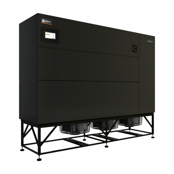
- Page 1 Liebert® CW™ Thermal Management System Installer/User Guide 305 kW, 375 kW, 415 kW Capacity, 50/60 Hz...
- Page 2 The products covered by this instruction manual are manufactured and/or sold by Vertiv. This document is the property of Vertiv and contains confidential and proprietary information owned by Vertiv. Any copying, use or disclosure of it without the written permission of Vertiv is strictly prohibited.
-
Page 3: Table Of Contents
8.1.1 Replacing the Filters 8.2 Fan Maintenance 8.2.1 Fan Assembly Troubleshooting 8.2.2 Fan Impellers 8.2.3 Blower-motor Lubrication 8.2.4 Removing Fan Assembly 8.3 Condensate-drain and Condensate-pump System Maintenance 8.3.1 Condensate Drain 8.3.2 Condensate Pump Vertiv | Liebert® CW™ Installer/User Guide |... - Page 4 9 Preventive Maintenance Checklist Appendices Appendix A: Technical Support and Contacts Appendix B: Submittal Drawings Vertiv | Liebert® CW™ Installer/User Guide |...
-
Page 5: Important Safety Instructions
IMPORTANT SAFETY INSTRUCTIONS SAVE THESE INSTRUCTIONS This manual contains important safety instructions that should be followed during the installation and maintenance of the Liebert® CW. Read this manual thoroughly before attempting to install or operate this unit. Only qualified personnel should move, install or service this equipment. Adhere to all warnings, cautions, notices and installation, operating and safety instructions on the unit and in this manual. - Page 6 Read all of the following instructions and verify that all lifting and moving equipment is rated for the weight of the unit before attempting to move, lift, remove packaging from or prepare the unit for installation. Vertiv | Liebert® CW™ Installer/User Guide...
- Page 7 WARNING! Risk of improper wire sizing/rating and loose electrical connections. Can cause overheated wire and electrical connection terminals resulting in smoke, fire, equipment and building damage, injury or death. Use correctly sized copper wire only and verify that all electrical connections are tight before turning power On. Check all electrical connections periodically and tighten as necessary.
- Page 8 Automotive antifreeze is unacceptable and must NOT be used in any glycol fluid system. Use only HVAC glycol solution that meets the requirements of recommended industry practices. Do not use galvanized pipe. Vertiv | Liebert® CW™ Installer/User Guide...
- Page 9 NOTICE Risk of no-flow condition. Can cause equipment damage. Do not leave the water/coolant fluid- supply circuit in a no-flow condition. Idle fluid allows the collection of sediment that prevents the formation of a protective oxide layer on the inside of tubes. Keep unit switched On and water/coolant fluid-supply circuit system operating continuously.
- Page 10 This page intentionally left blank Vertiv | Liebert® CW™ Installer/User Guide...
-
Page 11: Nomenclature And Components
1 NOMENCLATURE AND COMPONENTS This section describes the number for Liebert® CW units and components. 1.1 Liebert CW Model-number Nomenclature The following tables describe each digit of the configuration number. The 14-digit model number consists of the first 10 digits and last 4 digits of the configuration number. - Page 12 S = Dual locking disconnect with reversing starter + Capacitive buffer Digit 18 = Option packages 0 = None L = Low-voltage terminal package R = Remote-humidifier contact D - Low-voltage terminal package + Remote-humidifier contact Vertiv | Liebert® CW™ Installer/User Guide...
- Page 13 Table 1.5 CW Model-number Digit Definitions (continued) Digit Description Digit 19 = Monitoring B = Base Comms & Connectivity X = Base Comms + Etherernet +RS485 (SFA) R = Base Comms +SiteScan RS485 Expansion ( SFA) Digit 20 = Sensors 0 = None S = Smoke H = High-temperature...
-
Page 14: Component Location
The unit component locations are described in the submittal documents included in the Submittal Drawings on page 45. The following table lists the relevant documents by number and title. Table 1.6 Component-location Drawings Document Number Title DPN004861 Component Location, Horizontal Discharge DPN004899 Component Location, Bottom Discharge Vertiv | Liebert® CW™ Installer/User Guide... -
Page 15: Pre-Installation Preparation And Guidelines
Allow at least the minimum recommended clearances for maintenance and service. See the appropriate submittal drawings for dimensions. • We recommend installing an under-floor water detection system. Contact your Vertiv representative for information. 2.1 Planning Dimensions The unit, floor stand, and plenum dimensions are described in the submittal documents included in the Submittal Drawings on page 45. -
Page 16: Connections And System Setup
See Piping Requirements on page 23. • If seismic requirements apply, consult your Vertiv representative for information about a seismic-rated floor stand. 2.3 Operating Conditions The Liebert® CW must be operated in a conditioned space within the operating envelope that ASHRAE recommends for data centers. -
Page 17: Equipment Inspection And Handling
Verify that the labeled equipment matches the bill of lading. • Carefully inspect all items for visible or concealed damage. • Report damage immediately to the carrier and file a damage claim with a copy sent to Vertiv or to your sales representative. 3 Equipment Inspection and Handling... -
Page 18: Packaging Material
20 ft (5 m) or farther from the unit. • Always refer to the location of the center-of-gravity indicators when lifting the unit, see Figure 3.1 below. Figure 3.1 Center-of-gravity indicator Vertiv | Liebert® CW™ Installer/User Guide... -
Page 19: Unpacking The Unit
3.3 Unpacking the Unit Refer to 3.3 above: • On units with domestic packaging, remove the exterior stretch wrap packaging from around the unit and any protective corner and side packaging planks. • On units with export packaging, remove the metal spring clips that secure the top and side panels of the crate. -
Page 20: Removing The Unit From The Skid
Referring to Figure 3.3 below, use a 9/16-in. socket driver to remove the lag screws (24 total) from the 4 corner brackets to detach the unit from the skid. Figure 3.3 Remove corner brackets Vertiv | Liebert® CW™ Installer/User Guide... - Page 21 2. Using the provided rigging-fastener kit and the instructions included in the kit, install the rigging hardware for lifting the unit from the skid. Figure 3.4 below, shows an example of one of the eye nuts installed. Figure 3.4 Rigging-fastener eye nut installed 3 Equipment Inspection and Handling...
- Page 22 3. Attach the recommended rigging equipment to the eye-nuts installed in Step 2. 4. Using the rigging equipment, lift the unit from the skid, and remove the skid from under the unit, see Figure 3.5 below. Figure 3.5 Lifting unit and removing skid Vertiv | Liebert® CW™ Installer/User Guide...
- Page 23 5. Use the rigging equipment to move the unit to the final installation location, see Figure 3.6 below. Figure 3.6 Moving the unit with rigging 3 Equipment Inspection and Handling...
- Page 24 This page intentionally left blank Vertiv | Liebert® CW™ Installer/User Guide...
-
Page 25: Electrical Connections
4 ELECTRICAL CONNECTIONS Three-phase electrical service is required for all models. Electrical service must conform to national and local electrical codes. Refer to equipment nameplate regarding wire size and circuit protection requirements. Refer to electrical schematic when making connections. Refer the appropriate submittal drawing, listed in Table 4.1 on the next page, for electrical service entrances into unit. - Page 26 Connection Locations, Bottom-discharge, Front-left facing electrical/piping compartment Connection Locations, Gallery with horizontal-discharge, Front-right facing electrical/piping DPN004924 compartment Connection Locations, Gallery with horizontal-discharge, Front-right facing electrical/piping DPN004925 compartment Unit-to-Unit Networking DPN004351 Liebert® iCOM Unit-to-unit Network Connections Vertiv | Liebert® CW™ Installer/User Guide...
-
Page 27: Piping Requirements
5 PIPING REQUIREMENTS All fluid connections to the unit, with the exception of the condensate drain, are sweat copper. Factory- installed piping brackets must not be removed. Field-installed piping must be installed in accordance with local codes and must be properly assembled, supported, isolated and insulated. Avoid piping runs through noise-sensitive areas, such as office walls and conference rooms. -
Page 28: Drain Fluid Connections
The drain line must be rigid enough that it does not sag between supports, which unintentionally creates traps. • The drain line must comply with all applicable codes. • We recommend installing monitored, under-floor leak-detection equipment. Vertiv | Liebert® CW™ Installer/User Guide... -
Page 29: Condensate-Pump Drain Line Requirements
5.1.2 Condensate-pump Drain Line Requirements NOTICE Risk of water backing up in the drain line. Leaking and overflowing water can cause equipment and building damage. Sagging condensate drain lines may inadvertently create an external trap. Observe the following requirements when installing and routing the drain line: •... - Page 30 The shut-off valves must be sized to close-off against the maximum coolant-fluid system pressure in case of a catastrophic fluid leak. Vertiv | Liebert® CW™ Installer/User Guide...
-
Page 31: Leak Checking For Unit And Field-Installed Piping
5.2.1 Leak Checking for Unit and Field-installed Piping The fluid systems in the Liebert® CW are factory-checked for leaks and may be shipped with holding charge. At installation, check all fluid circuits for leaks. NOTE: We recommend isolating the unit with field-installed shutoff valves during leak checking of field-installed piping. - Page 32 This page intentionally left blank Vertiv | Liebert® CW™ Installer/User Guide...
-
Page 33: Checklist For Completed Installation
6 CHECKLIST FOR COMPLETED INSTALLATION 6.1 Moving and Placing Equipment Unpack and check received material. 2. Proper clearance for service access has been maintained around the equipment. 3. Equipment is level and mounting fasteners are tight. 6.2 Electrical Installation Checks Supply voltage and phase matches equipment nameplate. - Page 34 This page intentionally left blank Vertiv | Liebert® CW™ Installer/User Guide...
-
Page 35: Initial Start-Up Checks And Commissioning Procedure For Warranty Inspection
This information must be completed and forwarded to validate warranty. • Contact your local sales representative or technical support if you have any questions or problems during unit start-up and commissioning. Visit https://www.Vertiv.com/en-us/support/ or call 1-800-222-5877 for contacts. 7 Initial Start-up Checks and Commissioning Procedure For Warranty Inspection... - Page 36 This page intentionally left blank Vertiv | Liebert® CW™ Installer/User Guide...
-
Page 37: Maintenance
8 MAINTENANCE WARNING! Arc flash and electric shock hazard. Open all local and remote electric power-supply disconnect switches, verify with a voltmeter that power is Off and wear appropriate, OSHA-approved personal protective equipment (PPE) per NFPA 70E before working within the electric control enclosure. -
Page 38: Filters
NOTICE Risk of improper filter installation. Can cause filter collapse and airflow reduction. To maximize the performance and reliability of the equipment, use only Vertiv filters. Contact your Vertiv representative to order replacement filters. Verify that filters are installed and positioned so the air-flow direction marked on the filter is the same direction as unit air flow. -
Page 39: Replacing The Filters
8.1.1 Replacing the Filters WARNING! Risk of contact with high-speed rotating fan blades. Can cause serious injury or death. Open all local and remote electric power-supply disconnect switches, verify with a voltmeter that power is off, and verify that all fan blades have stopped rotating before working in the unit cabinet or on the fan assembly. -
Page 40: Fan Maintenance
10 minutes after power is disconnected. Wait 10 minutes after power is verified as off before working within the electric control/connection enclosures. Use only fully- trained and qualified HVAC technicians to perform maintenance on the fans. Vertiv | Liebert® CW™ Installer/User Guide... -
Page 41: Fan Impellers
Consult the factory for fan-assembly maintenance and removal instructions. Do not attempt to service or remove the fans without first contacting Vertiv support at 1-800-222-5877. 8.2.3 Blower-motor Lubrication The motor is initially lubricated at the factory. -
Page 42: Removing Fan Assembly
8.2.4 Removing Fan Assembly Do not attempt to remove the fan assemblies without first contacting Vertiv Technical Support at 1-800- 222-5877. 8.3 Condensate-drain and Condensate-pump System Maintenance 8.3.1 Condensate Drain Check for and clear obstructions in tubing during routine maintenance. -
Page 43: Preventive Maintenance Checklist
9 PREVENTIVE MAINTENANCE CHECKLIST Source: DPN002952, Rev. 4 Inspection Date Job Name Indoor Unit Model # Indoor Unit Serial Number # Room Temperature/Humidity ° % Ambient Temperature ° Not all units will have all components. To determine your unit’s configuration, compare the Indoor Unit Model # above and the information in the Components and Nomenclature section. - Page 44 Condensate Pump (if equipped) Check for debris in sump 2. Check operation of float(s) (free movement) 3. Check/Clean discharge check valve Electrical Panel Check fuses 2. Check contactors for pitting (Replace if pitted) 3. Check/Re-torque wire connections Vertiv | Liebert® CW™ Installer/User Guide...
- Page 45 MAINTENANCE NOTES Name Signature Company Make photocopies for your records. Compare readings/information to previous maintenance worksheet. To locate your local Vertiv representative for Vertiv-engineered parts, check https://www.Vertiv.com/en- us/support/ or Call 1-800-222-5877. 9 Preventive Maintenance Checklist...
- Page 46 This page intentionally left blank Vertiv | Liebert® CW™ Installer/User Guide...
-
Page 47: Appendices
APPENDICES Appendix A: Technical Support and Contacts A.1 Technical Support/Service in the United States Vertiv™ Corporation 24x7 dispatch of technicians for all products. 1-800-543-2378 Liebert® Thermal Management Products 1-800-543-2778 Liebert® Channel Products 1-800-222-5877 Liebert® AC and DC Power Products 1-800-543-2378 A.2 Locations... - Page 48 This page intentionally left blank Vertiv | Liebert® CW™ Installer/User Guide...
-
Page 49: Appendix B: Submittal Drawings
Appendix B: Submittal Drawings The submittal drawings are in the order of document part number (DPN). Table B.1 below, groups the drawings by topic/application. Table B.1 Submittal-drawings Contents Document Number Title Component Location DPN004861 Component Location, Horizontal Discharge DPN004899 Component Location, Bottom Discharge Planning Dimensions - Downflow Units DPN004862 Cabinet and Plenum Dimensional Data, Downflow, Horizontal Discharge... - Page 50 Connection Locations, Bottom-discharge, Front-left facing electrical/piping compartment Connection Locations, Gallery with horizontal-discharge, Front-right facing electrical/piping DPN004924 compartment Connection Locations, Gallery with horizontal-discharge, Front-right facing electrical/piping DPN004925 compartment Unit-to-Unit Networking DPN004351 Liebert® iCOM Unit-to-unit Network Connections Vertiv | Liebert® CW™ Installer/User Guide...
- Page 51 LIEBERT DS, DSE, CW, PDX & PCW UNIT TO UNIT NETWORK CONNECTIONS RS485 SITE AND BMS COMMUNICATION CONNECTIONS ETHERNET DETAIL A ETHERNET CABLE (FIELD SUPPLIED) UNIT-TO-UNIT NETWORKING SWITCH (FIELD SUPPLIED) iCOM MICROPROCESSOR AND I/O BOARD TO / FROM OTHER NETWORKED UNITS P100 P95 DVI-D CABLE CONNECTION TO 7-INCH ICOM DISPLAY...
- Page 52 LIEBERT DS, DSE, CW, PDX & PCW UNIT TO UNIT NETWORK CONNECTIONS ETHERNET CABLE (FIELD SUPPLIED) iCOM iCOM MICROPROCESSOR MICROPROCESSOR AND I/O BOARD AND I/O BOARD P100 P100 P95 DVI-D CABLE CONNECTION TO 7-INCH ICOM DISPLAY P100 POWER SUPPLY TO P95 DVI-D CABLE CONNECTION 7-INCH ICOM DISPLAY TO 7-INCH ICOM DISPLAY...
- Page 53 LIEBERT CW COMPONENT LOCATION DIAGRAM CW305, 375, 415 W/ HORIZONTAL DISCHARGE 1. Blower/Motor (Typical 3) 2. Line Reactor Transformers (Typical 3) Notes: 1. Electrical Compartment (item #6) shown on left side of unit. 3. Evaporator Coil Unit may be ordered with Electrical Compartment on either side, or with Electrical Compartment facing into Gallery space.
- Page 54 LIEBERT CW CABINET DIMENSIONAL DATA CW305, 375, 415 W/ HORIZONTAL DISCHARGE 115 3/8" 2929mm Outside of Duct Flange Rear of Unit (Gallery Side) 60 3/4" 1544mm 53 1/8" 1348mm Outside of 60 1/8" Duct Flange 1527mm For Unit Disassembly Data 120 1/8"...
- Page 55 LIEBERT CW PRIMARY CONNECTION LOCATIONS CW305, 375, 415 DATA HALL W/ HORIZONTAL DISCHARGE FRONT LEFT FACING ELECTRICAL/PIPING COMPARTMENT Data Hall Side Top View Bottom View Top View Bottom View POINT Description Connection Size/Opening X in. (mm) Y in. (mm) X in. (mm) Y in.
- Page 56 LIEBERT CW ELECTRICAL FIELD CONNECTIONS CW305, 375, 415 DOWNFLOW MODELS STANDARD ELECTRICAL CONNECTIONS 1. High voltage entrance - Located in bottom and top of box (quantity 2). Raceway in front left corner of enclosure for routing high voltage wires thru enclosure.
- Page 57 LIEBERT CW ELECTRICAL FIELD CONNECTIONS CW305, 375, 415 DOWNFLOW MODELS OPTIONAL ELECTRICAL CONNECTIONS 9. Condensate alarm (with condensate pump option) - On pump high water indication, normally open dry contact is closed across terminals 88 & 89 for remote indication. 1 AMP, 24VAC max load. Use Class 1 field supplied wiring.
- Page 58 LIEBERT CW ELECTRICAL FIELD CONNECTIONS CW305, 375, 415 DOWNFLOW MODELS RAD1 ALARM RAD2 INPUTS CPSS RAD4 COMMON ALARMS EXTRA COMMON ALARM See Detail A CONDENSATE PUMP LIQUITECT SHUT DOWN MAIN FAN ENABLED REMOTE HUMID STARTER RA / RB EXTRA REMOTE...
- Page 59 LIEBERT CW AIRFLOW SCHEMATIC CW305, 375, 415 DOWNFLOW UNIT W/ HORIZONTAL DISCHARGE 115 3/8" 2 3/8" 2929mm 60mm Outside of Return Air Duct Flange from Data Center 53 1/8" 1348mm Outside of Duct Flange 61" 1550mm Section 4 3/8" 111mm 1 3/4"...
- Page 60 LIEBERT CW FLOORSTAND DIMENSIONAL DATA CW305, 375, 415 2 1/2" 33 7/8" 36 3/8" 64mm 860mm 924mm Typ. (2) Plcs. 28 1/8" 43 1/2" 715mm 1105mm Typ. (2) Plcs. Typ. (2) Plcs. 56 1/4" 1430mm Typ. Top View 33 7/8"...
- Page 61 LIEBERT CW FLOOR PLANNING DIMENSIONAL DATA FOR ADJACENT CW305, 375, 415 UNITS Gasketing shown is for pictorial purposes only to show edges of unit that require gap sealing. Gasketing and method to be provided and applied by others in the field.
- Page 62 LIEBERT CW FLOOR PLANNING DIMENSIONAL DATA FOR ADJACENT CW305, 375, 415 UNITS Gasketing shown is for pictorial purposes only to show edges of unit that require gap sealing. Gasketing and method to be provided and applied by others in the field.
- Page 63 LIEBERT CW INSTALLATION & SERVICE CLEARANCE DATA CW305-415 PERIMETER INSTALLATION AND SERVICE CLEARANCE HORIZONTAL DISCHARGE Wall Full Unit and Electrical Panel Access Piping & Cables can be routed in this zone. 66" (1676mm) Full Unit and Electrical Panel Access Data Hall Notes: 1.
- Page 64 LIEBERT CW INSTALLATION & SERVICE CLEARANCE DATA CW305-415 PERIMETER INSTALLATION AND SERVICE CLEARANCE BOTTOM DISCHARGE Wall Piping and Cables can be routed in this zone. Unit Disassembly access and Electrical Panel access 66" (1676mm) Full Unit and Electrical Panel Access...
- Page 65 LIEBERT CW INSTALLATION & SERVICE CLEARANCE DATA CW305-415 GALLERY INSTALLATION AND SERVICE CLEARANCE Piping and Cables can be routed in this zone. Data Hall Wall Gallery Side 66" (1676mm) Electrical Panel Access Notes: 1. Electrical Compartment is shown on the left side of the unit.
- Page 66 LIEBERT CW COMPONENT LOCATION DIAGRAM CW305, 375, 415 W/ BOTTOM DISCHARGE 1. Blower/Motor (Typical 3) 2. Line Reactor Transformers (Typical 3) 3. Evaporator Coil 4. Air Filters 5. Condensate Pump (optional, shipped loose) 6. Electric Panel 7. THD Mitigation Device (optional) 8.
- Page 67 LIEBERT CW CABINET DIMENSIONAL DATA CW305, 375, 415 W/ BOTTOM DISCHARGE 115 3/8" 2929mm Outside of Duct Flange Rear of Unit 61" 53 1/8" 1550mm 1348mm Outside of 60 1/8" 1527mm Duct Flange 120 1/8" 1 3/4" 3050mm 44mm Duct...
- Page 68 LIEBERT CW PRIMARY CONNECTION LOCATIONS CW305, 375, 415 W/ BOTTOM DISCHARGE FRONT RIGHT FACING ELECTRICAL/PIPING COMPARTMENT Top View Bottom View Top View Bottom View POINT Description Connection Size/Opening X in. (mm) Y in. (mm) X in. (mm) Y in. (mm)
- Page 69 LIEBERT CW PRIMARY CONNECTION LOCATIONS CW305, 375, 415 W/ BOTTOM DISCHARGE FRONT LEFT FACING ELECTRICAL/PIPING COMPARTMENT Top View Bottom View Top View Bottom View POINT Description Connection Size/Opening X in. (mm) Y in. (mm) X in. (mm) Y in. (mm)
- Page 70 LIEBERT CW AIRFLOW SCHEMATIC CW305, 375, 415 DOWNFLOW UNIT W/ BOTTOM DISCHARGE 115 3/8" 2929mm Duct Flange Return Air from Data Center 53 1/8" 1348mm Duct Flange 1 3/4" 44mm Duct Flange Supply Air to Data Center 115 3/4" 2940mm 55 3/4"...
- Page 71 LIEBERT CW PRIMARY CONNECTION LOCATIONS CW305, 375, 415 DATA HALL W/ HORIZONTAL DISCHARGE FRONT RIGHT FACING ELECTRICAL/PIPING COMPARTMENT Data Hall Side Top View Gallery Side Bottom View Data Hall Side Top View Bottom View POINT Description Connection Size/Opening X in. (mm) Y in.
- Page 72 LIEBERT CW PRIMARY CONNECTION LOCATIONS CW305, 375, 415 GALLERY W/ HORIZONTAL DISCHARGE FRONT RIGHT FACING ELECTRICAL/PIPING COMPARTMENT Data Hall Side Top View Gallery Side Bottom View Data Hall Side Top View Bottom View POINT Description Connection Size/Opening X in. (mm) Y in.
- Page 73 LIEBERT CW PRIMARY CONNECTION LOCATIONS CW305, 375, 415 GALLERY W/ HORIZONTAL DISCHARGE FRONT LEFT FACING ELECTRICAL/PIPING COMPARTMENT Data Hall Side Top View Gallery Side Bottom View Top View Bottom View POINT Description Connection Size/Opening X in. (mm) Y in. (mm) X in.
- Page 74 LIEBERT CW GENERAL ARRANGEMENT DIAGRAM CW305, 375, 415 Air Flow Valve Actuator Bleed Valve Chilled Water Return Chilled Water Coil Chilled Water Supply Shut 2-Way Chilled Valves Water Valve Hose Bibs FACTORY PIPING FIELD PIPING Notes: 1. Components are not supplied by Liebert, but are required for proper circuit operation and maintenance.
- Page 75 Vertiv | Liebert® CW™ Installer/User Guide...
- Page 76 VertivCo.com | Vertiv Headquarters, 1050 Dearborn Drive, Columbus, OH, 43085, USA © 2018 Vertiv Co. All rights reserved. Vertiv and the Vertiv logo are trademarks or registered trademarks of Vertiv Co. All other names and logos referred to are trade names, trademarks or registered trademarks of their respective owners. While every precaution has been taken to ensure accuracy and completeness herein, Vertiv Co.
Need help?
Do you have a question about the Liebert CW and is the answer not in the manual?
Questions and answers