
Related Manuals for GW Instek GSM-20H10


Summary of Contents for GW Instek GSM-20H10
- Page 1 Programmable High Precision DC Source Meter GSM-20H10 Quick Start Guide GW INSTEK PART NO. 82SM-20H10M01 ISO-9001 CERTIFIED MANUFACTURER...
- Page 2 Copyright Statement This manual contains proprietary information, which is protected by copyright. All rights are reserved. No part of this manual may be photocopied, reproduced or translated to another language without prior written consent of Good Will company. The information in this manual was correct at the time of printing. However, Good Will continues to improve products and reserves the rights to change specification, equipment, and maintenance procedures at any time without notice.
-
Page 3: Table Of Contents
Table of Contents Table of Contents OVERVIEW ..............2 Front Panel ............3 Rear Panel .............. 8 Terminal Connection ........... 10 BASIC OPERATION ........... 16 Preparation ............16 Source Function ........... 18 Measure Function ..........33 Limit Function ............. 46 Sequence Function .......... -
Page 4: Overview
OVERVIEW VERVIEW The GSM combines a precise, low-noise, highly stable DC power supply with a low-noise, high-impedance multimeter. It has 0.012% basic accuracy with 6 digit resolution. At 4 digits display resolution (Medium), the GSM delivers 520 readings/second over the IEEE-488 bus. At 3 digits display resolution (Fast), it can read up to 2000 readings/second into its internal buffer. -
Page 5: Front Panel
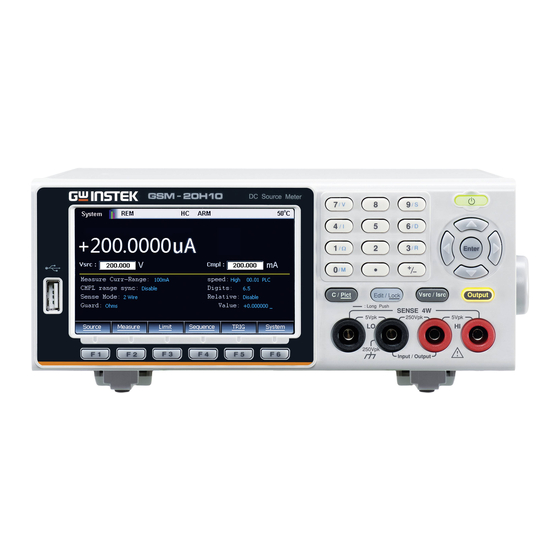
GSM-20H10 Quick Start Guide Front Panel LCD Display Numberpad and Power Secondary function key on/off button USB host port Auxiliary Funtion key Front panel Input/ function key Output terminals Display & Parameter Power on Display (Source) - Page 6 OVERVIEW Description The display is used primarily to program source and compliance values and display the real measurement readings. The area is divided as follows. ① Status and Error messages Status and error messages are displayed momentarily, which are located on the top of the display, indicate various states of operation.
- Page 7 GSM-20H10 Quick Start Guide Control Panel Long press for at least 2 seconds to Power turn on or turn off the power supply standby of the instrument (turn on the AC switch power switch on the rear panel first, and make the GSM standby light...
- Page 8 OVERVIEW The Enter key is used to confirm the selection of any settings or parameters and to exit after a setting is complete. Edit /Lock The instrument must be in the edit mode to set source and compliance values.The edit mode is selected by short pressing the Edit/Lock key.
- Page 9 GSM-20H10 Quick Start Guide Ω: Measure and display the Resistor M: Measure and display the calculation result Measurement operation under each function: Source: V, I Measure: V, I, Ω, M Limit: V, I, Ω, M Sequence: V, I, Ω, M...
-
Page 10: Rear Panel
Heat sink fan Inputs/Outputs Terminals AC power Power on or power off the main switch circuit, GSM-20H10 is in standby state after pressing I, and the standby light on the front panel is red. I->on, O->off AC input The AC input accepts 100 to 240±... - Page 11 GSM-20H10 Quick Start Guide GPIB port GPIB slave port for remote control. Abides to IEEE488.2 (SCPI) protocol. LAN port LAN port for remote control. RS-232 port RS-232 device port for remote control. Digital I/O There are 15 I/O ports: one +5V...
-
Page 12: Terminal Connection
OVERVIEW Terminal Connection Front/Rear Terminals Terminals The INPUT/OUTPUT (HI and LO) and SENSE (HI and LO) terminals are accessible from both the front and rear panels. The V.Ω GUARD and GUARD SENSE terminals are only accessible from the rear panel. Front/Rear The front/rear terminal can be selected through the terminals... - Page 13 GSM-20H10 Quick Start Guide WARNING: To prevent electric shock and damages to the GSM-20H10, DO NOT exceed the maximum allowable voltage differentials shown in terminals. The front and rear terminals of the GSM are rated for connection to circuits rated Installation Category I only.
- Page 14 OVERVIEW WARNING: There is no internal connection between earth ground and INPUT/OUTPUT LO terminal of the GSM.Therefore, hazardous voltages (>30V rms) maybe appear on that LO terminal. Typically, this can occur when the GSM is operating in any mode where the output changes rapidly, such as quick, pulsed waveforms that can be generated using the ZERO, AUTO-OFF output state, or fast pulse sweep operations.
- Page 15 GSM-20H10 Quick Start Guide When the output is turned off in 4-wire sensing mode, for safety reasons, the Sense mode automatically returns to 2-wire. When the output is turned on, the Sense mode automatically restores to 4-wire. WARNING: When sourcing voltage in remote sense, make sure the sense leads are connected to the DUT.
- Page 16 OVERVIEW Sense and Guard Selections Sense When using the SENSE HI and LO terminals of the selection GSM, 4-wire remote sensing must be selected. When not using these terminals, 2-wire local sensing must be selected. NOTE: When Sense mode or Guard settings are changed, the OUTPUT will turn off.The GSM defaults to the 2-wire mode when the output is off, regardless of the sense setting.
- Page 17 GSM-20H10 Quick Start Guide Front panel Perform the following steps to change the Guard guard selection: selection 1. Click the Edit/Lock button and direction keys to make the cursor stay in the Guard setting box. 2. Press Enter button, use the direction keys to select Ohms or Cable, and press Enter to exit programming.
-
Page 18: Basic Operation
BASIC OPERATION ASIC OPERATION Preparation Funtion Overview Description From the front panel, the GSM-20H10 can be configured to perform the following operations: Source Funtion: • Source voltage — Display current or voltage measurement reading • Source current — Display voltage or current... - Page 19 GSM-20H10 Quick Start Guide required value: Press the numeric key to input the required value, and press the sign key firstly if a negative value is needed, then press Enter to exit editing. Press the left and right arrow keys, the...
-
Page 20: Source Function
BASIC OPERATION Source Function V/I Output Range Source or According to the settings and connection with the Sink load, the GSM can operate in any one of the four quadrants. The figure below shows the four operating quadrants of the GSM. When operateing in the first (I) or third (III) quadrant, the GSM operates as a power source (V and I have the same polarity). - Page 21 GSM-20H10 Quick Start Guide Front Panel Programming Interface Default power on interface Source interface: the parameter setting consists of 3 areas, marked as ①②③ in the picture, press Edit/Lock key to toggle between ①②③. When the cursor is moved to area ① or area ②, use the up and down direction keys to...
- Page 22 BASIC OPERATION measurement reading between Voltmeter and Amperemeter. Parameter Description and Operation Vsrc/Isrc Set the power supply as V-Source or I-Source. When it is in the editing state (press Edit/Lock key to make the number digits turn into white characters on a black background), the range can be changed by the up and down keys.
- Page 23 GSM-20H10 Quick Start Guide current. When it is in the editing state (press Edit/Lock key to make the number digits turn into white characters on a black background), the range can be changed by the up and down keys. Range setting The operations is the same as Vsrc/Isrc setting.
- Page 24 BASIC OPERATION If Measure curr-range or Measure vol-range option selects Auto, the SDM cycle will repeatedly read the measured value in the new range. Each SDM cycle includes source delay time. Range setting: Press the Edit/Lock key to select the Measure volt-range or Measure curr-range option, press the Enter key to make it in the editing state, use the up and down keys to select the required...
- Page 25 GSM-20H10 Quick Start Guide interference and protect the users from being injured by hazardous voltage on the guard shield (or plate). The CABLE guard selection provides a high-impedance (~10kΩ) driven guard to prevent positive feedback, which could cause oscillations when using shielded cables. Cable guard is used to drive the shields of cables and test fixtures.
- Page 26 BASIC OPERATION no leakage current passes. Therefore, the current measured by the GSM is the current flowing through the device under test. NOTE Cable guard must choose the connection shown in Figure below. The plate of the fixture should be connected to the Input/Output LO terminal to reduce interference.
- Page 27 GSM-20H10 Quick Start Guide Rg≥1kΩ When the impedance Rg from the V.Ω GUARD terminal to the Input/ Output LO terminal is more than 1kΩ, the voltage drop of the lead impedance (about 1Ω) of the V.Ω GUARD terminal is very small relative to Rg, and the voltage drop of R1 is approximately zero, and no leakage current flows through R1.
- Page 28 BASIC OPERATION Rg<1 kΩ The voltage drop on the test lead (about 1Ω) of the V.Ω GUARD terminal is significant respectively to the voltage drop on the Rg, causing the potential at the connection between R1 and the V.Ω GUARD terminal to be lower than the potential at the connection between R1 and the Input/Output HI terminal.
- Page 29 GSM-20H10 Quick Start Guide <1kΩ In this situation, 4-Wire sense mode should be used. When Rg<1kΩ, this connection method is 6-Wire ohms guard measurement. When using this measurement method, select GUARD output-off states for Off state option. NOTE: Ohms guard cannot be selected in 1A range (as source or meter).
- Page 30 BASIC OPERATION will be less than the Input/Output terminal voltage and affect the measurement data. Guard sense operation is automatic, and it can be used directly after connecting the test leads without setting. Speed Set the data sampling speed, that is, the calculation processing time of A/D conversion, which is determined by the number of power cycles.
- Page 31 GSM-20H10 Quick Start Guide NOTE: Relative Value is valid to all the ranges. For example, if the Relative Value is set to 5V in the 20V range, if the range is changed to 2V or 200V, the Relative Value is still 5V.
- Page 32 BASIC OPERATION and the OVP symbol is displayed in the status bar. When the output exceeds the OVP Value, the OVP status indicator is lit in red , indicating that the OVP status is entered, and the actual output is limited to the programmed OVP Value.
- Page 33 GSM-20H10 Quick Start Guide control to the Isrc trig control box, press Enter and the Arrow keys to select Enable or Disable, when selecting Enter, input the value in the Scale factor box.This function is used for SRC-MEM sequence. Output Operation...
- Page 34 BASIC OPERATION Source-measure operation is in progress TRIG Select external trigger source (Tlink, Rising Edge, Falling Edge, Edge) When the overvoltage protection function is disable, the OVP mark is gray, when the OVP function is enable, the OVP mark is black, and the mark is red when the OVP function is triggered.
-
Page 35: Measure Function
GSM-20H10 Quick Start Guide Measure Function Measurement interface Display The Measure interface is basically the same as the Source (only increase setting items for resistor measurement). The parameter setting area is composed of 3 areas shown as①②③ in Figure above. Press the Edit/Lock key to switch between ①②③. - Page 36 BASIC OPERATION V/I Meter Setting Press the F2 (Measure) key to display the measurement interface. Under non-numerical programming, press the 7/V key to set as the voltmeter (Source must be Isrc), or press the 4/I key to select as the current meter (Source must be Vsrc).
- Page 37 GSM-20H10 Quick Start Guide source, which may damage the external source or test circuit. NOTE: When only measuring voltage or current, connect the device under test and the GSM with 2-wire mode. Ohmmeter Measurement Press the F2 (Measure) key, and then press the interface "1/Ω"...
- Page 38 BASIC OPERATION the resistor to be measured to obtain the highest measurement accuracy. Generally, the current range corresponding to the resistor range is as follows: Range(Ω) 200k 2M 20M 200M I-Source range -- 100mA 10mA 1mA 100uA 10uA 1uA 1uA 100nA Cmpl is used to set the compliance value, and the lowest allowable compliance value depends on the load and the source value.
- Page 39 GSM-20H10 Quick Start Guide CompOhms Ohm compensation function. The existence of thermoelectric potential affects the measurement accuracy of low value resistor, CompOhms function can be used to reduce the influence of offset voltage. Calculated as follows: CompOhms Ω=(V2-V1)/(I2-I1) V1 represents the voltage measurement reading...
- Page 40 BASIC OPERATION reading measured by the second programmed source value. When calculating the Vceoff value, two voltage source values need to be set. VarAlpha The alpha (α) value defines the characteristics of the varistor. The definition of α value is expressed by the following formula: α=log(I2/I1)/log(V2/V1) V1 represents the voltage measurement reading...
- Page 41 GSM-20H10 Quick Start Guide Speed/Digits/ *Press “9/S”, “6/D” and “3/R” to quickly operate Relative to set Speed/ Digits/ Relative option When it comes to resistance measurement, the following parameters require to be programmed as: Measure It is used to set a sensitive range for the resistor under...
- Page 42 BASIC OPERATION Range(Ω) 200k 2M 20M 200M I-Source range -- 100mA 10mA 1mA 100uA 10uA 1uA 1uA 100nA Setting: Move the cursor to the setting item (it turns into a red letter with a gray background), and press Enter. After the up and down arrow signs appear, operate the up and down direction buttons to select the appropriate method (Manual or Auto), and then press Enter to confirm.
- Page 43 GSM-20H10 Quick Start Guide Parameter setting of calculation function Power This calculation function uses the measurement voltage value multiplying the measurement current value to obtain the Power measurement reading, and the unit of the displayed value is watts. Operation steps:...
- Page 44 BASIC OPERATION Finally, turn on the Output key, and the measurment rasistance will be displayed. NOTE: When programming the value of V1 and V2 (or I1 and I2), the up and down direction keys can switch the range of voltage or current. The value should be set in the most suitable range according to the range of the resistor to be measured.
- Page 45 GSM-20H10 Quick Start Guide Operate the Enter key, the arrow keys and the number keys to set the values of I1 and I2 in sequence. Press F5 (Cancel) to return to the Measure interface. Press the 0/M key to switch to the calculation Measure interface.
- Page 46 BASIC OPERATION Measurement Operations Steps Generally there are the following steps: Connect the external test leads (front-panel or rear-panel) according to the requires of the test For rear-panel output, set it according to System->Control->Rear. Set Vsrc or Isrc and Cmpl on the front panel Set other parameters in the parameter area (Measure interface) Select the required measurement reading...
- Page 47 GSM-20H10 Quick Start Guide When the overvoltage protection function is disable, the OVP mark is gray, when the OVP function is enable, the OVP mark is black, and the mark is red when the OVP function is triggered. When reading failure or invalid calibration steps occur,...
-
Page 48: Limit Function
BASIC OPERATION Limit Function Display interface Description Limit test classification: There are three types of limits: compliance value (Cmpl), coarse limit (Limit 2), fine limit (limit 3, 5-12). When Output is ON, pressing the F3 (Limit) key will trigger the operation of the limit function as long as the Limit option is set to Enable, and the mark will also appear on the display area. - Page 49 GSM-20H10 Quick Start Guide Limit 1 test (compliance): It is a hardware test, which checks the compliance status of the GSM, and uses the programmed compliance value as the test limit.If the measurement reading is at or above the programmed compliance value, indecating that the GSM is in compliance.
- Page 50 BASIC OPERATION Parameter description and operation Long press F3(Limit) button to enter the setting Setting interface as shown in the figure below: interface There are 5 sub-menus to be programmed respectively: F1(Digout) F2(HW-Limits) F3(SW-Limits) F4(Pass) F5(EOT-Mode) Digout Size Used to control the bits number of digital I/0. Choose 3 or 4 or 16 digits.
- Page 51 GSM-20H10 Quick Start Guide limits, PASS will be displayed. Sorting fail option cannot be set in Grading mode. When Grading is set to Immediate, the measurement process will terminate at the first fail situation. If the measurement reading is less than the Low limit of any of Limit 2, 3, 5-12, the I/O port will output the corresponding Lo_fail value.
- Page 52 BASIC OPERATION Auto clear Used to select the automatic clear function of the digital output (Enable or Disable). If Enable, you can set the pulse width of the pass/fail pattern (delay 0 to 60s) and the Clear pattern of the digital output (0-7 for 3 digits, 0-15 for 4 digits).
- Page 53 GSM-20H10 Quick Start Guide reading is restricted by the compliance value, press the F3 key to display the red FAIL logo; When selecting Out, if the measurement reading is within the compliance limit range, press the F3 key to display the red FAIL logo; if measurement reading is restricted by the compliance value, press the F3 key to display the green PASS logo;...
- Page 54 BASIC OPERATION High Set the high value of the limit range of LIM2, LIM3, LIM5 -LIM12. Hi_fail Setting the high fail pattern value of LIM2, LIM3, LIM5 -LIM12. When the Digout size is 3 digits, the value is 0 to 7, and when the Digout size is 4 digits, the value is 0 to 15.
- Page 55 GSM-20H10 Quick Start Guide When EOT is selected, in the case of 3bit Digout size, the fourth line of the Digital I/O lines automatically outputs a HI pulse at the end of test. When the Digout size is 4bit, the End of test signal is not automatically controlled.
- Page 56 BASIC OPERATION used with an output enable circuit on a device or test fixture. line12-line15: 4 output signal ports of Digtal I/O ports Connection Diagram The measurement method shown in the figure above is used to send the pattern values of the limit test. Load Each open-collector output can be set to high level connection...
- Page 57 GSM-20H10 Quick Start Guide low level to drive the relay. The maximum sink current is 500mA. The connection method is shown in the figure below: Output The digital I/O port provides an output enable Enable control line to be used together with the output control line switch of a test fixture.
- Page 58 BASIC OPERATION by Digital I/O. Allow 100us settling and response time. The digital I/O lines are edge-sensitive, open- collector, and signals must be debounced to avoid unstable operation. Limit Operation Operation Generally there are the following steps: Set up the measurement system. Such as connecting a DUT to the GSM, and can also connecting components to external I/O port according to test requirements.
- Page 59 GSM-20H10 Quick Start Guide whether Auto off is set to Enable or Disable that PZER or FZER will be displayed when Output is turned off. If the programmed V exceeds OVP, “OVP” is • displayed in red on the status bar. At this time, when the Limit function is running, P OVP or F OVP will be displayed accordingly.
-
Page 60: Sequence Function
BASIC OPERATION Sequence Function Display Interface Description This function can be used when different voltage and current waveforms need to be output in practical applications. Users can program the output waveform according to needs. The amplitude range of the output waveform is the range of output voltage or current of the GSM. - Page 61 GSM-20H10 Quick Start Guide Features There are four types of Sequence: Stair, Log, Custom, and SRC-MEM. Stair The output of the waveform depends on the following parameters: Start value, Stop value, Step (Stair) value, Delay value (Determined by Source delay, trigger delay and Speed which can be set separately).
- Page 62 BASIC OPERATION tests, the sequence will jump to the next position in the list. When NEXT is selected in Source memory location, regardless of the limit test PASS or FAIL, the sequence will proceed to the next position in the list. The figure below shows a seven-point sequence branching.
- Page 63 GSM-20H10 Quick Start Guide Parameter Description And Operation Description There are 2 ways to enter the parameter setting interface of Sequence: Long press the F4 (Sequence) key. When Output is turned off, press the F4 key to enter the Sequence data browsing interface, and then press the F1 (Setting) key to enter.
- Page 64 BASIC OPERATION SRC-MEM waveform parameters Start location The points number of SRC-MEM sequence: 1 to 100. Memory save operation: Press the F6 (System) key on the main interface, and then press the F2 (Control) key to enter the following interface: Move the cursor to the Memory save option box, press Enter, enter a number between 1-100, and press Enter, the following dialog box appears:...
- Page 65 GSM-20H10 Quick Start Guide Press Enter, enter a number between 1-100, press Enter, the following dialog box appears, move the cursor to OK button and press Enter, which means to recall the settings in the corresponding memory location indicated by the number in the Memory restore box to present Source interface.
- Page 66 BASIC OPERATION Press the F3 (Single) key to set the parameters of a single point. The time parameters are determined by Source delay, trigger delay and Speed which can be set separately. Other Parameters Counts Set the sequence times, you can choose Finite or Infinite.
- Page 67 GSM-20H10 Quick Start Guide Never: Interrupt is prohibited. Early: Indicates that when the measurement reading is not within the compliance range, an interruption occurs at the beginning of the SDM cycle. Late: Indicates that when the measurement reading is not within the compliance range, an interruption occurs at the end of the SDM cycle.
- Page 68 BASIC OPERATION Sequence Output Operation Generally there are the following steps: Connect the external connection (front panel or rear panel) according to the requirement of test. For rear panel output, set it by System->Control- >Rear. Set Vsrc or Isrc and Cmpl on the front panel. Set other parameters in the parameter area (Sequence interface).
-
Page 69: Trig Function
GSM-20H10 Quick Start Guide TRIG Function Programming Interface Description Long press the F5 (TRIG) button on the main interface to enter the TRIG function setting interface:... - Page 70 BASIC OPERATION Trigger process The trigger mode is composed of the ARM layer and TRIG layer. The process is shown in the figure below:...
- Page 71 GSM-20H10 Quick Start Guide Parameter Description And Operation ARM Layer Press the F1(Arm) button, setting the Arm layer of the TRIG mode, and set the options in the ARM in, ARM count and ARM out. ARM in Source Used to select the trigger source of the Arm layer. It...
- Page 72 BASIC OPERATION turned ON, manually press the F5 (TRIG) key once, the event detection will be triggered to run once. Tlink: When an input trigger is received through the Trigger Link input line, event detection occurs. When selecting Tlink, you can bypass the Arm Event Detector by selecting the Bypass option to ONCE.
- Page 73 GSM-20H10 Quick Start Guide Bypass Event detector bypass is valid when the Source option is set to Tlink, Rising edge, Falling edge and Edge. There are two options: Never: Indicates to wait for an input trigger before performing the operation.
- Page 74 BASIC OPERATION Tlink enter Can be set to On or Off. On: Indicates that trigger action is allowed when entering the Trigger layer. Off: Indicates that the trigger action is prohibited when entering the Trigger layer. Trigger Press the F2 (Trig) button to select the Trigger layer of Layer the trigger mode, and set the options in TRIG in, TRIG delay and TRIG out.
- Page 75 GSM-20H10 Quick Start Guide Detect Used to set whether to bypass the source event detector, you can choose Once or Never. bypass Once: Indicates that the operation will bypass the event detector. Never: Indicates that the event detector needs to wait for an input trigger signal before performing subsequent operations.
- Page 76 BASIC OPERATION TRIG delay Set the delay time for the trigger delay, the default unit is seconds. TRIG Set the number of trigger times. counts HALT Description Press F3 (HALT) button to return the GSM to idle state, it does not turn off Output, and the programmed source will still be output.
- Page 77 GSM-20H10 Quick Start Guide Instructions ˙ line1-line4 input trigger requirements The input trigger is used to trigger the event detector of the Arm layer or the Trigger layer of the trigger model. Input trigger is falling edge trigger, TTL compatible pulse level.
-
Page 78: System Settings
SYSTEM SETTINGS YSTEM SETTINGS Range Limitation Click F6 (System) button on the main interface to enter the System setting interface. It has four submenus: Auto, Control, Interface, and Memory. Auto Auto There are two options, Single and Multiple, which determine the way the GSM automatically obtains the range type range. - Page 79 GSM-20H10 Quick Start Guide when Auto range type is set as Multiple. It is used to set the total time after the first point of a sequence that the GSM will sit in a loop actively auto up and down...
-
Page 80: System Parameters
SYSTEM SETTINGS System Parameters Control Line Set the power line frequency according to the frequence of the power supply. It can be set as Auto, frequence 50Hz or 60Hz. When setting to Auto, the GSM will detect the power line frequency and set it automatically when power on. - Page 81 GSM-20H10 Quick Start Guide Digout bit decimal range 0-7 Digout bit decimal range 0-15 Digout bit decimal range 0-65535 Reset time Used to reset the time stamp when exiting the idle stamp state. There are two options, Yes or No.
- Page 82 SYSTEM SETTINGS Output There are several parameters related with Output required to be set here: Off state, Auto off, Enable, Front/Rear Output. Off state: Used to select the off state of the Output terminal. There are four options: High impedance, Normal, Zero and Guard.
- Page 83 GSM-20H10 Quick Start Guide · The current compliance value setting remains the same as the output-on value, and the Real and range compliance detection functions remain valid. · Measurements are still performed and displayed. When selected as I-Source: · The programmed I-Source value remains displayed ·...
- Page 84 SYSTEM SETTINGS for other loads that use power, you should select the GUARD Output-off state. NOTE: 1. When using Off state option to change the output-off state, it will immediately change to the selected state. 2. When power on, the GSM will instantly enter the HIGH IMPEDANCE output-off state, and then enter the default Normal Off state.
- Page 85 GSM-20H10 Quick Start Guide Disable: Output remains on as long as the GSM operates in the trigger mode (the ARM symbol is displayed). NOTE: In the case of Enable, pressing the Output key will turn off the Auto off function (it becomes the Disable state).
- Page 86 SYSTEM SETTINGS subsequent measured value put into the stack, taking the new average value as the measurement reading. Repeat: When this option is selected, you need to wait until the stack is full, then average the measured value in the stack before clear these value, then take the average value after the stack is full next time, and repeat this process.
- Page 87 GSM-20H10 Quick Start Guide source-measurement readings of the sequence will be automatically stored in the buffer.
-
Page 88: Specifications
Specifications pecifications The specifications apply under the following conditions: The GSM- 20H10 is powered on for at least 30 minutes, within +18° C~+28° C. Maximum Voltage ±210V Current ±1.05A Power Voltage Resolution Current Resolution 10pA Voltage Output Voltage ±21V/ ± 1.05A, ± 210V/± 105 mA Current Limit Min. - Page 89 GSM-20H10 Quick Start Guide Programmed Source ±(0.035%+600pA), ±1.00000uA range Accuracy ±(0.033%+2nA), ±10.0000uA range ±(0.031%+20nA), ± 100.000uA range ±(0.034%+200nA), ± 1.00000mA range ±(0.045%+2uA), ± 10.00000mA range ±(0.066%+20uA), ± 100.000mA range ±(0.27%+900uA), ± 1.00000A range Load Regulation 0 0.01% of range + 100pA Line Regulation 0.01% of range...
- Page 90 Specifications Programmed Source ±(0.029%+300pA)), ±1.00000uA range Accuracy ±(0.027%+700pA), ±10.0000uA range ±(0.025%+6nA), ±100.000uA range ±(0.027%+60nA), ± 1.00000mA range ±(0.035%+600nA), ± 10.00000mA range ±(0.055%+6uA), ± 100.000mA range ±(0.22%+570uA), ± 1.00000A range Temperature ±(0.1 × accuracy specification) / ° C Coefficient (0° –18° C & 28°...
- Page 91 GSM-20H10 Quick Start Guide Maximum Measure 40ms (fixed source) System Auto Range Time Speed Sequence reading rates (rdg./second) for 60Hz (50Hz) Speed NPLC/ Measure Source-Measure TO MEM. TO GPIB TO MEM. TO GPIB Trig Origin Fast 0.01 / internal 2081 (2030)
- Page 92 Specifications Programmability IEEE-488.2 (SCPI), RS-232 5 user-definable power-up states plus factory default and *RST. Digital I/O Connector Active low input. Start of test, end of test, 3 category bits. +5V@ 300mA supply. 1 trigger input, 4 TTL/Relay Drive outputs (33V @ 500mA, diode Remote Interface USB/GPIB/LAN/RS-232 Insulation...
-
Page 93: Optional Accessories
GSM-20H10 Quick Start Guide Optional Accessories GTL-246 USB 2.0, A-B type GTL-108A 4-wire banana plug bridge clip...
Need help?
Do you have a question about the GSM-20H10 and is the answer not in the manual?
Questions and answers