Table of Contents
Advertisement
Advertisement
Table of Contents

Subscribe to Our Youtube Channel
Related Manuals for Staubli TX Series


Summary of Contents for Staubli TX Series
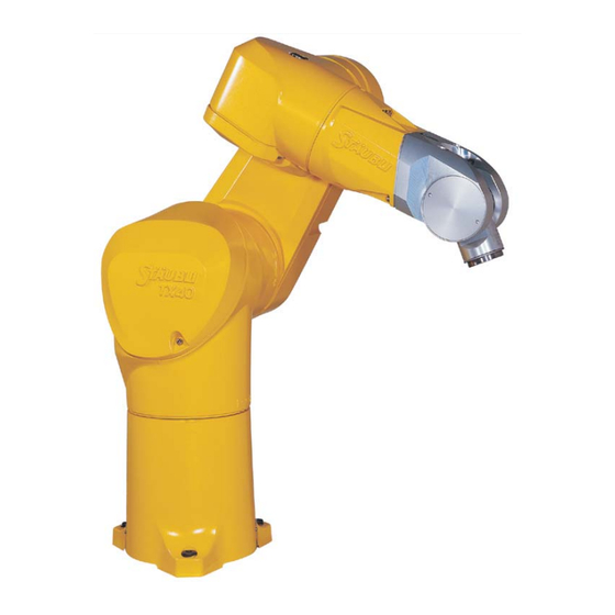
- Page 1 Arm - TX series 40 family Instruction manual D28065504A - 02/2007...
- Page 2 D28065504A - 02/2007...
-
Page 3: Table Of Contents
2 - DESCRIPTION ..................19 2.1. IDENTIFICATION........................21 2.2. GENERAL PRESENTATION ....................21 2.3. DESIGNATION OF ROBOTS OF THE TX SERIES 40 FAMILY ..........25 2.4. GENERAL CHARACTERISTICS.................... 27 2.4.1. Dimensions........................2.4.2. Work environment ....................... 27 2.4.3. Weight ......................... 27 2.5. - Page 4 D28065504A - 02/2007...
- Page 5 2.9. PRESSURIZATION SYSTEM FOR DUSTY SURROUNDINGS OR SPATTERING WITH LIQUIDS ..........................57 2.9.1. Purpose ........................57 2.9.2. Installation ........................57 2.10. RELEASING JOINT BRAKE ....................58 2.11. SAFETY ..........................58 2.12. JOINT DISPLACEMENT LIMITERS ..................59 3 - ON-SITE PREPARATION..............61 3.1.
- Page 6 D28065504A - 02/2007...
-
Page 7: Introduction
Chapter 1 – Introduction CHAPTER 1 – INTRODUCTION D28065504A - 02/2007... - Page 8 D28065504A - 02/2007...
-
Page 9: Foreword
Chapter 1 – Introduction 1.1. FOREWORD The information contained in the present document is the property of STÄUBLI and it cannot be reproduced, in full or in part, without our prior written approval. The specifications contained in the present document can be modified without notice. Although all necessary precautions have been taken to ensure that the information contained in this document is correct, STÄUBLI cannot be held responsible for any errors or omissions found in the illustrations, drawings and specifications contained in the said document. -
Page 10: Definition Of The Elements Around The Robot Cell
Notes Paragraphs of the "note" type provide very important information to help the reader to understand a description or a procedure. Note: Supplies further information, or underlines a point or an important procedure. This information must be memorized to make it easier to apply and ensure correct sequencing of the operations described. -
Page 11: Safety
Chapter 1 – Introduction 1.3. SAFETY 1.3.1. REMINDER CONCERNING THE SAFETY STANDARDS DANGER: The robot is a fast moving machine. These movements can be dangerous. Always comply with the safety standards recommended for robot use and inform operators about the dangers faced. The robot is a sub-assembly designed for integration in a robot cell. -
Page 12: Safety Directives Concerning To The Work Environment
1.3.2. SAFETY DIRECTIVES CONCERNING TO THE WORK ENVIRONMENT Analysis of safety around the robot cell Safety must be taken into account for the robot cell from the design and development stage on. Before planning the installation of the robot cell, it is necessary to study the following points: •... - Page 13 Chapter 1 – Introduction Rules concerning the robot's work area The controlled area or isolation area in which the robot moves must be determined using protective devices (protective elements). Note: Protective elements are devices protecting persons from a dangerous area. See the standards currently in force concerning safety for industrial handling equipment.
-
Page 14: Safety Directives Concerning To Staff Protection
1.3.3. SAFETY DIRECTIVES CONCERNING TO STAFF PROTECTION STÄUBLI robots work with computer controlled mechanisms, capable of moving at high speed and exerting considerable force. Like all robots and most industrial equipment, they must be controlled with great care by the user of the robot cell. All staff using STÄUBLI robots must be familiar with the warnings and recommendations given in this manual. - Page 15 Chapter 1 – Introduction Robot cell safety devices The safety devices must form an integral part of the design and installation of the robot cell. Operator training and compliance with the operating procedures constitute a major element in setting up the safety devices and systems.
-
Page 16: Safety Directives Concerning To Protection Of The Equipment
1.3.4. SAFETY DIRECTIVES CONCERNING TO PROTECTION OF THE EQUIPMENT 1.3.4.1. CONNECTIONS • Before connecting the controller to the power supply, make sure that its nominal voltage does indeed correspond to the network voltage. • When connecting the controller, use a cable whose cross-section corresponds to the power rating shown on the manufacturer's plate. - Page 17 Chapter 1 – Introduction Risks created by an electrostatic discharge A high ESD voltage (several thousand volts) creates danger for electronic components. A semi-conductor must be handled carefully to prevent destruction by ESD. ESD are truly dangerous. It is estimated that they destroy only 10% of the components that they effect.
- Page 18 1.3.4.3. PREVENTION OF DAMAGE DUE TO ELECTROSTATIC DISCHARGES It is essential to guard against electrostatic discharges during an intervention concerning electronic components, sub-assemblies and complete systems. Elimination of the danger due to ESD requires a combined team effort. By complying with the following instructions, you can substantially reduce the potential damage caused by ESD and ensure long-term reliability for the robot.
-
Page 19: Description
Chapter 2 – Description CHAPTER 2 – DESCRIPTION D28065504A - 02/2007... - Page 20 Figure 2.1 D28065504A - 02/2007...
-
Page 21: Identification
Chapter 2 – Description 2.1. IDENTIFICATION Manufacturer's plate on each robot. There is a plate riveted on the controller and arm. (see figure 2.2) Standard version UL version Figure 2.2 For all requests concerning information, replacement part orders, or requests for intervention, please state the type and the serial number of the machine concerned, as set out on the manufacturer's plate. - Page 22 D28065504A - 02/2007...
- Page 23 Chapter 2 – Description Figure 2.3 Standard arm - Rear cable outlet D28065504A - 02/2007...
- Page 24 Figure 2.4 Standard arm - Vertical cable outlet D28065504A - 02/2007...
-
Page 25: Designation Of Robots Of The Tx Series 40 Family
Chapter 2 – Description 2.3. DESIGNATION OF ROBOTS OF THE TX SERIES 40 FAMILY TX family arm Maximum working radius between joint 1 and joint 5, expressed in decimeters and rounded off to one significant digit: dimension + dimension Number of active joints: •... - Page 26 D28065504A - 02/2007...
-
Page 27: General Characteristics
Chapter 2 – Description 2.4. GENERAL CHARACTERISTICS 2.4.1. DIMENSIONS See figure 2.3. 2.4.2. WORK ENVIRONMENT • Working temperature: + 5°C to + 40°C (in accordance with standard directive NF EN 60 204 CAUTION: It may be necessary to perform a warm-up cycle before nominal performances are obtained. - Page 28 Figure 2.5 D28065504A - 02/2007...
-
Page 29: Performance
Chapter 2 – Description 2.5. PERFORMANCE See figure 2.5 Brake release access area Standard arm Work envelope R.M max. reach between axis 1 and 5 450 mm R.m1 min. reach between axis 1 and 5 151 mm R.m2 min. reach between axis 2 and 5 162 mm R.b reach between axis 3 and 5 225 mm... - Page 30 VIEW ALONG G SECTIONAL VIEW : A-A SCALE : 1:1 DETAIL : D DETAIL : C SCALE : 2:1 SCALE : 2:1 Figure 2.6 D28065504A - 02/2007...
-
Page 31: Load Capacity - Mechanical Interface
Chapter 2 – Description 2.6. LOAD CAPACITY – MECHANICAL INTERFACE See figure 2.6. Terminal (2) is not supplied with the arm assembly; its design depends on the robot’s specific applications. All studies can be undertaken in cooperation with STÄUBLI to obtain optimum performance without exceeding the robot arm assembly load limits. - Page 32 D28065504A - 02/2007...
-
Page 33: Load Capacity
Chapter 2 – Description 2.6.1. LOAD CAPACITY (figure 2.6,2.7) Load characteristics: Load center of gravity position : z = 135 mm with respect to joint 5 and x = 30 mm with respect to joint 6. Load capacity Standard arm 3.75 At nominal speed 4.41... - Page 34 VIEW ALONG : G SECTIONAL VIEW : B-B Figure 2.8 D28065504A - 02/2007...
-
Page 35: Torque Limits
Chapter 2 – Description 2.6.2. TORQUE LIMITS Reference axis Axis 1 Axis 1 (floor (wall Axis 2 Axis 3 Axis 4 Axis 5 Axis 6 moun- moun- ting) ting) Static torque (Nm) If axis 6 torque = 0 For maximum torque on axis 6 Note: These pairs are available for a load carried equal to 0 Kg. - Page 36 D28065504A - 02/2007...
- Page 37 Chapter 2 – Description J1203 J1202 J1201 Figure 2.9 Arm - Rear cable outlet D28065504A - 02/2007...
- Page 38 J1203 J1202 J1204 J1201 Figure 2.10 Arm - Vertical cable outlet D28065504A - 02/2007...
-
Page 39: User Circuit
Chapter 2 – Description 2.7. USER CIRCUIT See figure 2.9.: Arm - Rear cable outlet See figure 2.10.: Arm - Vertical cable outlet The arm cabling system is made up of a harness containing several electrical cables used to power the servomotors (power, brakes, coders), the distributors, and the login user socket. - Page 40 D28065504A - 02/2007...
- Page 41 Chapter 2 – Description 2 , 5 x 4 2 , 5 x 4 2 , 5 x 4 SECTIONAL VIEW I-I 1 3 . 3 1 3 . 3 SECTIONAL VIEW K-K 5 . 5 1 7 . 5 1 7 .
- Page 42 Sectional view I - I VIEW F 0.6 MPa / 87 PSI Sectional view K - K 0.002 MPa / 0.29 PSI Figure 2.12 Arm - Vertical cable outlet D28065504A - 02/2007...
-
Page 43: Pneumatic And Electric Systems
Chapter 2 – Description 2.8. PNEUMATIC AND ELECTRIC SYSTEMS 2.8.1. STANDARD PNEUMATIC SYSTEM (STANDARD ROBOT EQUIPMENT) Plate attached to base Forearm Description (figure 2.11): Arm - Rear cable outlet Description (figure 2.12): Arm - Vertical cable outlet • The arm is connected to the compressed air network (6 bar (87 psi) maximum, with or without lubrication) through its base (P1 and P2). - Page 44 D28065504A - 02/2007...
- Page 45 Chapter 2 – Description 2 , 5 x 4 E V 1 2 , 5 x 4 2 , 5 x 4 2 , 5 x 4 2 , 5 x 4 SECTIONAL VIEW I-I 1 3 . 3 1 3 . 3 SECTIONAL VIEW K-K G 1 / 8 5 .
- Page 46 Sectional view I - I VIEW F 0.6 MPa / 87 PSI Sectional view K - K 0.002 MPa / 0.29 PSI Figure 2.14 Arm - Vertical cable outlet D28065504A - 02/2007...
-
Page 47: Pneumatic System With Electric Distributor For Use With Compressed Air (Option)
Chapter 2 – Description 2.8.2. PNEUMATIC SYSTEM WITH ELECTRIC DISTRIBUTOR FOR USE WITH COMPRESSED AIR (OPTION) Plate attached to base Forearm Description (figure 2.13): Arm - Rear cable outlet Description (figure 2.14): Arm - Vertical cable outlet Electric distributor (EV1). •... - Page 48 D28065504A - 02/2007...
- Page 49 Chapter 2 – Description 2 , 5 x 4 E V 1 2 , 5 x 4 2 , 5 x 4 2 , 5 x 4 SECTIONAL VIEW I-I 1 3 . 3 1 3 . 3 SECTIONAL VIEW K- G 1 / 8 5 .
- Page 50 Sectional view I - I VIEW F 0.6 MPa / 87 PSI Sectional view K - K 0.002 MPa / 0.29 PSI Figure 2.16 Arm - Vertical cable outlet D28065504A - 02/2007...
-
Page 51: Pneumatic System With Electric Distributor For Use With Vacuum (Option)
Chapter 2 – Description 2.8.3. PNEUMATIC SYSTEM WITH ELECTRIC DISTRIBUTOR FOR USE WITH VACUUM (OPTION) Plate attached to base Forearm Description (figure 2.15): Arm - Rear cable outlet Description (figure 2.16): Arm - Vertical cable outlet Electric distributor (EV1). • 3/2-way monostable. •... - Page 52 D28065504A - 02/2007...
- Page 53 Chapter 2 – Description J 1 2 0 3 J 1 2 0 2 1 x ( 3 X 0 , 5 0 m m 2 ) 2 x ( 2 X 0 , 2 1 m m 2 ) W H o u B U W H o u B U Figure 2.17...
- Page 54 VIEW F 0.6 MPa / 87 PSI 0.002 MPa / 0.29 PSI Figure 2.18 Arm - Vertical cable outlet D28065504A - 02/2007...
-
Page 55: Electric Circuit
Chapter 2 – Description 2.8.4. ELECTRIC CIRCUIT Plate attached to base Elbow Description (figure 2.17): Arm - Rear cable outlet Description (figure 2.18): Arm - Vertical cable outlet The electrical circuit consists of: • A male 8-contact socket at the bottom of the arm. •... - Page 56 Figure 2.19 D28065504A - 02/2007...
-
Page 57: Pressurization System For Dusty Surroundings Or Spattering With Liquids
Chapter 2 – Description 2.9. PRESSURIZATION SYSTEM FOR DUSTY SURROUNDINGS OR SPATTERING WITH LIQUIDS 2.9.1. PURPOSE For very severe applications in dusty surroundings or with spattered liquids, the objective is to keep the pressure inside the arm above atmospheric pressure in order to avoid migration of dust and liquids. CAUTION: The overpressure must never exceed 20 mbar (0.28 psi). -
Page 58: Releasing Joint Brake
2.10. RELEASING JOINT BRAKE CAUTION: Make sure that the arm and load relevant to this joint are suitably supported. The controller must be connected to the power supply. Place the brake release selector in position corresponding to the joint to be released. When the pushbutton is pressed to free the brakes, the brake on the joint under consideration is freed and the motor is put into short-circuit on the amplifier to reduce the arm drop speed. -
Page 59: Joint Displacement Limiters
The mechanical joint displacement limiters are never reached during normal use of the robot (software joint displacement limiters and electric limiters). Nonetheless, if the equipment comes up against mechanical limiters, the fixed and moving parts must be replaced (consult the Staubli services). D28065504A - 02/2007... - Page 60 D28065504A - 02/2007...
-
Page 61: On-Site Preparation
Chapter 3 – On-site preparation CHAPTER 3 – ON-SITE PREPARATION D28065504A - 02/2007... - Page 62 D28065504A - 02/2007...
- Page 63 Chapter 3 – On-site preparation VIEW ALONG : H SCALE : 1:2 BASE ONLY SECTIONAL VIEW : E-E SCALE : 1:2 Figure 3.1 Arm - Rear cable outlet D28065504A - 02/2007...
- Page 64 Sectional view B - B (*) opening to put connections and screws through Sectional view A - A O-ring housing : interior O-ring diam eter : 1 9 7 torus diam eter : 5 . 3 3 Figure 3.2 Arm - Vertical cable outlet D28065504A - 02/2007...
-
Page 65: Working Space
Chapter 3 – On-site preparation 3.1. WORKING SPACE The user is responsible for performing all preparatory work required to complete the on-site installation of the robot. Working space must be sufficient, installation surface appropriate; the power supplies must be available (for the electric power supplies, see the characteristics of the controller). CAUTION: To enable all maintenance operations to be carried out, it is essential to provide easy access to the robot (e.g. - Page 66 Under following load conditions: Load position (mm) Load (kg) Axis 5 Axis 6 inch inch 3.75 5.31 1.18 Standard arm The user can accurately position the robot by means of two 8h8 diameter centering pins (not supplied). D28065504A - 02/2007...
-
Page 67: Storage, Transport And Installation
Chapter 4 – Storage, transport and installation CHAPTER 4 – STORAGE, TRANSPORT AND INSTALLATION D28065504A - 02/2007... -
Page 68: Arm Packaging
4.1. ARM PACKAGING Packaging position of the arm: Axis 1 Axis 2 Axis 3 Axis 4 Axis 5 Axis 6 0° +93° +87° 0° 0° 0° Angular position Standard packaging: Standard arm 900 x 640 x 570 mm Case L x H x D (35.4 x 25.2 x 22.4 in) 40 kg (88.2 lb) Gross weight... -
Page 69: Installation Of Arm
Chapter 4 – Storage, transport and installation 4.4. INSTALLATION OF ARM CAUTION: The arm can be fixed with its base facing downwards (floor-mounted version), upwards (ceiling-mounted version), or against a wall, without requiring any mechanical modifications. However, it is necessary to configure the controller accordingly. To do so, see the "Software configuration"... - Page 70 D28065504A - 02/2007...
-
Page 71: Preventive Maintenance
Chapter 5 – Preventive maintenance CHAPTER 5 – PREVENTIVE MAINTENANCE D28065504A - 02/2007... - Page 72 D28065504A - 02/2007...
-
Page 73: Defining The Levels Of Intervention
Chapter 5 – Preventive maintenance 5.1. DEFINING THE LEVELS OF INTERVENTION Level 1: Operations that can be carried out by a maintenance technician without specific STÄUBLI training. • Replacement of the cover seals (see chapter 5.2) • Checking oil levels (see chapter 5.4) •... -
Page 74: Procedure For Replacing The Flat Seal
To keep the performance of the arm at an optimal level the arm requires preventive maintenance. The maintenance operations must be carried out by persons who have followed the appropriate course given by STÄUBLI. CAUTION: To ensure a correct seal, it is essential to replace the seal each time a cover is removed. 5.2. -
Page 75: Maintenance Frequency
Chapter 5 – Preventive maintenance 5.3. MAINTENANCE FREQUENCY Every year: • Check the general condition of the arm. • Check the oil level for each seal. • Check the condition of the harness (visible parts). After 20 000 h: • Consult STÄUBLI to define a preventive maintenance programme adapted to the use you make of the arm. - Page 76 Figure 5.1 D28065504A - 02/2007...
-
Page 77: Checking Oil Levels
Chapter 5 – Preventive maintenance 5.4. CHECKING OIL LEVELS 5.4.1. ARM IN FLOOR-MOUNTED POSITION (figure 5.1) 5.4.1.1. SOFTWARE ANGULAR POSITION OF JOINTS FOR CHECKING LEVELS Position Joint 1 Joint 2 Joint 3 Joint 4 Joint 5 0° 0° 0° 0° 0°... - Page 78 Figure 5.2 D28065504A - 02/2007...
-
Page 79: Arm In Ceiling-Mounted Position
Chapter 5 – Preventive maintenance 5.4.2. ARM IN CEILING-MOUNTED POSITION (figure 5.2) 5.4.2.1. SOFTWARE ANGULAR POSITION OF JOINTS FOR CHECKING LEVELS. Position Joint 1 Joint 2 Joint 3 Joint 4 Joint 5 Joint 1 0° 0° 0° 0° 0° Joint 2 0°... - Page 80 D28065504A - 02/2007...
-
Page 81: Recommended Spare Parts
Chapter 6 – Recommended spare parts CHAPTER 6 – RECOMMENDED SPARE PARTS D28065504A - 02/2007... - Page 82 D28065504A - 02/2007...
- Page 83 Chapter 6 – Recommended spare parts • Solenoid valve. • MOBIL SHC 626 oil*. • MOBIL SHC 639 oil*. • Cover seal kit. *Maximum oil quantity: • Axis 1: SHC 626 300 cm • Axis 2: SHC 626 90 cm •...
- Page 84 D28065504A - 02/2007...
Need help?
Do you have a question about the TX Series and is the answer not in the manual?
Questions and answers