
Related Manuals for Rohde & Schwarz SML01


Summary of Contents for Rohde & Schwarz SML01
- Page 1 Operating Manual SIGNAL GENERATOR R&S SML01 R&S SMV03 1090.3000.11 1047.7509.13 R&S SML02 1090.3000.12 R&S SML03 1090.3000.13 Printed in Germany Test and Measurement Division 1171.5490.12-01-...
- Page 2 Dear Customer, hroughout this manual, R&S® SML and R&S® SMV03 are abbreviated as R&S SML and R&S SMV03. R&S® is a registered trademark of Rohde & Schwarz GmbH & Co. KG. Trade names are trademarks of the owners.
- Page 3 R&S®SML / R&S®SMV03 Tabbed Divider Overview Tabbed Divider Overview Contents Index Data Sheet Safety Instructions Certificate of Quality EC Certificate of Conformity List of R&S Representatives Short Tutorial About How to Use the Manual Divider Chapter 1 Preparation for Use Chapter 2 Introduction to Operation Chapter 3...
-
Page 5: Table Of Contents
R&S®SML / R&S®SMV03 Contents Contents 1 Putting into Operation ..................1.1 General Instructions ........................1.1 Unpacking the Instrument ......................1.1 Setting up the Instrument ......................1.2 Cleaning the Outside and Storing ....................1.2 Supply Voltage..........................1.3 How to Ensure EMC ........................1.3 Power Fuses ..........................1.3 Switching On/Off the Instrument ....................1.3 Initial Status ..........................1.3 RAM With Battery Back-Up......................1.4 Preset Setting ..........................1.4... - Page 6 Contents R&S®SML / R&S®SMV03 4 Instrument Functions..................4.1 RF Frequency..........................4.1 Frequency Offset........................4.2 Extended Divider Range ......................4.2 RF Level............................4.3 Level Offset ..........................4.5 Non-Interrupting Level Setting....................4.5 Switching On/Off Automatic Level Control (ALC)..............4.6 User Correction (Ucor) ......................4.7 [RF ON/OFF] Key........................4.8 Modulation - General........................4.9 Modulation Sources........................4.9 Simultaneous Modulation .......................4.10 Mutual Switch-Off of Modulation Types..................4.10...
- Page 7 R&S®SML / R&S®SMV03 Contents Display of Service Data (Diag - Param) .................4.65 Test ............................4.66 Assigning Modulations to the [MOD ON/OFF] Key (ModKey)..........4.67 Setting the Sweep Blank Time ....................4.68 Status............................4.69 5 Remote Control – Basic Information ..............5.1 Brief Instructions.........................5.1 IEC/IEEE Bus ...........................5.1 RS-232-C Interface ........................5.2 Switchover to Remote Control....................5.3 Remote Control via IEC/IEEE Bus ...................5.3...
- Page 8 Contents R&S®SML / R&S®SMV03 6 Remote Control – Description of Commands........... 6.1 Notation ............................6.1 Common Commands ........................6.3 ABORt System ..........................6.6 CALibration System ........................6.6 DIAGnostic System ........................6.8 DISPLAY System ........................6.10 MEMory System.........................6.11 OUTPut System .........................6.11 SOURce System ........................6.13 SOURce:AM Subsystem ......................6.13 SOURce:CORRection Subsystem ..................6.15 SOURce:DM Subsystem (R&S SMV03) ................6.17 SOURce:FM Subsystem ......................6.19...
- Page 9 R&S®SML / R&S®SMV03 Contents 7 Remote Control - Programming Examples ............7.1 Including IEC-Bus Library for QuickBasic................7.1 Initialization and Default Status ....................7.1 Initiate Controller ........................7.1 Initiate Instrument........................7.1 Transmission of Instrument Setting Commands ..............7.2 Switchover to Manual Control ....................7.2 Reading out Instrument Settings....................7.2 Command synchronization ......................7.3 Service Request...........................7.4 8 Maintenance ......................
- Page 10 Contents R&S®SML / R&S®SMV03 10 Performance Test....................10.1 General ............................10.1 Measuring equipment and accessories ..................10.2 Test setups ..........................10.3 Standard test setup ........................10.3 Test setup for setting time .......................10.3 Test setup for SSB phase noise.....................10.4 Test setup for output reflection coefficient ................10.4 Test setup for pulse modulator option R&S SML-B3 .............10.5 Test setup for stereo coder option R&S SML-B5 ..............10.5 Test sequence ...........................10.6...
- Page 11 R&S®SML / R&S®SMV03 Contents Tables Table 4-1 Overview of internal calibration routines ..............4.62 Table 5-1 Synchronization by means of *OPC, *OPC? and *WAI ..........5.15 Table 5-2 Meaning of the bits used in the status byte..............5.19 Table 5-3 Meaning of the bits used in the event status register...........
- Page 12 Contents R&S®SML / R&S®SMV03 Figures Fig. 1-1 Front panel view......................1.5 Fig. 1-2 Rear panel view ......................1.10 Fig. 1-2 Rear panel view ......................1.11 Fig. 2-1 Display for AM setting ....................2.3 Fig. 2-2 Display for pattern setting ....................2.5 Fig. 3-1 Design of the display......................3.1 Fig.
- Page 13 R&S®SML / R&S®SMV03 Contents Fig. 4-26 Utilities – System – RS232 menu.................4.57 Fig. 4-27 Utilities – System – Security menu................4.58 Fig. 4-28 Utilities – RefOsc menu (preset setting) ..............4.59 Fig. 4-29 Menu Utilities – Phase ....................4.60 Fig. 4-30 Utilities - Protect menu (preset setting)................4.61 Fig.
- Page 15 R&S®SML / R&S®SMV03 Index Index recognition ..............5.14 sequence ..............5.15 setting commands............5.5 Abort actions triggered............6.6 short form..............5.7 Active edge ............. 4.18, 4.48, 6.52 structure ................5.6 Address structure of command lines...........5.9 IEC/IEEE bus ............5.3, 6.47 synchronization ............5.15, 7.3 Addressed commands ............5.27 syntax elements............5.12 universal commands ...........5.27 coupling .............
- Page 16 Index R&S®SML / R&S®SMV03 Edge Gate signal external trigger............6.52 trigger............4.18, 4.22, 4.48 Edit GET (Group Execute Trigger) ...........5.14 list ................. 3.9 list entry ..............3.12 EMC..................1.3 ENABle part ..............5.17 Envelope ................4.17 EOI (command line) ............5.9 EPROM, test..............
- Page 17 R&S®SML / R&S®SMV03 Index store ................3.14 dwell time ............4.53, 6.40 Interface start level............4.53, 6.29 functions (IEC/IEEE bus) ........... 5.26 step width............4.53, 6.41 functions (RS-232-C)..........5.29 stop level............4.53, 6.29 IEC/IEEE bus ............ 1.11, 5.25 sweep mode..........4.53, 6.28, 6.40 messages (IEC/IEEE bus) ......... 5.27 LF generator .............4.46, 6.42 RS-232-C ............
- Page 18 Index R&S®SML / R&S®SMV03 Utilities – AuxIO............4.68 Utilities - Calib............. 4.62 Utilities - Diag - Config..........4.63 Offset Utilities - Diag - Param..........4.65 frequency ..............4.1 Utilities – Diag - TPoint..........4.64 level................4.4 Utilities - Display............4.55 On/Off switch...............1.5 Utilities - ModKey ............
- Page 19 R&S®SML / R&S®SMV03 Index Pulse delay............4.17, 4.47, 6.31 period............4.17, 4.47, 6.31 Sample setting..............2.1 width ............4.17, 4.47, 6.32 Sample-and-Hold mode............4.7 Pulse generator............4.18, 6.31 Save PULSE input.............1.10, 4.18, 6.52 instrument settings............3.14 Pulse modulation ............. 4.17, 6.30 SCPI Pulse polarity ......... 4.17, 4.47, 6.12, 6.30 introduction ..............5.6 Pulse source Scrollbar ................3.2...
- Page 20 Index R&S®SML / R&S®SMV03 Suppression indication ..............4.58 Sweep Ucor (level correction) ..........4.9, 6.15 inputs................4.51 Universal commands............5.27 level sweep............4.53, 6.27 Unlock LF sweep............4.54, 6.44 calibration..............4.61 operating modes............4.50 Unpacking................1.1 RF sweep ..........4.51, 6.22, 6.39 User correction (Ucor) ..........4.9, 6.15 trigger .................
- Page 21 R&S SML01/02/03, R&S SMV03 standard specification Level frequency response same as R&S SML01/02/03, R&S SMV03 standard specification same as R&S SML01: f < 1 MHz: <0.7 dB Output impedance 50 8 Output matching R&S SML01: level > 10 dBm;...
- Page 23 Before putting the product into operation for the first time, make sure to read the following S a f e t y I n s t r u c t i o n s All plants and locations of the Rohde & Schwarz group of companies make every effort to keep the safety standard of our products up to date and to offer our customers the highest possible degree of safety.
- Page 24 Safety Instructions Observing the safety instructions will help prevent personal injury or damage of any kind caused by dangerous situations. Therefore, carefully read through and adhere to the following safety instructions before putting the product into operation. It is also absolutely essential to observe the additional safety instructions on personal safety that appear in relevant parts of the product documentation.
- Page 25 Safety Instructions 4. If products/components are mechanically product itself is not permitted. Doing so can and/or thermically processed in a manner result in the danger of an electric shock that goes beyond their intended use, from the product. If extension cords or hazardous substances (heavy-metal dust connector strips are implemented, they such as lead, beryllium, nickel) may be...
- Page 26 Safety Instructions 19. If a product is to be permanently installed, the battery or storage battery only with the the connection between the PE terminal on matching Rohde & Schwarz type (see site and the product's PE conductor must spare parts list). Batteries and storage be made first before any other connection batteries must be recycled and kept is made.
- Page 27 Informaciones de seguridad Por favor lea imprescindiblemente antes de la primera puesta en funcionamiento las siguientes Informaciones de seguridad El principio del grupo de empresas Rohde & Schwarz consiste en tener nuestros productos siempre al día con los estandards de seguridad y de ofrecer a nuestros clientes el máximo grado de seguridad. Nuestros productos y todos los equipos adicionales son siempre fabricados y examinados según las normas de seguridad vigentes.
- Page 28 Informaciones de seguridad Tener en cuenta las informaciones de seguridad sirve para tratar de evitar daños y peligros de toda clase. Es necesario de que se lean las siguientes informaciones de seguridad concienzudamente y se tengan en cuenta debidamente antes de la puesta en funcionamiento del producto. También deberán ser tenidas en cuenta las informaciones para la protección de personas que encontrarán en el capítulo correspondiente de la documentación de producto y que también son obligatorias de seguir.
- Page 29 Informaciones de seguridad 3. Como en todo producto de fabricación comprometido a valorar y señalar areas de industrial no puede ser excluido en general trabajo en las que se corra un riesgo de que se produzcan al usarlo elementos aumentado de exposición a radiaciones para que puedan generar alergias, los llamados evitar riesgos.
- Page 30 Informaciones de seguridad 12. No utilice nunca el producto si está dañado el 20. En caso de que los productos que son cable eléctrico. Compruebe regularmente el instalados fijamente en un lugar sean sin correcto estado de los cables de conexión a protector implementado, autointerruptor o red.
- Page 31 Informaciones de seguridad 27. Baterías y acumuladores no deben de ser 31. Las asas instaladas en los productos sirven expuestos a temperaturas altas o al fuego. solamente de ayuda para el manejo que Guardar baterías y acumuladores fuera del solamente está previsto para personas. Por alcance de los niños.
- Page 33 Certified Quality System DIN EN ISO 9001 : 2000 DIN EN 9100 : 2003 DIN EN ISO 14001 : 2004 DQS REG. NO 001954 QM UM QUALITÄTSZERTIFIKAT CERTIFICATE OF QUALITY CERTIFICAT DE QUALITÉ Sehr geehrter Kunde, Dear Customer, Cher Client, Sie haben sich für den Kauf eines you have decided to buy a Rohde &...
- Page 35 EC Certificate of Conformity Certificate No.: 99059 This is to certify that: Equipment type Stock No. Designation SML01 1090.3000.11 Signal Generator 9 kHz to 1.1 GHz SML02 1090.3000.12 Signal Generator 9 kHz to 2.2 GHz SML03 1090.3000.13 Signal Generator 9 kHz to 3.3 GHz SML-B1 1090.5790.02...
- Page 37 EC Certificate of Conformity Certificate No.: 2001-56 This is to certify that: Equipment type Stock No. Designation SMV03 1147.7509.13 Vector Signal Generator 9 kHz to 3.3 GHz SML-B1 1090.5790.02 Reference Oscillator SML-B3 1090.5403.02 Pulse Modulator SML-B5 1147.8805.02 Stereo/RDS Coder complies with the provisions of the Directive of the Council of the European Union on the approximation of the laws of the Member States - relating to electrical equipment for use within defined voltage limits (73/23/EEC revised by 93/68/EEC)
- Page 39 Customer Support Technical support – where and when you need it For quick, expert help with any Rohde & Schwarz equipment, contact one of our Customer Support Centers. A team of highly qualified engineers provides telephone support and will work with you to find a solution to your query on any aspect of the operation, programming or applications of Rohde &...
- Page 41 Address List Headquarters, Plants and Subsidiaries Locations Worldwide Headquarters Please refer to our homepage: www.rohde-schwarz.com ◆ ROHDE&SCHWARZ GmbH & Co. KG Phone +49 (89) 41 29-0 Sales Locations Mühldorfstraße 15 · D-81671 München Fax +49 (89) 41 29-121 64 ◆ Service Locations P.O.Box 80 14 69 ·...
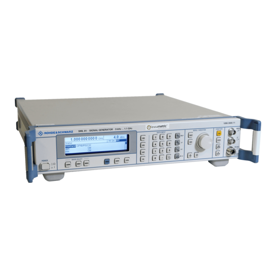
- Page 43 Signal Generator R&S SML / R&S SMV03 and also contains specifications of the instrument and available options. The following models are described in this manual: R&S SML01 9 kHz to 1.1 GHz R&S SML02 9 kHz to 2.2 GHz...
-
Page 45: Putting Into Operation
R&S®SML / R&S®SMV03 Putting into Operation Putting into Operation This chapter contains all information about putting into operation (unpacking, connection to AC supply, switching on and off), functional testing and installation of the instrument, preset settings and views of the front and rear panel showing the controls and connectors needed for operation. General Instructions Before putting the R&S SML / R&S SMV03 into operation, please make sure that •... -
Page 46: Setting Up The Instrument
Putting into Operation R&S SML / R&S SMV03 Setting up the Instrument For applications in the laboratory or on a work bench, it is recommended that the support feet on the bottom of the instrument be extended. For the LCD display, this provides the optimum viewing angle which typically ranges from perpendicular to the display front to approximately 30°... -
Page 47: Supply Voltage
R&S®SML / R&S®SMV03 Putting into Operation Supply Voltage The R&S SML / R&S SMV03 can be operated at a.c. systems from 100 to 120 V and 200 to 240 V at system frequencies from 50 to 60 Hz. The power supply socket is situated at the rear of the instrument. The instrument automatically sets itself to the voltage applied within the permissible voltage ranges. -
Page 48: Ram With Battery Back
Putting into Operation R&S SML / R&S SMV03 RAM With Battery Back-Up The R&S SML / R&S SMV03 has a static read-write memory (CMOS-RAM) with battery back-up, in which 50 different complete settings of the instrument can be stored (cf. Chapter 3, section "Storing and Calling of Instrument Settings"). -
Page 49: Explanation Of Front And Rear Panel
R&S®SML / R&S®SMV03 Front Panel Explanation of Front and Rear Panel Elements of the Front Panel ON/OFF SWITCH The On/Off switch switches the instrument on ("I") or off ("O"). Cf. Chapter 1, Section "Switching On/Off the Instrument". DISPLAY Cf. Chapter 3 for the design of the display. Parameter field Parameters RF frequency and RF level can be entered directly by means of the parameter keys, alternatively to... - Page 50 Front panel R&S®SML / R&S®SMV03 DATA INPUT Numeric input field Numeric values, decimal point and minus sign can be entered by means of the digital keys. 0 to 9 Enters the digit. Enters the decimal point. Enters the minus sign. Deletes the last input (digit, sign or decimal point) - key [BACKSPACE].
- Page 51 R&S®SML / R&S®SMV03 Front Panel MENU/VARIATION Menu keys The menu keys access the menus and settings within the menus. SELECT Acknowledges the choice marked by the menu cursor. BACK Returns the menu cursor to the next higher menu level. Moves the digit cursor to the left by one position in the marked value indication.
- Page 52 Front panel R&S®SML / R&S®SMV03 FUNCTION HELP* Indicates context-sensitive auxiliary text. STATUS* Indicates the instrument status. ON/OFF Switches on/off the modulation selected in Utilities - ModKey. ON/OFF Switches on/off the RF signal. Cf. Chapter 4, Sections "The Help System", "Status", and Chapter 3, Section "Use of [MOD ON/OFF] and [RF ON/OFF] keys".
- Page 53 R&S®SML / R&S®SMV03 Front Panel QUICK SELECT The menu-quick-selection keys permit fast access to two menus selected. ASSIGN Stores the current menu as menu1 when the MENU1 key is pressed afterwards or as menu2 when the MENU2 key is pressed afterwards.
-
Page 54: Elements Of The Rear Panel
Rear Panel R&S®SML / R&S®SMV03 Elements of the Rear Panel RF 50 Relocation of MOD input for external modulation signals. Only with option R&S SML-B19. Relocation of LF output for signals of internal LF generator. Only with option R&S SML-B19. RF 50 M Relocation of output for RF signals. -
Page 55: Fig. 1-2 Rear Panel View
R&S®SML / R&S®SMV03 Rear Panel IEEE 488 SCPI IEC 625 IEC-bus (IEEE 488) IEEE 488 Interface for Remote Control Cf. Chapter 5 "Remote Control". Power supply connector and fuse holder Cf. Chapter 1, Section “Power Fuses”. R&S SMV03 only I, Q Relocation of the inputs for external modulation signals forI/Q modulation. -
Page 57: Short Tutorial
R&S®SML / R&S®SMV03 Sample Setting for First Users Short Tutorial The present chapter contains a short tutorial with sample settings allowing the users to operate immediately the instrument. Sample Setting for First Users Setting frequency and level of the RF output signal First frequency and level of the RF output signal are set via keys [FREQ] and [LEVEL] in the DATA INPUT field: - Frequency... - Page 58 Sample Setting for First Users R&S®SML / R&S®SMV03 AM modulation of the output signal The output signal is to be amplitude-modulated next. - AM modulation depth 10.5 % - AM signal 3-kHz sine Operating steps Explanations MENU / VARIATION MENU / VARIATION Select menu Modulation using rotary knob.
-
Page 59: Fig. 2-1 Display For Am Setting
R&S®SML / R&S®SMV03 Sample Setting for First Users Operating steps Explanations MENU / VARIATION MENU / VARIATION Select LF generator as modulation source using rotary knob. The selection mark marks LFGen. LFGen SELECT Press [BACK] key. The cursor is set BACK back to AM Source. - Page 60 Sample Setting for First Users R&S®SML / R&S®SMV03 Setting the step width Subsequently to the above setting, 1 GHz as new RF frequency and 12 kHz as the step width for the RF frequency variation are set in the following. Operating steps Explanations Reset the menu cursor to the main...
-
Page 61: Fig. 2-2 Display For Pattern Setting
R&S®SML / R&S®SMV03 Sample Setting for First Users Operating steps Explanations Press [BACK] key. The menu cursor is set back to Knob Step User. BACK MENU / VARIATION Select parameter Knob Step using MENU / VARIATION rotary knob. Press [SELECT] key or rotary knob. Knob Step SELECT A pop-up menu displays the available... -
Page 63: Manual Operation
R&S®SML / R&S®SMV03 Design of the Display Manual Operation This chapter shows the design of the display and describes the manual control of the signal generator, for example calling up of menus, selection and editing of parameters, use of the list editor and the SAVE/RECALL function. -
Page 64: Basic Operating Steps
Basic Operating Steps R&S®SML / R&S®SMV03 Basic Operating Steps To operate the instrument, menus are called in the display. All setting possibilities and the current setting status are evident from the menus. All settings can be made by accessing the menus. RF frequency and RF level can also be set without menu operation using keys [FREQ] and [LEVEL]. -
Page 65: Selection And Change Of Parameters
R&S®SML / R&S®SMV03 Basic Operating Steps Selection and Change of Parameters Select parameter Set the menu cursor to the name of the parameter desired using the rotary knob, e.g. to AM Depth in the AM menu, cf. Fig. 3-2. Change setting Select parameter. -
Page 66: Quick Selection Of Menu (Quick Select)
Basic Operating Steps R&S®SML / R&S®SMV03 1-out-of-n selection Select parameter. Press [SELECT] key or rotary knob. A pop-up menu displays a selection of settings. Set the menu cursor to the position desired within the 1-out-of-n selection using the rotary knob or cursor keys [ ] [ ]. Press [SELECT] key or rotary knob. -
Page 67: Use Of [Freq] And [Level] Keys
R&S®SML / R&S®SMV03 Basic Operating Steps Use of [FREQ] and [LEVEL] Keys RF frequency and RF level can be set without menu operation as well using direct keys [FREQ] and [LEVEL]. [FREQ] / [LEVEL] keys Press [FREQ] or [LEVEL] key. The frequency or the level indication in the header field of the display is marked. -
Page 68: Correction Of Input
Basic Operating Steps R&S®SML / R&S®SMV03 Correction of Input Digits can be corrected by one of the following keys before the input is confirmed by the [Enter] key: The backspace key deletes the value entered digit by digit. Key [-/ Pressing the [BACK] key deletes the entire entry and results in the previous [BACK] key value being indicated again. -
Page 69: List Editor
R&S®SML / R&S®SMV03 List Editor List Editor The R&S SML / R&S SMV03 offers the facility of generating lists for user-defined level correction (Ucor). The lists consist of elements (pairs of values) which are defined by an index and at least one parameter per index. -
Page 70: Select List
List Editor R&S®SML / R&S®SMV03 Select List Mark the desired list using the rotary knob (see Fig. 3-4). Press the [SELECT] key or the rotary knob. The selected list is included in the instrument setup. The selection window is closed. The selected list is displayed under Select List. -
Page 71: Edit List
R&S®SML / R&S®SMV03 List Editor Edit List When Edit List is selected, a pop-up menu with the editing functions opens. Insert editing function (see Fig. 3-6) The Insert function inserts a desired number of elements with constant or linearly increasing/decreasing values ahead of the element with the indicated start index. -
Page 72: Fig. 3-6 Edit Function Insert
List Editor R&S®SML / R&S®SMV03 Selection: Insert Fig. 3-6 Edit function Insert Insert At Input of start index. Number of elements to be inserted. Range Input of start value for the frequency. Start Frequency Increment Frequency Input of increment between two successive frequency values. If 0 is entered as an increment, identical values will be inserted. -
Page 73: Fig. 3-7 Fill Editing Function
R&S®SML / R&S®SMV03 List Editor Fill editing function (see Fig. 3-7) The Fill function overwrites a parameter with constant or linearly increasing/decreasing values within a defined range. If the [BACK] key is pressed, the editing window will be exited without any change being made. -
Page 74: Fig. 3-8 Edit Editing Function
List Editor R&S®SML / R&S®SMV03 Edit/View editing function (see Fig. 3-8) The Edit/View function allows viewing of a complete list or editing individual values of a list. If the cursor is on a value in the left column of the list, the Edit/View mode can be exited by pressing the [BACK] key. -
Page 75: Fig. 3-9 Delete Editing Function
R&S®SML / R&S®SMV03 List Editor Delete editing function (see Fig. 3-9) The Delete function deletes the elements of the indicated range. After a delete no gap is left in the list but the remaining elements move up. If the indicated range extends beyond the end of the list, the elements until the end of the list are deleted. -
Page 76: Storing/Calling Of Instrument Settings
Storing/Calling of Instrument Settings R&S®SML / R&S®SMV03 Storing/Calling of Instrument Settings (SAVE / RECALL) 50 complete instrument settings can be stored in memory locations 1 to 50. Operating Steps Explanations Store current instrument setting in DATA INPUT memory location 12. SAVE dB(m) ENTER... -
Page 77: Menu Summary For R&S Sml
R&S®SML / R&S®SMV03 Menu Summary for R&S SML Menu Summary for R&S SML 1090.3123.12 3.15... -
Page 78: Menu Summary For R&S Smv03
Menu Summary for R&S SMV03 R&S®SML / R&S®SMV03 Menu Summary for R&S SMV03 1090.3123.12 3.16... -
Page 79: Instrument Functions
R&S®SML / R&S®SMV03 RF Frequency Instrument Functions This chapter describes the functions of the instrument and its options which can be activated manually via menus or by remote control (frequency and level settings, analog modulations, sweep, and general functions not directly related to signal generation). RF Frequency The RF frequency can be set directly using the [FREQ] key or via the Frequency menu. -
Page 80: Fig. 4-2 Typical Setups With Frequency Offset
RF Frequency R&S®SML / R&S®SMV03 Decimal The variation step size corresponds to the position of the digit cursor. Knob Step User User-defined, the variation step size is as entered under Knob Step User. Exclude from Recall Off Normal setting. The stored frequency is loaded too when instrument settings are loaded with the [RCL] key. -
Page 81: Rf Level
R&S®SML / R&S®SMV03 RF Level RF Level The RF level can be set directly using the [LEVEL] key or via the Level - Level menu. In the Level - Level menu, the set RF output level is entered and indicated under Amplitude. In level settings made with the [LEVEL] key, the offset of a subsequent attenuator/amplifier is taken into account (see section "Level Offset"). - Page 82 RF Level R&S®SML / R&S®SMV03 Auto Normal setting. The electronically switched attenuator switches in Attenuator Mode steps of 5 dB at fixed points. IEC/IEEE-bus command :OUTP:AMOD AUTO Fixed Level settings are made without switching the attenuator (see section "Non-Interrupting Level Setting"). IEC/IEEE-bus command :OUTP:AMOD FIX Indicates the level range of non-interrupting level setting in "Attenuator Mode...
-
Page 83: Level Offset
"Level overrange" or “Unleveled” is output. Please note limit and/or other limiting factors. Table 4-1 Basic switching levels for SML01/03,SMV03 (current model of SMV03 only) w/o B10 SML01 5 dBm . 2 dBm ..(0, -5 ...) -
Page 84: Switching On/Off Automatic Level Control (Alc)
RF Level R&S®SML / R&S®SMV03 Switching On/Off Automatic Level Control (ALC) Settings for automatic level control (ALC) can be made in the Level – ALC menu. When level control is switched off (ALC State Off), switchover is made to a sample-and-hold mode. In the sample-and-hold mode, level control is switched on automatically for a short time after each level or frequency setting and the level control is held at the value attained. -
Page 85: User Correction (Ucor)
R&S®SML / R&S®SMV03 RF Level User Correction (Ucor) The "User correction" function can be used to create and activate lists in which level correction values are assigned to arbitrary RF frequencies. Up to 10 lists with a total of 160 correction values can be compiled. For frequencies not included in the list, level correction values are determined by interpolation based on the nearest correction values. -
Page 86: [Rf On/Off] Key
RF Level R&S®SML / R&S®SMV03 Menu selection: Level - UCor Fig. 4-8 UCor - Level menu UCor Indication of list item number. Available space. Free 150, for example, means that there is free space for a Free total of 150 pairs of values (elements) in the list memory. Occupied space. -
Page 87: Modulation - General
R&S®SML / R&S®SMV03 Modulation - General Modulation - General The R&S SML / R&S SMV03 offers the following modulation types : • Amplitude modulation (AM), • Frequency modulation (FM), • Phase modulation ( M), • Pulse modulation PULSE (Option R&S SML-B3), •... -
Page 88: Simultaneous Modulation
Modulation - General R&S®SML / R&S®SMV03 Extrenal modulation sources for vector modulation For external vector modulation, input connectors I and Q are available at the rear panel of the SMV03 (input impedances 50 ). To avoid the I/Q modulator being overdriven the input voltage should never exceed I = 0.5 V. -
Page 89: Analog Modulations
R&S®SML / R&S®SMV03 Amplitude Modulation Analog Modulations Amplitude Modulation Settings for amplitude modulation can be made in the Modulation - AM menu. Notes: - The specified AM data are valid only up to 6 dB below the maximum level in each case. For level values exceeding this threshold, AM data are guaranteed only with linearly decreasing modulation depth. -
Page 90: Frequency Modulation
Frequency Modulation R&S®SML / R&S®SMV03 Frequency Modulation Settings for frequency modulation can be made in the Modulation - FM menu. Menu selection: Modulation – FM Fig. 4-10 Modulation - FM menu (preset setting) Input value for deviation. FM Deviation IEC/IEEE-bus command :SOUR:FM 10kHz FM Source Switching on/off FM and selection of modulation source. -
Page 91: Phase Modulation
R&S®SML / R&S®SMV03 Phase Modulation Phase Modulation Settings for phase modulation can be made in the Modulation – M menu. Menu selection: Modulation – Fig. 4-11 Modulation - M menu (preset setting) Input value for deviation. M Deviation IEC/IEEE-bus command :SOUR:PM 1 RAD Switching on/off PM and selection of modulation source. -
Page 92: Pulse Modulation (Option R&S Sml-B3)
Pulse Modulation (Option R&S SML-B3) R&S®SML / R&S®SMV03 Pulse Modulation (Option R&S SML-B3) The pulse modulator can be controlled from an external source or by an internal pulse generator. With external control, the external source feeds the pulse modulator directly. The envelope of the RF is identical to the control signal. - Page 93 R&S®SML / R&S®SMV03 Pulse Modulation (Option R&S SML-B3) Delay between the two pulses of a double pulse. This value is indicated only Double Pulse Delay if Double Pulse State is set to On. IEC/IEEE-bus command :SOUR:PULS:DOUB:DEL 1us Double Pulse State Switching on/off double pulse.
-
Page 94: Fig. 4-13 Signal Example 1: Single Pulse, Pulse Mode = Auto Trig
Pulse Modulation (Option R&S SML-B3) R&S®SML / R&S®SMV03 Int. SYNC signal PERIOD WIDTH PULSE DELAY WIDTH PULSE DELAY VIDEO signal RF signal Fig. 4-13 Signal example 1: single pulse, Pulse mode = Auto Trig PULSE input TRIGGER DELAY Int. SYNC signal DOUBLE PULSE DELAY WIDTH WIDTH... -
Page 95: Stereo Modulation (Option R&S Sml-B5)
R&S®SML / R&S®SMV03 Stereo Modulation (Option R&S SML-B5) Stereo Modulation (Option R&S SML-B5) For stereo modulation external modulation sources or the internal LF generator can be used. For analog modulation signals, input connectors R and L are available at the rear panel. A digital stereo signal can be attached to the S/P DIF input (i. - Page 96 Stereo Modulation (Option R&S SML-B5) R&S®SML / R&S®SMV03 Selection of the modulation source. The sources cannot be used Source simultaneously. The stereo modulation is witched off. Ext L, R Selection of the L and R inputs for external analog modulation signals. Ext S/P DIF Selection of the S/P DIF input for the external digital modulation signal.
- Page 97 R&S®SML / R&S®SMV03 Stereo Modulation (Option R&S SML-B5) Switching on/off the ARI subcarrier.. ARI State ARI subcarrier switched on ARI subcarrier switched off IEC/IEEE-bus command :SOUR:STER:ARI:STAT ON ARI Deviation Input value of the frequency deviation of the ARI subcarrier. IEC/IEEE-bus command :SOUR:STER:ARI:DEV 3.5kHz ARI Idendification Selection between ARI broadcasting code (DK) and traffic area code (Bk).
- Page 98 Stereo Modulation (Option R&S SML-B5) R&S®SML / R&S®SMV03 Indication of the program service name of the selected RDS data set Program Service Name (hexadecimal value OOOO bisFFFF). Each RDS data set has its own program service name. It can only be modified over the IEC/IEEC bus or the RS-232 interface (see section "RDS commands").
- Page 99 R&S®SML / R&S®SMV03 Stereo Modulation (Option R&S SML-B5) Commands for the Stereo/RDS Coder Option SML-B5 Commands are sent to the Stereo/RDS Coderwith STEReo:DIRect: ["command string" Information is queried with STEReo:DIRect? ["Befehls-String"]. All commands are to be terminated with CR. Uppercase and lowercase letters are used to identify the long form and short form of the keywords of the commands given in the manual.
- Page 100 Stereo Modulation (Option R&S SML-B5) R&S®SML / R&S®SMV03 Description: Alternative Frequenzen für die ausgestrahlte Frequenz festlegen Command: AF=A,xxx.x,xxx.x,... Query: AFz? Response: xxx.x,xxx.x,... or () if list "z" is not available Value range: xxx.x = 87.6 to 107.9 (ASCII coded decimal numbers) A = "N"...
- Page 101 R&S®SML / R&S®SMV03 Stereo Modulation (Option R&S SML-B5) ARI-DEV Description: Sets the frequency deviation of the ARI signal (max. deviation). Command: ARI-DEV=xxxx Query: ARI-DEV? Response: xxxx Value range: 0000 to 1000 (ASCII coded decimal numbers),corresponding to 0 Hz to 10 kHz Example: Command: STEReo:DIRect “ARI-DEV=1000“...
- Page 102 Stereo Modulation (Option R&S SML-B5) R&S®SML / R&S®SMV03 Description: Sets the ARI area identification. Command: BK=x Query: Response: Value range: Example: Command: STEReo:DIRect “BK=E“ The ARI area identification is set to "E". Query: STEReo:DIRect? “BK“ Response: "E" Description: Sets and activates transmission of the real-time clock. Command: CT= XX:YY:ZZ,TT.MM.JJ XX = hour, YY = minute, ZZ = second...
- Page 103 R&S®SML / R&S®SMV03 Stereo Modulation (Option R&S SML-B5) Description: Sets or reads the decoder information. With this command, the current decoder operating mode (mono, stereo, etc) can be detected and, if necessary, changed. Command: DI=x Query: Response: Value range: 0-F (ASCII coded hexadecimal numbers) Example: Command: STEReo:DIRect “DI=4“...
- Page 104 Stereo Modulation (Option R&S SML-B5) R&S®SML / R&S®SMV03 EON-AFA Description: Enhanced Other Networks: defines type A alternative frequencies for the EON with PI=yyyy. Command: EON-AFA= yyyy,A,xxx.x,xxx.x,... Query: EON-AFA,yyyy,z? Response: xxx.x,xxx.x,... or () if list "z" is not available Value range: xxx.x = 87.6 to 107.9 (ASCII coded decimal numbers) yyyy = 0000 to FFFF (ASCII coded hexadecimal numbers) A = N“...
- Page 105 R&S®SML / R&S®SMV03 Stereo Modulation (Option R&S SML-B5) EON-DEL Description: Enhanced Other Networks: deletes the complete EON with PI=xxxx. Command: EON-DEL=xxxx Value range: xxxx = 0000 to FFFF (ASCII coded hexadecimal numbers)) Example: STEReo:DIRect “EON-DEL=1000“ Deletes the EON with PI=1000. EON-PI Description: Enhanced Other Networks:...
- Page 106 Stereo Modulation (Option R&S SML-B5) R&S®SML / R&S®SMV03 EON-PTY Description: Enhanced Other Networks: sets the program type (PTY) for the EON with PI=yyyy. Command: EON-PTY=yyyy,xx Query: EON-PTY,yyyy? Response: Value range: 00 to 31 (ASCII coded decimal numbers) yyyy = 0000 to FFFF (ASCII coded hexadecimal numbers) Example: Command: STEReo:DIRect “EON-PTY=1000,10“...
- Page 107 R&S®SML / R&S®SMV03 Stereo Modulation (Option R&S SML-B5) EON-TP Description: Enhanced Other Networks: sets the TP flag for the EON with PI=yyyy. Command: EON-TP=yyyy,x Query: EON-TP,yyyy? Response: Value range: x = 0|1 yyyy = 0000 to FFFF (ASCII coded hexadecimal numbers) Example: Command: STEReo:DIRect “EON-TP=1000,1“...
- Page 108 Stereo Modulation (Option R&S SML-B5) R&S®SML / R&S®SMV03 Description: Sets external L, R impedances. Command: IMP=x Query: IMP? Response: Value range: 1 = 600 2 = 100 k Example: Command: STEReo:DIRect “IMP=1“ The external impedance is set to 600 . Query: STEReo:DIRect? “IMP“...
- Page 109 R&S®SML / R&S®SMV03 Stereo Modulation (Option R&S SML-B5) MASK_STATE Description: Switches on or off the transmission of defined bit errors in the RDS data stream. Command: MASK_STATE=x Query: MASK_STATE? Response: Value range: x = 0 oder 1 Example: Command: STEReo:DIRect “MASK_STATE=1“ With the command MASK_STATE=1, a sequence of errored groups as defined by the MASK command is retransmitted once if the number of groups to be masked is other than zero.
- Page 110 Stereo Modulation (Option R&S SML-B5) R&S®SML / R&S®SMV03 Description: Sets or reads the music/speech flag. The flag signals whether music or speech is being transmitted. Command: MS=x Query: Response: Value range: Example: Command: STEReo:DIRect “MS=M“ The music/speech flag is set to "M". This signals that music is currently transmitted.
- Page 111 R&S®SML / R&S®SMV03 Stereo Modulation (Option R&S SML-B5) Description: Activates/deactivates the pilot tone. Command: PIL=x Query: PIL? Response: Value range: 0 = Off 1 = On Example: Command: STEReo:DIRect “PIL=1“ The pilot tone is activated. Query: STEReo:DIRect? “PIL“ Response: "1" PIL-DEV Description: Sets the pilot tone frequency deviation (max.
- Page 112 Stereo Modulation (Option R&S SML-B5) R&S®SML / R&S®SMV03 Description: Sets one of various preemphasis options. Command: PRE=x Query: PRE? Response: Value range: 0|1|2 0 = Off 1 = 50 Fs 2 = 75 Fs Example: Command: STEReo:DIRect “PRE=1“ The preemphasis is set to 50 Fs. Query: STEReo:DIRect? “PRE“...
- Page 113 R&S®SML / R&S®SMV03 Stereo Modulation (Option R&S SML-B5) Description: Sets or reads the program type (PTY). Command: PTY=xx Query: PTY? Response: Value range: 00 to 31 (ASCII coded decimal numbers) Example: Command: STEReo:DIRect “PTY=08“ Sets the program type to be transmitted to "08". Query: STEReo:DIRect? “PTY“...
- Page 114 Stereo Modulation (Option R&S SML-B5) R&S®SML / R&S®SMV03 Description: RSwitches RDS on or off. Command: RDS=x Query: RDS? Response: Value range: x = 0|1 Example: Command: STEReo:DIRect “RDS=1“ RDS is switched on. Query: STEReo:DIRect? “RDS“ Response: "1" RDS-PH Description: Sets the RDS phase. Command: RDS-PH=xxx Query:...
- Page 115 R&S®SML / R&S®SMV03 Stereo Modulation (Option R&S SML-B5) Description: Radio text Command: RT= xx,y,ccccc…,cccc… Query: Response: xx,y,ccccc…,ccccc… Value range: xx = 00 to 15 (ASCII coded decimal numbers), number of retransmissions of radio text message y = 0|1 (A/B flag: If the A/B flag is set, the A/B bit in group 2A is toggled to signal that a new radio text message will be transmitted.) c = max.
- Page 116 Stereo Modulation (Option R&S SML-B5) R&S®SML / R&S®SMV03 STATUS Description: Status request as to whether the encoder or the update loader program is being executed. Query: Status? Response: Value range: ENC = encoder program is running UPL = update loader program is running Example: Query: STEReo:DIRect? “STATUS“...
- Page 117 R&S®SML / R&S®SMV03 Stereo Modulation (Option R&S SML-B5) Description: Sets or reads the traffic program flag. This flag signals whether traffic information is generally transmitted. Command: TP=x Query: Response: Value range: Example: Command: STEReo:DIRect „TP=1“ The traffic program flag is set to "1". Query: STEReo:DIRect? “TP“...
- Page 118 Stereo Modulation (Option R&S SML-B5) R&S®SML / R&S®SMV03 Examples Alternative Frequency Lists Alternative frequency lists can be transmitted in two ways: Method A: The frequencies of an AF list are entered one after the other; the frequency currently transmitted has to be specified as the first frequency. Method B: The frequencies of an AF list are entered in pairs, each pair containing the frequency currently transmitted and an alternative frequency.
- Page 119 R&S®SML / R&S®SMV03 Stereo Modulation (Option R&S SML-B5) Set the group sequence, e.g.: STEReo:DIRect "GS=0A,14A" Group 14A with variants 0 to 3 is now transmitted. Create a new AF list for the EON, using method A: STEReo:DIRect "eon-afa=1234,N,87.6,87.7,87.8" Create further AF lists for the EON, using method A: STEReo:DIRect "EON-AFA=1234,+,88.6,88.7,88.8"...
- Page 120 Stereo Modulation (Option R&S SML-B5) R&S®SML / R&S®SMV03 Sending a RDS dataset to the R&S SML / R&S SMV03 :STER:DIR "PI=0123" :STER:DIR "PS=TEST1" :STER:DIR "TP=0" :STER:DIR "TA=0" :STER:DIR "PTY=00" :STER:DIR "DI=0" :STER:DIR "MS=S" :STER:DIR "STORE=1" After downloading the commands of the above example and selecting RDS dataset 1 the following information is indicated on the display.
-
Page 121: Vector Modulation (R&S Smv03 Only)
R&S®SML / R&S®SMV03 Vector Modulation (R&S SMV03 only) Vector Modulation (R&S SMV03 only) In the vector modulation mode (I/Q modulation) external modulation signals can be applied to modulation inputs I and Q for a complex modulation of the RF carrier. I = 0.3 V SMV03 Q = 0.4 V... - Page 122 Vector Modulation (R&S SMV03 only) R&S®SML / R&S®SMV03 Switches the vector modulation on and off. State IEC/IEEE-bus command :SOUR:DM:IQ:STAT ON Crest Factor Sets the crest factor IEC/IEEE-bus command :SOUR:DM:IQ:CRES 10DB Switches I/Q impairment on and off. Impairment State IEC/IEEE-bus command :SOUR:DM:IQ:IMP:STAT ON Value entered for residual carrier .
-
Page 123: I/Q Impairment
R&S®SML / R&S®SMV03 Vector Modulation (R&S SMV03 only) I/Q IMPAIRMENT For simulating an impairment of the vector modulation, a residual carrier (LEAKAGE), imbalanced I and Q modulation (IMBALANCE) and a quadrature offset can be entered. The input values for LEAKAGE and IMBALANCE are with reference to the voltage. -
Page 124: Lf Generator
LF Generator R&S®SML / R&S®SMV03 LF Generator The frequency of internal modulation signals can be selected in one of the modulation menus (AM, FM/ M) or in the LF Output menu (cf. Chapter 4, Sections "Amplitude Modulation", "Frequency Modulation", "Phase Modulation" and "LF Output"). LF Output The internal LF generator is available as a signal source for the LF output. -
Page 125: Pulse/Video Output
R&S®SML / R&S®SMV03 PULSE/VIDEO Output PULSE/VIDEO Output The pulse generator output or video output is only available with Option R&S SML-B3, pulse generator, cf. Section "Pulse Generator". Menu selection: Pulse Output Fig. 4-18 Pulse Output menu Switching on/off pulse source. Off, PulseGen or Video can be selected. Pulse Output Source IEC/IEEE bus command :OUTP3:SOUR OFF... - Page 126 PULSE/VIDEO Output R&S®SML / R&S®SMV03 Selection of trigger mode. Trigger Mode Auto The pulse generator is triggered automatically. The pulse period is as entered under Pulse Period. Single The pulse generator is triggered manually. The pulse period is determined by the user. Ext Single The pulse generator is externally triggered.
-
Page 127: Sweep
R&S®SML / R&S®SMV03 Sweep Sweep The R&S SML /R&S SMV03 features digital, step-by-step sweep for the following parameters: RF frequency LF frequency RF level A sweep is set in four basic steps, which are demonstrated by the following example, ie the setting of a frequency sweep: 1. -
Page 128: Selecting Linear Or Logarithmic Sweep (Spacing Lin, Log)
Sweep R&S®SML / R&S®SMV03 Selecting Linear or Logarithmic Sweep (Spacing Lin, Log) Linear or logarithmic sweep can be selected with Spacing. For RF and LF sweeps, both the linear and logarithmic modes are selectable. For level sweeps, only the logarithmic mode is possible. With logarithmic sweeps, the step size (Step) is equal to a constant fraction of the current setting. -
Page 129: Sweep Inputs
R&S®SML / R&S®SMV03 Sweep Step-by-step run controlled by an external trigger signal. Each trigger event triggers Ext Step a single step. IEC/IEEE-bus commands: RF sweep: LF sweep: Level sweep: SOUR:FREQ:MODE SWE SOUR2:FREQ:MODE SWE SOUR:POW:MODE SWE SOUR:SWE:MODE STEP SOUR2:SWE:MODE STEP SOUR:SWE:POW:MODE STEP TRIG:SOUR EXT TRIG2:SOUR EXT TRIG:SOUR EXT... - Page 130 Sweep R&S®SML / R&S®SMV03 Input value of start frequency. Start Freq IEC/IEEE-bus command :SOUR:FREQ:STAR 100MHz Stop Freq Input value of stop frequency. IEC/IEEE-bus command :SOUR:FREQ:STOP 500MHz Input value of center frequency. Center Freq IEC/IEEE-bus command :SOUR:FREQ:CENT 300MHz Span Input value of span. IEC/IEEE-bus command :SOUR:FREQ:SPAN 400MHz Display of current frequency value.
-
Page 131: Level Sweep
R&S®SML / R&S®SMV03 Sweep Level Sweep Settings for level sweeps can be made in the Sweep - Level menu. Menu selection: Sweep - Level Fig. 4-20 Sweep - Level menu Start Level Input value of start level. IEC/IEEE-bus command :SOUR:POW:STAR -30dBm Input value of stop level. -
Page 132: Lf Sweep
Sweep R&S®SML / R&S®SMV03 LF Sweep Settings for LF sweeps can be made in the Sweep - LFGen menu. Menu selection: Sweep - LFGen Fig. 4-21 Sweep - LFGen menu Input value of start frequency. Start Freq IEC/IEEE-bus command :SOUR2:FREQ:STAR 1kHz Stop Freq Input value of stop frequency. -
Page 133: Utilities
R&S®SML / R&S®SMV03 Utilities Utilities The Utilities menu contains submenus for general functions not directly related to signal generation. Menu selection: Utilities Fig. 4-22 Utilities menu Display Menu Utilities – Display offers the contrast settings of the display. Setting range is 0 to 63. Menu selection: Utilities - Display Fig. -
Page 134: System
Utilities R&S®SML / R&S®SMV03 System Menu selection: Utilities – System Fig. 4-24 Utilities - System menu IEC/IEEE-Bus Address (System - GPIB) Access to the remote-control address is offered by the Utilities - System - GPIB - Address submenu. The setting range is 1 to 30. The address is factory-set to 28. Menu selection: Utilities –... - Page 135 R&S®SML / R&S®SMV03 Utilities Parameters of RS-232-C Interface (System – RS232) Settings for the configuration of the RS-232-C interface can be made in the Utilities – System – RS232 submenu. The pin assignment of the interface corresponds to that of a PC. Menu selection: Utilities –...
- Page 136 Utilities R&S®SML / R&S®SMV03 Suppression of Indications and Clearing of Memories (System – Security) For reasons of security, indications can be suppressed and memories cleared in the System – Security submenu. Menu selection: Utilities – System – Security Fig. 4-27 Utilities –...
-
Page 137: Internal/External Reference Frequency (Refosc)
R&S®SML / R&S®SMV03 Utilities Internal/External Reference Frequency (RefOsc) In the internal-reference mode, the internal reference signal with a frequency of 10 MHz is available at the 10 MHz REF socket on the rear of the instrument. Signal level: V rms (sine) > 0.5 V at 50 L. In the external-reference mode, an external signal with a frequency of 10 MHz to 50 Hz is to be fed to the 10 MHz socket . -
Page 138: Phase Of The Output Signal
Utilities R&S®SML / R&S®SMV03 Phase of the Output Signal The menu Utilities - Phase offers access to the phase setting of the RF output signal with respect to a reference signal of the same frequency. Activated FM, M, or stereo modulation will be switched off if the phase setting will be switched on and vice versa. -
Page 139: Passwords For Accessing Protected Functions (Protect)
R&S®SML / R&S®SMV03 Utilities Passwords for Accessing Protected Functions (Protect) Calibration and service functions are password-protected. To access these functions, passwords (6-digit numbers) have to be entered and confirmed with the [ENTER] key. These functions are automatically locked out on power-up of the instrument. Password 1 deactivates the lock for the calibration of Main Loop, Level Preset, LFGen Level, Leve, IF Filter, Harm Filter, Mult Filterl. -
Page 140: Calibration (Calib)
Utilities R&S®SML / R&S®SMV03 Calibration (Calib) The Utilities - Calib menu offers access to calibration routines and correction values for the purpose of servicing. Menu selection: Utilities - Calib Fig. 4-31 Utilities - Calib menu (preset setting) Seven internal calibration routines are run on the main board. The evaluated calibration values are stored on the module and if secured by Lock Level must be measured only when the unit is put into operation for the first time or circuit components are to be repaired. -
Page 141: Display Of Module Versions (Diag - Config)
R&S®SML / R&S®SMV03 Utilities Display of Module Versions (Diag - Config) The versions and modification states of the modules installed can be displayed for servicing purposes. The modules can be displayed in the Utilities - Diag - Config submenu. Menu selection: Utilities - Diag - Config Fig. -
Page 142: Display Of Voltages Of Test Points (Diag - Tpoint)
Utilities R&S®SML / R&S®SMV03 Display of Voltages of Test Points (Diag - TPoint) Access to internal test points is offered by the Diag - TPoint submenu. If a test point is switched on, the voltage is displayed in a window in the header field. For more detailed information see Service Manual. Menu selection: Utilities - Diag - TPoint Fig. -
Page 143: Display Of Service Data (Diag - Param)
R&S®SML / R&S®SMV03 Utilities Display of Service Data (Diag - Param) The Diag - Param submenu offers access to various parameters such as serial number, software version, operating-hours counter and overvoltage count. Menu selection: Utilities - Diag - Param Fig. 4-34 Utilities - Diag - Param menu For information on IEC/IEEE-bus commands see section "DIAGnostic - System". -
Page 144: Test
Utilities R&S®SML / R&S®SMV03 Test The R&S SML /R&S SMV03 carries out a selftest on switching on the instrument. On switching on, the RAM and ROM contents are checked.If an error is detected, this is indicated through a corresponding error message. The battery voltage of the non-volatile RAM is also checked on power-up. -
Page 145: Assigning Modulations To The [Mod On/Off] Key (Modkey)
R&S®SML / R&S®SMV03 Utilities Assigning Modulations to the [MOD ON/OFF] Key (ModKey) Modulation types can be switched on/off in the modulation menus and with the [MOD ON/OFF] key. It can be defined in the Utilities - ModKey menu for which modulation types the [MOD ON/OFF] key is to be effective. -
Page 146: Setting The Sweep Blank Time
Utilities R&S®SML / R&S®SMV03 Setting the Sweep Blank Time Settings for the Sweep Blank Time can be made in the Utilities – AuxIO menu. Menu selection: Utilities – AuxIO Fig. 4-37 Utilities – AuxIO menu Sweep Blank Time Selection of blank duration Norm The blank duration is set to the shortest possible time. -
Page 147: Status
R&S®SML / R&S®SMV03 Status Status The R&S SML /R&S SMV03 has a STATUS page which provides an overview of all instrument settings. The settings are displayed in abbreviated form. The STATUS page is called by pressing the [STATUS] key. Return to the previous menu is made with the [BACK] key. Fig. -
Page 149: Remote Control - Basic Information
R&S®SML / R&S®SMV03 Brief Instructions Remote Control – Basic Information This chapter provides basic information on remote control, for example on the IEC/IEEE bus, RS-232-C interface, interface and device messages, command processing, status reporting system, etc. The instrument is equipped with an IEC/IEEE-bus interface according to standard IEC 625.1/IEEE 488.1 and a RS-232-C interface. -
Page 150: Rs-232-C Interface
Brief Instructions R&S®SML / R&S®SMV03 RS-232-C Interface It is assumed that the configuration of the RS-232-C interface of the unit has not yet been changed. 1. Connect the unit and the controller using the null modem cable. 2. Enter the following command on the controller to configure the controller interface: mode com1: 9600, n, 8, 1 3. -
Page 151: Switchover To Remote Control
R&S®SML / R&S®SMV03 Switchover to Remote Control Switchover to Remote Control On power-up, the instrument is always in the manual control mode ("LOCAL" state) and can be operated via the front panel. The instrument is switched to remote control ("REMOTE" state) as follows: IEC/IEEE-bus: when it receives an addressed command from the controller. -
Page 152: Remote Control Via Rs-232-C Interface
Switchover to Remote Control R&S®SML / R&S®SMV03 Return to Manual Operation Return to manual operation can be made via the front panel or the IEC/IEEE bus. Manually: Press [LOCAL] key. Note: – Before switchover, command processing must be completed as otherwise switchover to remote control is effected immediately. -
Page 153: Messages
R&S®SML / R&S®SMV03 Messages Messages The messages transferred via the data lines of the IEC/IEEE bus can be divided into two groups: – interfaces messages and – device messages No interface messages are defined for the RS-232-C interface. Interface Messages Interface messages are transferred on the data lines of the IEC/IEEE bus, the ATN control line being active. -
Page 154: Structure And Syntax Of Device Messages
Structure and Syntax of Device Messages R&S®SML / R&S®SMV03 Structure and Syntax of Device Messages Introduction to SCPI SCPI (Standard Commands for Programmable Instruments) describes a standard command set for programming instruments, irrespective of the type of instrument or manufacturer. The objective of the SCPI consortium is to standardize the device-specific commands to a large extent. - Page 155 R&S®SML / R&S®SMV03 Structure and Syntax of Device Messages SOURce POWer POLarity MODE INTernal EXTernal STATe POLarity COUPling Fig. 5-1 Tree structure of SCPI command systems using the SOURce system as an example Some key words occur at several levels within one command system. Their effect depends on the structure of the command, that is to say, at what position of the header of a command they are inserted.
- Page 156 Structure and Syntax of Device Messages R&S®SML / R&S®SMV03 Parameters: A parameter must be separated from the header by a "white space". If a command includes several parameters, they are separated by a comma ",". Some queries permit the parameters MINimum, MAXimum and DEFault to be entered.
-
Page 157: Structure Of Command Lines
R&S®SML / R&S®SMV03 Structure and Syntax of Device Messages Structure of Command Lines A command line may contain one or several commands. It is terminated by <New Line>, <New Line> with EOI or EOI together with the last data byte. QuickBASIC automatically produces EOI together with the last data byte. -
Page 158: Parameters
Structure and Syntax of Device Messages R&S®SML / R&S®SMV03 Parameters The following examples are general, they are not necessarly available with R&S SML / R&S SMV03. Most commands require a parameter to be specified. Parameters must be separated from the header by a "white space". - Page 159 R&S®SML / R&S®SMV03 Structure and Syntax of Device Messages Strings Strings must always be entered in inverted commas (' or "). Example: SYSTem:LANGuage "SCPI" :SYSTem:LANGuage 'SCPI' Block data Block data are a transmission format which is suitable for the transmission of large amounts of data.
-
Page 160: Overview Of Syntax Elements
Structure and Syntax of Device Messages R&S®SML / R&S®SMV03 Overview of Syntax Elements Following is an overview of syntax elements. The colon separates the key words of a command. In a command line the separating semicolon marks the uppermost command level. The semicolon separates two commands of a command line. -
Page 161: Instrument Model And Command Processing
R&S®SML / R&S®SMV03 Instrument Model and Command Processing Instrument Model and Command Processing The instrument model shown in Fig. 5-2 was created with a view to the processing of IEC/IEEE-bus commands. The individual components work independently of each other and simultaneously. They communicate with each other by means of messages. -
Page 162: Command Recognition
Instrument Model and Command Processing R&S®SML / R&S®SMV03 Command Recognition The command recognition analyzes the data from the input unit in the order the data are received. Only DCL commands are serviced with priority, whereas GET commands (Group Execute Trigger), for example, are processed only after the previously received commands. -
Page 163: Output Unit
R&S®SML / R&S®SMV03 Instrument Model and Command Processing Output Unit The output unit collects the information requested by the controller and output by the data set management. The output unit processes the information in accordance with the SCPI rules and makes it available in the output buffer. -
Page 164: Status Reporting System
Status Reporting System R&S®SML / R&S®SMV03 Status Reporting System The status reporting system (see Fig. 5-4) stores all information on the current operating state of the instrument, for example on any errors that have occurred. This information is stored in status registers and in an error queue. - Page 165 R&S®SML / R&S®SMV03 Status Reporting System CONDition part The CONDition part is directly written to by the hardware or the sum bit of the next lower register. Its contents reflects the current instrument status. This register part can be read only but not written to or cleared. Reading does not affect it contents.
-
Page 166: Overview Of Status Registers
Status Reporting System R&S®SML / R&S®SMV03 Overview of Status Registers -&- -&- -&- -&- -&- -&- -&- not implemented -&- -&- -&- -&- -&- -&- -&- -&- -&- STATus:OPERation-Register -&- RQS/MSS -&- -&- -&- -&- -&- -&- -&- -&- -&- -&- -&- -&-... -
Page 167: Description Of Status Registers
R&S®SML / R&S®SMV03 Status Reporting System Description of Status Registers Status Byte (STB) and Service Request Enable Register (SRE) The STB is already defined in IEEE 488.2. It provides a rough overview of the instrument status by collecting the pieces of information of the lower registers. It can thus be compared with the CONDition part of an SCPI register and assumes the highest level within the SCPI hierarchy. -
Page 168: Table 5-3 Meaning Of The Bits Used In The Event Status Register
Status Reporting System R&S®SML / R&S®SMV03 IST Flag and Parallel Poll Enable Register (PPE) Analogously with the SRQ, the IST flag combines the entire status information in a single bit. It can be queried by means of a parallel poll (see section "Parallel Poll") or using the command *IST?. The parallel poll enable (PPE) register determines which bits of the STB contribute to the IST flag. - Page 169 R&S®SML / R&S®SMV03 Status Reporting System STATus:OPERation Register Not impemented STATus:QUEStionable Register Not implemented 1090.3123.12 5.21...
-
Page 170: Use Of Status Reporting System
Status Reporting System R&S®SML / R&S®SMV03 Use of Status Reporting System To make effective use of the status reporting system, the information collected there must be transferred to the controller and further processed. There are several methods to this effect which are described in the following. - Page 171 R&S®SML / R&S®SMV03 Status Reporting System Parallel Poll In a parallel poll, up to eight instruments are simultaneously requested by the controller by means of a single command to transmit 1 bit of information each on the data lines, ie to set the data line allocated to each instrument to logically "0"...
-
Page 172: Reset Values Of Status Reporting System
Status Reporting System R&S®SML / R&S®SMV03 Reset Values of Status Reporting System Table 5-4 lists the commands and events that cause a reset of the status reporting system. Except for *RST and SYSTem:PRESet, none of the commands has an effect on the functional settings of the instrument. -
Page 173: Interfaces
R&S®SML / R&S®SMV03 Interfaces Interfaces IEC/IEEE-Bus Interface The instrument is equipped with an IEC/IEEE-bus interface as standard. The connector to IEEE 488 is provided at the rear of the instrument. A controller for remote control can be connected via the interface. Connection is made using a shielded cable. - Page 174 Interfaces R&S®SML / R&S®SMV03 2. Control bus with 5 lines (Interface Clear): Active LOW resets the interfaces of the instruments connected to the default setting. (Attention): Active LOW signals the transmission of interface messages. Inactive HIGH signals the transmission of device messages. SRQ (Service Request): Active LOW enables the instrument to send a service request to the controller.
- Page 175 R&S®SML / R&S®SMV03 Interfaces Interface Messages Interface messages are transmitted to the instrument on the data lines, with the ATN (Attention) line being active LOW. These messages serve for communication between the controller and the instrument. Universal Commands Universal commands are in the code range 10 to 1F hex. They act on all instruments connected to the bus without addressing them before.
-
Page 176: Rs-232-C Interface
Interfaces R&S®SML / R&S®SMV03 RS-232-C Interface The instrument is fitted with an RS-232-C interface as standard. The 9-contact interface is provided at the rear of the unit. A controller for remote control can be connected via the interface. Characteristics of Interface Serial data transmission in asynchronous mode Bidirectional data transmission via two separate lines Selectable transmission rate from 120 to 15200 baud... - Page 177 R&S®SML / R&S®SMV03 Interfaces Transmission Parameters To ensure error-free and correct data transmission, the transmission parameters on the instrument and the controller must have the same settings. The settings are made in the Utilities - System-RS232 menu. Transmission rate Eight different baud rates can be set on the instrument: (baud rate) 1200, 2400, 4800, 9600, 19200, 38400, 57600, 115200 Data bits...
- Page 178 Interfaces R&S®SML / R&S®SMV03 Handshake Software handshake The software handshake with the XON/XOFF protocol controls data transmission. If the receiver (instrument) wishes to inhibit the input of data, it sends XOFF to the transmitter. The transmitter then interrupts data output until it receives XON from the receiver. The same function is also provided at the transmitter end (controller).
-
Page 179: Remote Control - Description Of Commands
R&S®SML / R&S®SMV03 Description of Commands 6 Remote Control – Description of Commands In the following sections, all commands implemented in the instrument are first listed in tables and then described in detail, separated according to the command system. The notation corresponds to the one of the SCPI standards to a large extent. - Page 180 Description of Commands R&S®SML / R&S®SMV03 Upper/lower case Upper/lower case letters serve to mark the long or short form of the key notation words of a command in the description. The instrument itself does not distinguish between upper and lower case letters. Special characters A selection of key words with an identical effect exists for several commands.
-
Page 181: Common Commands
R&S®SML / R&S®SMV03 Common Commands Common Commands The common commands are taken from the IEEE 488.2 (IEC 625-2) standard. Same commands have the same effect on different devices. The headers of these commands consist of an asterisk "*" followed by three letters. Many common commands refer to the status reporting system which is described in detail in Chapter 5. -
Page 182: Table 6-2 Device Response To *Opt
Common Commands R&S®SML / R&S®SMV03 *IDN? IDENTIFICATION QUERY queries the instrument identification. The device response is for example: "Rohde&Schwarz,R&S SML01,00000001,1.04" 01 = variant identification 00000001= serial number 1.04 = firmware version number *IST? INDIVIDUAL STATUS QUERY returns the contents of the IST flag in decimal form (0 | 1). The IST flag is the status bit which is sent during a parallel poll. - Page 183 R&S®SML / R&S®SMV03 Common Commands *RCL 1 to 50 RECALL calls the instrument state which was stored under the number supplied using command *SAV. 50 instrument states can be stored. *RST RESET sets the instrument to a defined default status. The command essentially corresponds to pressing the [PRESET] key.
-
Page 184: Abort System
ABORt / CALibration R&S®SML / R&S®SMV03 ABORt System The ABORt system contains the commands to abort actions triggered. After an action has been aborted, it can be triggered again at once. All commands trigger an event, thus they have no *RST value. Further commands for the trigger system of the R&S SML / R&S SMV03 can be found in the TRIGger system. - Page 185 R&S®SML / R&S®SMV03 CALibration :CALibration:ATTenuator:STATe The command switches ON or OFF the correction values of the attenuator. Example: *RST value is ON :CAL:ATT:STAT :CALibration:LPReset[:MEASure]? The command calibrates Level Preset. "0" is returned for O.K. and "1" in case of an error. Example: :CAL:LPR? :CALibration:LFGenlevel[:MEASure]?
-
Page 186: Diagnostic System
DIAGnostic R&S®SML / R&S®SMV03 DIAGnostic System The DIAGnostic system contains the commands for diagnostic test and service of the instrument. SCPI does not define DIAGnostic commands, the commands listed here are R&S SML / R&S SMV03-specific. All DIAGnostic commands are queries which are not influenced by *RST. Hence no default setting values are stated. - Page 187 R&S®SML / R&S®SMV03 DIAGnostic :DIAGnostic:INFO:SDATe? The command queries the date of software creation. The response is returned in the form year, month, day. Example: Response: 1999, 12, 19 :DIAG:INFO:SDAT? :DIAGnostic:[:MEASure] The commands which trigger a measurement in the instrument and return the measured value are under this node.
-
Page 188: Display System
DISPlay R&S®SML / R&S®SMV03 DISPLAY System This system contains the commands to configure the screen. If system security is activated using command SYSTem:SECurity ON, the display cannot be switched on and off arbitrarily (cf. below). Command Parameter Default Remark Unit :DISPlay :ANNotation [:ALL]... -
Page 189: Memory System
R&S®SML / R&S®SMV03 MEMory / OUTPut MEMory System This system contains the commands for the memory management of the R&S SML / R&S SMV03. Command Parameter Default Remark Unit :MEMory Query only :NSTates? :MEMory:NSTates? The command returns the number of *SAV/*RCL memories available. The R&S SML / R&S SMV03 has 50 *SAV/*RCL memories in total. - Page 190 OUTPut R&S®SML / R&S®SMV03 :OUTPut3:POLarity:PULSe NORMal | INVerted The command determines the polarity of the signal at the PULSE/VIDEO output. Example: *RST value is NORM :OUTP3:POL:PULS :OUTPut3:SOURce OFF | PULSegen | VIDeo The command selects between pulse generator and video output. Example: *RST value is OFF :OUTP3:SOUR...
-
Page 191: Source System
R&S®SML / R&S®SMV03 SOURce:AM SOURce System This system contains the commands to configure the RF signal source. Keyword SOURce is optional, i.e., it can be omitted. The LF signal source is configured in the SOURce2 system. The following subsystems are realized in the instrument: Subsystem Settings [:SOURce]... - Page 192 SOURce:AM R&S®SML / R&S®SMV03 [:SOURce]:AM:EXTernal The commands to set the external AM input are under this node. [:SOURce]:AM:EXTernal:COUPling AC | DC The command selects the type of coupling for the external AM input. The d.c. voltage content is separated from the modulation signal. The modulation signal is not altered.
-
Page 193: Source:correction Subsystem
R&S®SML / R&S®SMV03 SOURce:CORRection SOURce:CORRection Subsystem The CORRection subsystem permits a correction of the output level. The correction is effected by adding user-defined table values to the output level as a function of the RF frequency. In the SML, this subsystem serves to select, transmit and switch on User-Correction tables (see Section "User Correction (Ucor)"... - Page 194 SOURce:CORRection R&S®SML / R&S®SMV03 [:SOURce]:CORRection:CSET[:SELect] "name of table" The command selects a Ucor table. This command alone does not yet effect a correction. First the table selected must be activated (cf. :SOUR:CORR:STAT). If there is no table of this name, a new table is created.
-
Page 195: Source:dm Subsystem (R&S Smv03)
R&S®SML / R&S®SMV03 SOURce:DM SOURce:DM Subsystem (R&S SMV03) This subsystem contains the commands to control the vector modulation and to set the parameters of the modulation signal. Commandl Parameters Default Remark Unit [:SOURce] :IMPairment [:STATe] ON | OFF CREStfactor? MAXimum | MINimum CREStfactor <numeric>... - Page 196 SOURce:DM R&S®SML / R&S®SMV03 [:SOURce]:DM:IQSwap[:STATe] ON | OFF The command interchanges the I and the Q channels in position on. Example: *RST value is OFF :SOUR:DM:IQS ON [:SOURce]:DM:LEAKage:[MAGNitude] 0 to 50.0 PCT The command adjusts the residual carrier amplitude for vector modulation. Example: *RST value is 0 :SOUR:DM:LEAK:MAGN 5 PCT...
-
Page 197: Source:fm Subsystem
R&S®SML / R&S®SMV03 SOURce:FM SOURce:FM Subsystem This subsystem contains the commands to control the frequency modulation and to set the parameters of the modulation signal. Command Parameters Default Remark Unit [:SOURce] [:DEViation] 0 kHz to 20/40 MHz :EXTernal :COUPling AC | DC :INTernal :FREQuency 0.1 Hz to 1 MHz... - Page 198 SOURce:FM R&S®SML / R&S®SMV03 [:SOURce]:FM:INTernal The settings for the internal LF generator are effected under this node. Here the same hardware is set for AM, FM/ M and SOURce2. This means that, e.g., the following commands are coupled to each other and have the same effect: :SOUR:AM:INT:FREQ :SOUR:FM:INT:FREQ...
-
Page 199: Source:frequency Subsystem
:STOP 9 kHz...F depending on the model :STEP [:INCRement] R&S SML01 / R&S SML 02 / 0...1 GHz / 0...2 GHz / 0...3 GHz R&S SML03 / R&S SMV03 :ERANge ON | OFF [:SOURce]:FREQuency:CENTer 9 kHz to F depending on the model) The command sets the sweep range by means of the center frequency. - Page 200 This command is coupled to the Knob Step command in manual control. Only linear step widths can be set. [:SOURce]:FREQuency:STEP[:INCRement] 0 to1 GHz/0..2 GHz/0...3 GHz (R&S SML01/R&S SML02/R&S SML03 + R&S SMV03) The command sets the step width for the frequency setting. Example: *RST value is 1 MHz...
- Page 201 R&S®SML / R&S®SMV03 SOURce:MODulation SOURce:MODulation Subsystem Command Parameters Default Remark Unit [:SOURce] :MODulation [:ALL] STATe ON | OFF [:SOURce]:MODulation[:ALL]:STATe ON | OFF This command deactivates all types of modulation with OFF. All analog, vector, digital, digital standard and ARB modulations are thus set to OFF if they were switched on before. This command can be used before switching on a new type of modulation in order to avoid the error message "settings conflict"...
-
Page 202: Source:phase Subsystem
SOURce:PHASe R&S SML SOURce:PHASe Subsystem This subsystem contains the commands to adjust phase between the RF output signal and a reference signal of the same frequency. Command Parameters Default Remark Unit [:SOURce] :PHASe -360 ... 360 DEG | UP | DOWN :REFerence :STATe ON | OFF... -
Page 203: Source:pm Subsystem
R&S®SML / R&S®SMV03 SOURce:PM SOURce:PM Subsystem This subsystem contains the commands to control the phase modulation and to set the parameters of the modulation signal. Command Parameter Default Remark Unit [:SOURce] [:DEViation] 0 to 10 :EXTernal :COUPling AC | DC :INTernal :FREQuency 0.1 Hz to 10 MHz... - Page 204 SOURce:PM R&S®SML / R&S®SMV03 [:SOURce]:PM:INTernal:FREQuency 0.1 Hz to 10 MHz The command sets the modulation frequency. Example: *RST value is 1 kHz :SOUR:PM:INT:FREQ 10kHz [:SOURce]:PM:SOURce EXTernal | INTernal | TTONe The command selects the modulation source. An external and an internal modulation source can be specified at the same time (cf.
-
Page 205: Source:power Subsystem
R&S®SML / R&S®SMV03 SOURce:POWer SOURce:POWer Subsystem This subsystem contains the commands to set the output level, the level control and the level correction of the RF signal. Other units can be used instead of dBm: • by indication directly after the numeric value (example :POW 0.5V). Default Command Parameters... - Page 206 SOURce:POWer R&S®SML / R&S®SMV03 [:SOURce]:POWer[:LEVel][:IMMediate][:AMPLitude] -140 dBm to P max (+29 dBm with R&S SML-B10) The command sets the RF output level in operating mode CW. UP and DOWN can be indicated in addition to numeric values. Then the level is increased or reduced by the value indicated under [:SOUR]:POW:STEP.
- Page 207 R&S®SML / R&S®SMV03 SOURce:POWer [:SOURce]:POWer:STARt -140 dBm to P max (+29 dBm with R&S SML-B10) The command sets the staring value for a level sweep. STARt may be larger than STOP, then the sweep runs from the high to the low level (As to specified range, cf. :POW). Example: *RST value is -30 dBm :SOUR:POW:STAR -20...
-
Page 208: Source:pulm Subsystem
SOURce:PULM R&S®SML / R&S®SMV03 SOURce:PULM Subsystem This subsystem contains the commands to control the pulse modulation (Option R&S SML-B3) and to set the parameters of the modulation signal. The internal pulse generator is set in the :SOURce:PULSe subsystem. Command Parameters Default Remark Unit... -
Page 209: Source:pulse Subsystem
R&S®SML / R&S®SMV03 SOURce:PULSe SOURce:PULSe Subsystem This subsystem contains the commands to set the pulse generator (Option R&S SML-B3). The pulse generation is triggered on principle, with the trigger certainly being able to be set to "free run" using TRIG:PULS:SOUR AUTO as well. Default Command Parameters... - Page 210 SOURce:PULSe R&S®SML / R&S®SMV03 [:SOURce]:PULSe:WIDTh 20 ns to 1.3 s The command sets the pulse width. Example: *RST value is 1 Ts :SOUR:PULS:WIDT 0.1s 1090.3123.12 6.32...
-
Page 211: Source:roscillator Subsystem
R&S®SML / R&S®SMV03 SOURce:ROSCillator SOURce:ROSCillator Subsystem This subsystem contains the commands to set the external and internal reference oscillator. Command Parameters Default Remark Unit [:SOURce] :ROSCillator [:INTernal] :ADJust [:STATe] ON | OFF :VALue 0 to +4095 :SOURce INTernal | EXTernal [:SOURce]:ROSCillator[:INTernal] The commands to set the internal reference oscillator are under this node. -
Page 212: Source:stereosubsystem
SOURce:STEReo R&S®SML / R&S®SMV03 SOURce:STEReoSubsystem This subsystem contains the commands to control the stereo modulation, the ARI functions and basic RDS functions. and to set the parameters of the modulation signal. All RDS functions of the Stereo/RDS coder can be set by means of [SOURce]:STEReo:DIRect: "string"... - Page 213 R&S®SML / R&S®SMV03 SOURce:STEReo [:SOURce]:STEReo:ARI The commands to set the ARI functions are under this node. [:SOURce]:StEReo:ARI:BK[:CODE] A | Bl | C | D | E | F The command selects the standard traffic area codes A to F. Example: *RST value A :SOUR:STER:ARI BK F [:SOURce]:STEReo:ARI[:DEViation]...
- Page 214 SOURce:STEReo R&S®SML / R&S®SMV03 [:SOURce]:STEReo:AUDio[:FREQency] 0.1 Hz to 1 MHz Input value of the frequency of the LF generator. Example: *RST value is 1 kHz :SOUR:STER:AUD 3 kHz [:SOURce]:STEReo:AUDio:PREemphasis 50 us | 75 us Selection of the preemphasis. Example: *RST value is 50 us :SOUR:STER:AUD:PRE 75 us [:SOURce]:STEReo:AUDio:PREemphasis:STATe ON | OFF Switching on/of preemphasis.
- Page 215 R&S®SML / R&S®SMV03 SOURce:STEReo [:SOURce]:STEReo:RDS Commands to the basis RDS functions which can also be operated manually are under this node. [:SOURce]:STEReo:RDS:DATaset DS1 | DS2 | DS3 | DS4 | DS5 Selection and activation of the RDS data sets DS1 to DS 5. Example: *RST value is DS1 :SOUR:STER:RDS:DAT DS5...
-
Page 216: Source:sweep Subsystem
:MODE :RUNNing? Querry only LINear | LOGarithmic :SPACing :STEP 0 ... 1 GHz/0...2 GHz/0...3 GHz [:LINear] 0.01 ... 100 PCT R&S SML01/ :LOGarithmic R&S SML02/ R&S SML03 :POWer 10 ms ...5 s :DWELl AUTO | MANual | STEP :MODE :RUNNing? - Page 217 R&S®SML / R&S®SMV03 SOURce:SWEep [:SOURce]:SWEep:[:FREQuency]:RUNNing? The command set a queries whether a sweep is being performed. Example: SOUR:SWE:FREQ:RUNN? Note: This query may cause distortions in the course of the sweep, depending on the frequency of checkimng and dwell time. [:SOURce]:SWEep[:FREQuency]:SPACing LINear | LOGarithmic The command selects whether the steps have linear or logarithmic spacings.
- Page 218 SOURce:SWEep R&S®SML / R&S®SMV03 SOURce]:SWEep:POWer:RUNNing? The command set a queries whether a sweep is being performed. Example: SOUR:SWE:POW:RUNN? Note: This query may cause distortions in the course of the sweep, depending on the frequency of checkimng and dwell time. [:SOURce]:SWEep:POWer:SPACing LOGarithmic The command defines that the sweep steps have logarithmic spacings.
-
Page 219: Source2 System
R&S®SML / R&S®SMV03 SOURce2:FREQuency SOURce2 System The SOURce2 system contains the commands to configure the LF signal source. The LF signal source s designated as INT if it is used as a modulation source, if it is used as an LF generator, it is designated as SOURce2. - Page 220 SOURce2:FREQuency R&S®SML / R&S®SMV03 :SOURce2:FREQuency:MODE CW | FIXed | SWEep The command specifies the operating mode and hence by means of which commands the FREQuency subsystem is controlled. The following allocations are valid: CW | FIXed CW and FIXed are synonyms. The output frequency is specified by means of SOUR2:FREQ:CW |FIX.
-
Page 221: Source2:Sweep Subsystem
R&S®SML / R&S®SMV03 SOURce2:SWEep SOURce2:SWEep Subsystem This subsystem contains the commands to control the LF sweep of SOURce2. LF-Sweeps are activated by command SOUR2:MODE SWE. Sweeps are triggered on principle. Command Parameters Default Remark Unit :SOURce2 :SWEep [:FREQuency] :DWELl 10 ms...5 s :MODE AUTO | MANual | STEP :RUNNinng? - Page 222 SOURce2:SWEep R&S®SML / R&S®SMV03 :SOURce2:SWEep[:FREQuency]:STEP The commands to set the step width with linear and logarithmic sweeps are under this node. The settings of STEP:LIN and STEP:LOG are independent of each other. :SOURce2:SWEep[:FREQuency]:STEP[:LINear] 0 to 1 MHz The command sets the step width with the linear sweep. If STEP:LIN is changed, the value of POINts valid for SPAC:LIN also changes according to the formula defined under POINts.
-
Page 223: Status System
R&S®SML / R&S®SMV03 STATus STATus System This system contains the commands for the status reporting system (c.f. Section "Status Reporting System"). STATus:OPERation register and STATus:QUEStionable register are not implemented. *RST has no influence on the status registers. Command Parameters Default Remark Unit :STATus... -
Page 224: System System
SYSTem R&S®SML / R&S®SMV03 SYSTem System In this system, a number of commands for general functions which are not immediately related to signal generation, are combined. Command Parameters Default Remark Unit :SYSTem :COMMunicate :GPIB [:SELF] :ADDRess 1 to 30 :SERial :BAUD 1200 | 2400 | 4800 | 9600 | 19200 | 38400 | 57600 | 115200... - Page 225 R&S®SML / R&S®SMV03 SYSTem :SYSTem:COMMunicate:SERial:BAUD 1200| 2400| 4800| 9600| 19200| 38400| 57600| 115200 The commands sets the baud rate for both the transmit and the receive direction. *RST has no influence on this parameter. Example: *RST value is 9600 :SYST:COMM:SER:BAUD 1200 :SYSTem:COMMunicate:SERial:BITS 7 | 8 The command sets the length of a data word.
- Page 226 SYSTem R&S®SML / R&S®SMV03 :SYSTem:PRESet The command triggers an instrument reset. It has the same effect as the PRESET key of the manual control or as command *RST. This command triggers an event and hence has no *RST value. Note: By means of the "Preset RF State"...
-
Page 227: Test System
R&S SML TEST TEST System This system contains the commands to execute the selftest routines (RAM?, ROM? and BATT?) as well as to directly manipulate the hardware modules (:TEST:DIR). The selftests return a "0" if the test has been executed successfully, otherwise a value unequal to "0". All commands of this system do not have an *RST value. -
Page 228: Trigger System
TRIGger R&S SML / R&S SMV03 ® ® TRIGger System The TRIGger system contains the commands to select the trigger source and to configure the external trigger socket. The trigger sources for the individual signal sources (RF, LFGen) are distinguished by a numerical suffix appended to TRIG. - Page 229 R&S SML / R&S SMV03 TRIGger ® ® :TRIGger1|2[:SWEep]:SOURce AUTO | SINGle | EXTernal The command specifies the trigger source. The naming of the parameters directly corresponds to the different settings with manual control. SCPI uses other designations for the parameters the instrument accepts as well.
-
Page 230: Unit System
TRIGger R&S®SML / R&S®SMV03 UNIT System Using this command, the basic unit of the RF level only can be changed and set. Simultaneously, the displayed unit is changed accordingly. Default Command Parameters Remark Unit :UNIT :POWer DBM | VOLT | DBUV | V :UNIT:POWer DBM | VOLT | DBUV | V Using this command, the basic unit of the RF level only can be changed and set. -
Page 231: List Of Commands
R&S®SML / R&S®SMV03 List of Commands List of Commands Command Parameter SCPI-Info Page :ABORt[:SWEep] not-SCPI :CALibration:LEVel:STATe ON | OFF not-SCPI :CALibration:ATTenuator ON | OFF not-SCPI :CALibration:LPReset[:MEASure]? not-SCPI :CALibration:LFGenlevel[:MEASure]? not-SCPI :CALibration:HARMfilter[:MEASure]? not-SCPI :CALibration:MULTfilter[:MEASure]? not-SCPI :CALibration:IFFilter[:MEASure]? not-SCPI :CALibration:MAINloop[:MEASure]? not-SCPI :CALibration:FMOFfset[:MEASure]? not-SCPI :CALibration[:ALL]? not-SCPI :CALibration:ROSCillator[:DATA]? not-SCPI... - Page 232 List of Commands R&S®SML / R&S®SMV03 Command Parameter SCPI-Info Page [:SOURce]:FM[:DEViation] 0 kHz to 20/40 MHz not-SCPI 6.17 [:SOURce]:FM:EXTernal:COUPling AC | DC 6.17 [:SOURce]:FM[:DEViation] 0 kHz to 20/40 MHz not-SCPI 6.18 [:SOURce]:FM:EXTernal:COUPling AC | DC 6.18 [:SOURce]:FM[:DEViation] 0 kHz to 20/40 MHz not-SCPI 6.19 [:SOURce]:FM:EXTernal:COUPling...
- Page 233 R&S®SML / R&S®SMV03 List of Commands Command Parameter SCPI-Info Page [:SOURce]:PULSe:DOUBle:DELay 60 ns to 1.3 s 6.31 [:SOURce]:PULSe:DOUBle[:STATe] ON | OFF 6.31 [:SOURce]:PULSe:PERiod 100 ns to 85 s 6.31 [:SOURce]:PULSe:WIDTh 20 ns to 1.3 s 6.32 [:SOURce]:ROSCillator[:INTernal]:ADJust[:STATe] ON | OFF not-SCPI 6.33 [:SOURce]:ROSCillator[:INTernal]:ADJust:VALue...
- Page 234 List of Commands R&S®SML / R&S®SMV03 Command Parameter SCPI-Info Page :SOURce2:SWEep[:FREQuency]:MODE AUTO | MANual | STEP not-SCPI 6.43 :SOURce2:SWEep[:FREQuency]:RUNNing? not-SCPI 6.43 :SOURce2:SWEep[:FREQuency]:SPACing LINear | LOGarithmic not-SCPI 6.44 :SOURce2:SWEep[:FREQuency]:STEP[:LINear] 0 to 1 MHz not-SCPI 6.44 :SOURce2:SWEep[:FREQuency]:STEP:LOGarithmic 0.01 to 100PCT not-SCPI 6.44 :STATus:PRESet 6.45 :STATus:QUEue [:NEXT]?
-
Page 235: Remote Control - Programming Examples
R&S®SML / R&S®SMV03 Programming Examples Remote Control - Programming Examples The examples explain the programming of the instrument and can serve as a basis to solve more complex programming tasks. QuickBASIC has been used as programming language. However, the programs can be translated into other languages. -
Page 236: Transmission Of Instrument Setting Commands
Programming Examples R&S®SML / R&S®SMV03 Transmission of Instrument Setting Commands Output frequency, output level and AM modulation are set in this example. By analogy to the step width setting of the rotary knob, the step width is additionally set for the alteration of the RF frequency in the case of UP and DOWN. -
Page 237: Command Synchronization
R&S®SML / R&S®SMV03 Programming Examples Command synchronization The possibilities for synchronization implemented in the following example are described in Chapter 5, Section "Command Order and Command Synchronization". REM -------- Examples of command synchronization --------- REM Command ROSCILLATOR:SOURCE INT has a relatively long execution time REM (over 300ms). -
Page 238: Service Request
Programming Examples R&S®SML / R&S®SMV03 Service Request The service request routine requires an extended initialization of the instrument in which the respective bits of the transition and enable registers are set. In order to be able to use the service request function in conjugation with a National Instruments GPIB driver, the setting "Disable Auto Serial Poll"... - Page 239 R&S®SML / R&S®SMV03 Programming Examples Reading out the status event registers, the output buffer and the error/event queue is effected in subroutines. REM -------- Subroutines for the individual STB bits ------ Outputqueue: 'Reading the output buffer Message$ = SPACE$(100) 'Make space for response CALL IBRD(generator%, Message$) PRINT "...
-
Page 241: Maintenance
R&S®SML / R&S®SMV03 Maintenance Maintenance The present chapter describes the measures that are necessary for maintaining, storing and packing the instrument. The instrument does not need a periodic maintenance. What is necessary is essentially the cleaning of the outside of the instrument. However, it is recommended to check the rated data from time to time. -
Page 243: Error Messages
R&S®SML / R&S®SMV03 List of Error Messages Error Messages The present chapter contains the error messages (short-term and long-term messages) of the R&S SML / R&S SMV03. The short-term message is displayed in the status line. Part of it Short-term message overwrites the status indications and disappears after approx. -
Page 244: Scpi-Specific Error Messages
List of Error Messages R&S®SML / R&S®SMV03 List of Error Messages The following list contains all SCPI- and device-specific error messages for errors occurring in the instrument. The meaning of negative error codes is defined in SCPI, positive error codes mark device- dependent errors. - Page 245 R&S®SML / R&S®SMV03 List of Error Messages Command Error, continued Error code Error text with queue poll Explanation of error Program mnemonic too long -112 The header contains more than 12 characters. Undefined header -113 The header is not defined for the instrument. Example: *XYZ is undefined for every instrument.
- Page 246 List of Error Messages R&S®SML / R&S®SMV03 Execution Error – error in the execution of a command; sets bit 4 in the ESR register Error code Error text with queue poll Explanation of error Command protected -203 The desired command could not be executed as it is protected by a password. Use the command SYSTem:PROTect OFF, <password>...
- Page 247 R&S®SML / R&S®SMV03 List of Error Messages Device Specific Error - sets bit 3 in the ESR register Error code Error text with queue poll Explanation of error System error -310 This error message suggests an error within the instrument. Please inform your R&S service center. Memory error -311 Error in instrument memory.
-
Page 248: R&S Sml / R&S Smv03-Specific Error Messages
List of Error Messages R&S®SML / R&S®SMV03 R&S SML / R&S SMV03-Specific Error Messages Device-dependent Error – device-specific error; sets bit 3 in the ESR register. Error code Error text in the case of queue poll Error explanation Output unleveled The level control loop is deactivated. - Page 249 R&S®SML / R&S®SMV03 List of Error Messages Continuation: Device-dependent Error Error code Error text in the case of queue poll Error explanation No list defined There is no list defined.. Dwell time adjusted A dwell time given on a list cannot be processed by the unit. The setting was automatically adjusted. No User Correction Table;...
-
Page 250: Possible Error Sources
Possible Error Sources R&S®SML / R&S®SMV03 Possible Error Sources The error messages issued by the continuous monitoring of diagnosis points are described in the following table. Troubleshooting should be performed according to the order given in the table since an error mentioned further down could be caused by those above. -
Page 251: Performance Test
R&S SML models is shown in Table 10-1. This should be borne in mind when choosing test equipment. Table 10-1 Maximum frequencies Model R&S R&S R&S R&S SML01 SML02 SML03 SMV03 [MHz] 1100 2200 3300 3300 1090.3123.12... -
Page 252: Measuring Equipment And Accessories
Measuring equipment and accessories R&S®SML / R&S®SMV03 Measuring equipment and accessories Table 10-2 Measuring equipment and accessories Item Instrument Recommended specifications Recommended R&S Application / type instruments order No. measurement Test receiver Frequency range to 3 * f R&S FSMR with 1166.3311.xx Frequency accuracy option... -
Page 253: Test Setups
R&S®SML / R&S®SMV03 Test setups Test setups Standard test setup Test setup 1: Measuring Test receiver equipment (table "Measuring Equipment and Accessories", item 1) Modulation analyzer (table "Measuring Equipment and Accessories", item 12) Test setup 10 MHz reference Measuring instrument Test setup for setting time Test setup 2: Measuring... -
Page 254: Test Setup For Ssb Phase Noise
Test setup for setting time R&S®SML / R&S®SMV03 Test setup for SSB phase noise Test setup 3: Measuring Test receiver equipment (table "Measuring Equipment and Accessories", item 1) Second test transmitter (table "Measuring Equipment and Accessories", item 4) Phase noise tester consisting of - Mixer with low pass filter and preamplifier (table "Measuring Equipment and Accessories", item 5) - Storage oscilloscope... -
Page 255: Test Setup For Pulse Modulator Option R&S Sml-B3
R&S®SML / R&S®SMV03 Test setup for setting time Test setup for pulse modulator option R&S SML-B3 Test setup 5: Measuring Storage oscilloscope equipment (table "Measuring Equipment and Accessories", item 2) Test setup Pulse/Video Ext. trigger Oscilloscope Note: Since the input of the oscilloscope is high-impedance, the BNC connection to the oscilloscope must be terminated into 50 Ohm via a T-piece. -
Page 256: Test Sequence
Test sequence R&S®SML / R&S®SMV03 Test sequence Display and keyboard Checking the display Switch on instrument The basic menu appears after a few seconds In menu item UTILITIES DISPLAY CONTRAST use the rotary knob to change the setting value The contrast changes from dark to light Checking the keyboard Actuate keys and check the reaction on the display Frequency... -
Page 257: Table 10-3 Measuring The Frequency Setting Time
R&S®SML / R&S®SMV03 Test sequence - FREQ/CENTER/STOP FREQUENCY, - FM DEMOD ON, - Demodulation bandwidth 100 kHz, - Span 200 Hz, - MEAS TIME 10 ms. Settings on R&S SML / LEVEL: 0 dBm R&S SMV03 UTILITIES REF OSC SOURCE EXTERN Measurement Setting on spectrum analyzer: TRIGGER EXTERN - external triggering on positive edge at 1.4 V... -
Page 258: Reference Frequency
Test sequence R&S®SML / R&S®SMV03 Reference frequency Internal reference output Note: Let the R&S SML / R&S SMV03 warm up for at least 2 hours before starting a measurement. Test setup Connect test receiver (spectrum analyzer mode) to REF EXT output on rear panel of R&S SML / R&S SMV03. -
Page 259: Spectral Purity
Settings on the R&S LEVEL: max. level as data sheet SML02/03 / R&S SMV03 FREQ: in addition to the test frequencies for R&S SML01: 1211 MHz, 1700 MHz, 2010 MHz, 2010 MHz, 2200 MHz, 3000 MHz, 3300 MHz Settings with option B3 Test frequencies for harmonics >... - Page 260 Test sequence R&S®SML / R&S®SMV03 measure the level at any visible spurious. Analysis The spurious suppression ratio is the difference in level between the detected spurious referenced to the output signal from the R&S SML / R&S SMV03 (in dBc = referenced to the carrier) Spurious suppression (subharmonic spurious, for R&S SML02/03 / R&S SMV03 only) Test setup...
- Page 261 R&S®SML / R&S®SMV03 Test sequence the mixer being used. For calibration purposes lower the level of the DUT by 40 dB and detune one test transmitter by 20 kHz. Check the signal for harmonics; the second and third harmonics must be more than 30 dB below the fundamental.
-
Page 262: Residual
Test sequence R&S®SML / R&S®SMV03 determined. The result is then referenced to 1 Hz bandwidth. The result of this calculation is the value of the broadband noise. Measurement Measure the carrier power (P Detune the center frequency by 5 MHz Measure the channel power (P Analysis The value of the broadband noise is determined from:... -
Page 263: Level
R&S SML-B10 also 23 dBm Settings on the R&S FREQ: SML02/03 / R&S SMV03 to 1100 MHz as R&S SML01 from 1105 MHz every 20 MHz to 2200 MHz or 3300 MHz LEVEL: 13 dBm, 0 dBm with R&S SML-B10 also +21 dBm... - Page 264 R&S®SML / R&S®SMV03 Settings on the R&S FREQ: SML02/03 / R&S SMV03 to 1100 MHz as R&S SML01 from 1105 MHz every 20 MHz to 2200 MHz or 3300 MHz Settings on the test receiver - RF LEVEL mode Center frequency = FREQ (R&S SML) Execute function CAL ABS POWER Record the reference value with the aid of the power sensor.
- Page 265 R&S®SML / R&S®SMV03 Test sequence Settings on the R&S FREQ: SML02/03 / R&S SMV03 9 MHz, 50 MHz, 200 MHz, 350 MHz, every 20 MHz to 2200 MHz or 3300 MHz LEVEL: 8 dBm, 3 dBm, - 2 dBm, - 7 dBm Settings on the test receiver - Spectrum analyzer mode Center frequency = FREQ (R&S SML)
- Page 266 Test sequence R&S®SML / R&S®SMV03 Setting time Test setup Test setup 2, spectrum analyzer mode. Measurement principle The test receiver is operated in spectrum analyzer mode as a fast level- measuring instrument with a 0 Hz span. A process controller transmits the start level and target level via the IEC/IEEE bus.
- Page 267 Non-interrupting level setting (ATTENUATOR MODE FIXED) Test setup Test setup 1, spectrum analyzer mode Settings on the R&S FREQ: 120 kHz, 5.1 MHz, 1100 MHz SML01 LEVEL: 5.1 dBm LEVEL ATTENUATOR MODE FIXED Settings on the R&S FREQ: 100 kHz, 5.1 MHz, 1100 MHz, 1211 MHz, 2200 MHz, 3300 MHz SML02/03 / R&S SMV03...
-
Page 268: Overvoltage Protection
Test sequence R&S®SML / R&S®SMV03 Overvoltage protection Measuring equipment Sinewave generator (table "Measuring Equipment and Accessories", item 9) Test setup Connect the sinewave generator to the RF output of the R&S SML / R&S SMV03. Settings on R&S SML / FREQ: R&S SMV03 100 MHz... -
Page 269: Amplitude Modulation
SML02/03 / R&S SMV03 0.1 dBm, 5 dBm, 8 dBm with R&S SML-B10: 15 dBm FREQ: in addition to the test frequencies for R&S SML01 1211 MHz, 2200 MHz, 2800 MHz, 3300 MHz MODULATION AM DEPTH: 10 % to 95 % in 20 steps... - Page 270 LEVEL: SML02/03 / R&S SMV03 3 dBm with R&S SML-B10: 13 dBm FREQ: in addition to the test frequencies for R&S SML01 1211 MHz, 2200 MHz, 3300 MHz MODULATION AM DEPTH: 60 % AM SOURCE: LFGen LFGenFreq = 10 Hz to 50 kHz...
-
Page 271: Am Total Harmonic Distortion
SML02/03 / R&S SMV03 0.1 dBm, 6 dBm with R&S SML-B10: 16 dBm FREQ: in addition to the test frequencies for R&S SML01 > 5 MHz: 2000 MHz, 2200 MHz, 2800 MHz, 3000 MHz MODULATION AM DEPTH: 30 %, 80 %... -
Page 272: Frequency Modulation
Settings on the R&S LEVEL: 8 dBm SML02/03 / R&S SMV03 with R&S SML-B10: 18 dBm FREQ: in addition to the test frequencies for R&S SML01: 2200 MHz, 3300 MHz MODULATION AM DEPTH: 30 % AM SOURCE: LFGen LFGenFreq = 1 kHz... -
Page 273: Fm Total Harmonic Distortion
R&S®SML / R&S®SMV03 Test sequence FM frequency response Test setup Test setup 1, demodulator mode Settings on R&S SML / LEVEL: 0 dBm R&S SMV03 FREQ: 1 GHz MODULATION FM DEVIATION: 100 kHz FM SOURCE: LFGen LFGenFreq = 10 Hz to 100 kHz Settings on the test receiver - Demodulation: FM Detector: Peak... - Page 274 LFGenFreq = 1 kHz Settings on the R&S LEVEL: 0 dBm SML02/03 / R&S SMV03 FREQ: in addition to R&S SML01 test frequencies: 1211 MHz, 1500 MHz, 1818 MHz, 2200 MHz, 3300 MHz MODULATION FM DEVIATION: 40 kHz FM SOURCE: LFGen...
- Page 275 R&S®SML / R&S®SMV03 Test sequence Crosstalk attenuation in FM stereo Test setup Test setup 1 with modulation analyzer Connect the AF1 connector on the stereo coder to the MOD input on the R&S SML / R&S SMV03 Settings on R&S SML / R&S LEVEL 0 dBm SMV03 MODULATION FM FM DEVIATION 46.5 kHz...
-
Page 276: Phase Modulation
Test sequence R&S®SML / R&S®SMV03 Setting on the modulation Stereo signal as for crosstalk attenuation measurement analyzer Demodulation: FM STEREO CHANNEL: L or R FILTER: CCIR WT or UNWT DETECTOR RMS Relative deviation measurement DEEMPHASIS 50 µs Measurement Switch on the left or right channel on the stereo coder and carry out a relative measurement. - Page 277 R&S®SML / R&S®SMV03 Test sequence PhiM frequency response Test setup Test setup 1, demodulator mode Settings on R&S SML / LEVEL: 0 dBm R&S SMV03 FREQ: 1 GHz MODULATION PhiM PhiM DEVIATION: 0.5 rad FM SOURCE: LFGen LFGenFreq = 10 Hz to 100 kHz / 500 kHz PhiM BANDWIDTH STANDARD / WIDE Settings on the test receiver - Demodulation: PhiM...
-
Page 278: Pulse Modulation (Option R&S Sml-B3)
PULSE PULSE SOURCE: OFF Settings on the R&S LEVEL: 10 dBm SML02/03 / R&S SMV03 FREQ: in addition to R&S SML01 test frequency: 2000 MHz, 3300 MHz MODULATION PULSE PULSE SOURCE: OFF Settings on the test receiver - Center frequency = test frequency... - Page 279 R&S®SML / R&S®SMV03 Test sequence Dynamic characteristics Rise/fall time Test setup Test setup 5 Settings on R&S SML / LEVEL: 10 dBm R&S SMV03 FREQ: 53 MHz MODULATION PULSE PULSE SOURCE: PULSE GEN PULSE PERIOD: 0.100 us PULSE WIDTH: 0.060 us PULSE OUTPUT PULSE SOURCE: VIDEO Settings on the oscilloscope -...
-
Page 280: Stereo Modulation (Option R&S Sml-B5)
Test sequence R&S®SML / R&S®SMV03 Stereo modulation (option R&S SML-B5) Frequency response Test setup Test setup 6 Settings on R&S SML / R&S PRESET SMV03 FREQ 100MHz LEVEL 0 dBm MODULATION STEREO SOURCE LFGEN (or EXT L/R) MODE L (or MODE R) Setting on UPL GEN: INSTRUMENT ANALOG: Channel(s) 1 (or 2) - Page 281 R&S®SML / R&S®SMV03 Test sequence Setting on FMB DEMODULATOR FM-STEREO CHANNEL L (or R) NOISE FILTER OFF ABSOLUTE MAN RANGE dBm RANGE 12dBm AUDIO DIST-SINAD Measurement Channel separation: First note the level of the AF signal on the UPL in channel 1 as reference, then switch the source to channel 2 and measure level of crosstalk 2 ->...
- Page 282 Test sequence R&S®SML / R&S®SMV03 MPX deviation, pilot tone level and RDS subcarrier Test setup Test setup 6 Settings on R&S SML / R&S PRESET SMV03 FREQ Measurement frequency LEVEL 0 dBm MODULATION STEREO, Source LFGEN, AF=1kHz ARI State ON ARI Identification OFF Measurement frequency: 10.7MHz, 66MHz, 76MHz, 87MHz, 98MHz, 110MHz...
- Page 283 R&S®SML / R&S®SMV03 Test sequence Digital S/P Dif interface Test setup 6 Test setup Settings on R&S SML / R&S PRESET SMV03 FREQ 98MHz LEVEL 0 dBm MODULATION STEREO, Source S/P-DIF MODE L!=R Setting on FMB DEMODULATOR FM-STEREO ABSOLUTE DETECTOR +-PEAK/2 CHANNEL L, R Setting on UPL GEN INSTRUMENT DIGITAL...
-
Page 284: Performance Test Report
R&S®SML / R&S®SMV03 Performance test report Table 10-4 Performance test report ROHDE & SCHWARZ Performance Test Report . Signal Generator R&S SML / R&S SMV03 Stock number: 1090.3000.__ Model (R&S SML01): Serial number: Tested by: Date: Signature: Feature Cross- Min. value Actual value Max. - Page 285 R&S®SML / R&S®SMV03 Performance test report Feature Cross- Min. value Actual value Max. value Unit Measurement reference tolerance Level Frequency response Page 10.13 As data sheet at 0 dBm Total error for Page 10.14 As data sheet level > -120 dBm (temperature range 20 to 30 degrees Celsius) Output impedance...
- Page 286 Performance test R&S®SML / R&S®SMV03 Feature Cross- Min. value Actual value Max. value Unit Measurement reference tolerance Frequency modulation Deviation error Page 10.22 RF 1 GHz, AF 1 kHz Deviation 100 kHz Tot. harm. dist. Page 10.23 RF 1 GHz, AF 1 kHz Deviation 500 kHz FM freq.
- Page 287 R&S®SML / R&S®SMV03 Performance test report Feature Cross- Min. value Actual value Max. value Unit Measurement reference tolerance Stereo modulation (option R&S SML-B5) Frequency response Page 10.30 As data sheet Tot. harm. dist. and Page 10.30 As data sheet channel separation Signal-to-noise ratio Page 10.31 As data sheet...
-
Page 288: Performance Test - Extension For R&S Smv03
Preliminary remark R&S®SML / R&S®SMV03 Performance test - extension for R&S SMV03 Preliminary remark • The rated characteristics of the signal generator are checked after a warm-up time of at least 30 minutes. A recalibration of the unit is not required. FM offset calibration is an exception, however. - Page 289 R&S®SML / R&S®SMV03 Performance test Item Instrument type Recommended Suitable unit R&S Order Use/measurement characteristics SWR bridge 1 MHz to 3300 MHz R&S ZRC 1039.9492.55/1 Output reflection Directivity >40 dB 039.9492.52 coefficient Modulation analyzer 100 kHz to 3300 MHz, AM, FM, R&S FMB with 856.5005.52 Residual FM...
-
Page 290: Test Setups
Test setups R&S®SML / R&S®SMV03 Test setups Standard test setup Test setups 1 to 5 see Performance test for the R&S SML03 / R&S SMV03 Test setup 6: Test equipment Demodulator for digital modulation (Table 10-1, item 15) Arbitrary waveform generator (Tablel 10-1, item 16) Program for simulation of digital modulations (Table 10-1, item 17) Industry standard controller (Table 10-1,item 4) Test setup... -
Page 291: Test Sequence
R&S®SML / R&S®SMV03 Test sequence Test sequence Settig time Test setup Test setup 2 (performance test R&S SML03 / R&S SMV03) Test method See Performance test R&S SML03 / R&S SMV03. Vorbereiten der Messung See Performance test R&S SML03 / R&S SMV03. Settings on LEVEL 0 dBm R&S SMV03... - Page 292 Test sequence R&S®SML / R&S®SMV03 Nonharmonic suppression Test setup Test setup 1 with spectrum analyzer (see Performance test R&S SML03 / R&S SMV03) Settings on R&S SMV03 UTILITIES REF OSC SOURCE EXTERNAL LEVEL 10 dBm VECTORMOD STATE IQCW FREQ Test frequecy of nonharmonics Test frequencies of nonharmonics: 250.0MHz, 250.0000001MHz Setting on spectrum analyzer Reference level = test level + 3 dB, 10 dB/div...
-
Page 293: Level
R&S®SML / R&S®SMV03 Test sequence Level Level frequency response and linearity Test method for level in measurement range of power meter (up to approx. - 22 dBm) Test equipment See Performance test R&S SML03 / R&S SMV03. Test setup See Performance test R&S SML03 / R&S SMV03. Settings on VECTORMOD STATE IQCW FREQ Test frequency level accuracy... -
Page 294: Vector Modulation
Test sequence R&S®SML / R&S®SMV03 Vector modulation Input impedance (VSWR) Test equipment Test setup for output reflection factor Performance test R&S SML03 / R&S SMV03) Test setup The test port of the bridge is connected to the I or Q input instead of the RF output. - Page 295 R&S®SML / R&S®SMV03 Test sequence Error vector Test set Test setup 6 vector modulation. Measurement Instead of static measurement an equivalent dynamic measurement with a low symbol rate is carried out. Settings on R&S SMV03 Level 0 dBm Select State IQ in the menu Vector Mod M. Generate a modulation signal on the ARB generator using the controller and the simulation program: Modulation 16QAM...
- Page 296 Test sequence R&S®SML / R&S®SMV03 Vary the frequency from 1 MHz to 30 MHz on the signal generator and measure the modulation sidebands on the analyzer (CENTER FREQ. = test frequency + modulation frequency). The result level for a sideband frequency is the average value of the left and the right sideband level.
- Page 297 R&S®SML / R&S®SMV03 Test sequence I/Q Imbalance Measurement of Imbalance Test equipment Spectrum analyzer (Table 5-1, item 2) Adjustable DC voltage source (Table 5-1, item 12). Test setup Connect the spectrum analyzer to the RF output of the R&S SMV03. Connect the DC voltage source to the I or the Q input.
- Page 298 Test sequence R&S®SML / R&S®SMV03 Measurement quadrature Test setup Test setup 6 vector modulation. Measurement Settings on R&S SMV03 Level 0 dBm Test frequence see measurement of imbalance In the menu Vector Mod, select State IQ, Impairment State Off, Quadrature Error 10. Generate a modulation signal using the controller and the simulation program: Modulation 16QAM No coding SQR COS-Filter with...
-
Page 299: Performance Test Report
R&S®SML / R&S®SMV03 Performance test report Performance test report Table 10-6 Performance Test Report ROHDE & SCHWARZ Ext. Perf. Test Report . Signal generator R&S SMV03 Stock no.: .__ Model (R&S SMV03): Serial umber: Tested by: Date: Signature: Parameter tested Contained in Min.
Need help?
Do you have a question about the SML01 and is the answer not in the manual?
Questions and answers