Rohde & Schwarz R&S SMU200A Manual
Vector signal generator
Hide thumbs
Also See for R&S SMU200A:
- Manual (1929 pages) ,
- Operating manual (888 pages) ,
- Service manual (294 pages)
Table of Contents
Advertisement
Quick Links
A l l t e s t I n s t r u me n t s , I n c .
5 0 0 C e n t r a l A v e .
F a r mi n g d a l e , N J 0 7 7 2 7
P : ( 7 3 2 ) 9 1 9 - 3 3 3 9
F : ( 7 3 2 ) 9 1 9 - 3 3 3 2
a l l t e s t . n e t
s s a l e s @ a l l t e s t . n e t
T h e t e s t & me a s u r e me n t
e q u i p me n t y o u n e e d a t
t h e p r i c e y o u w a n t .
A l l t e s t c a r r i e s t h e w o r l d ' s l a r g e s t s e l e c t i o n o f
u s e d / r e f u r b i s h e d b e n c h t o p t e s t & me a s u r e me n t
e q u i p me n t a t 5 0 % t h e p r i c e o f n e w .
O O u r e q u i p me n t i s g u a r a n t e e d w o r k i n g , w a r r a n t i e d , a n d
a v a i l a b l e w i t h c e r t i f i e d c a l i b r a t i o n f r o m o u r i n - h o u s e s t a f f
o f t e c h n i c i a n s a n d e n g i n e e r s .
• 1 0 + f u l l t i me t e c h n i c i a n s w i t h o v e r 1 5 0 y e a r s o f
s p e c i a l i z a t i o n
• 9 0 d a y w a r r a n t y & 5 d a y r i g h t o f r e t u r n o n a l l
e q u i p me n t
• • 1 - 3 y e a r w a r r a n t i e s f o r n e w a n d
p r e mi u m- r e f u r b i s h e d e q u i p me n t
• E v e r y u n i t t e s t e d t o O E M s p e c i f i c a t i o n s
• S a t i s f a c t i o n g u a r a n t e e d
Y o u h a v e p l a n s , w e w i l l h e l p y o u a c h i e v e t h e m.
A n y p r o j e c t . A n y b u d g e t .
t
G e t a q u o t e t o d a y !
C C a l l ( 7 3 2 ) 9 1 9 - 3 3 3 9 o r e ma i l s a l e s @a l l t e s t . n e t .
Advertisement
Chapters
Table of Contents

Subscribe to Our Youtube Channel
Related Manuals for Rohde & Schwarz R&S SMU200A


Summary of Contents for Rohde & Schwarz R&S SMU200A
- Page 1 T h e t e s t & me a s u r e me n t e q u i p me n t y o u n e e d a t t h e p r i c e y o u w a n t . A l l t e s t I n s t r u me n t s , I n c .
- Page 2 Manual Vector Signal Generator R&S SMU200A 1141.2005.02 This manual consists of 2 volumes: Volume 1: Operating Manual - Manual Control Volume 2: Operating Manual - Remote Control Volume 1 Printed in the Federal Republic of Germany Test and Measurement Division 1007.9845.32-04-...
- Page 3 Dear Customer, throughout this manual, the Vector Signal Generator R&S® SMU200A is abbreviated as R&S SMU. The Vector Signal Generator includes software developed by the OpenSSL Project for use in the OpenSSL Toolkit (http://www.openssl.org/). R&S® is a registered trademark of Rohde & Schwarz GmbH & Co. KG Trade names are trademarks of the owners.
- Page 4 R&S SMU200A Tabbed Divider Overview Tabbed Divider Overview Volume 1 - Operating Manual - Manual Control Data Sheet Safety Instructions Certificate of Quality EU Certificate of Conformity Support-Center Address List of R&S Representatives User documentation for Vector Signal Generator R&S SMU Tabbed Divider Chapter 1: Putting into Operation...
- Page 6 Safety Instructions This unit has been designed and tested in accordance with the EC Certificate of Conformity and has left the manufacturer’s plant in a condition fully complying with safety standards. To maintain this condition and to ensure safe operation, the user must observe all instructions and warnings given in this operating manual.
- Page 7 Safety Instructions Only original parts may be used for replacing 12. Equipment returned or sent in for repair must be parts relevant to safety (eg power switches, packed in the original packing or in packing with power transformers, fuses). A safety test must electrostatic and mechanical protection.
- Page 8 EC Certificate of Conformity Certificate No.: 2003-47 This is to certify that: Equipment type Stock No. Designation SMU200A 1141.2005.02 Vector Signal Generator SMU-B10 1141.7007.02 Baseband Generator SMU-B13 1141.8003.02 Baseband Main Modul SMU-B31 1159.8011.02 High Power Output for 1st RF Path SMU-B36 1160.1000.02 High Power Output...
- Page 10 Certified Quality System Certified Environmental System ISO 9001 ISO 14001 DQS REG. NO 1954 QM DQS REG. NO 1954 UM Qualitätszertifikat Certificate of quality Certificat de qualité Sehr geehrter Kunde, Dear Customer, Cher client, Sie haben sich für den Kauf eines Rohde & You have decided to buy a Rohde &...
- Page 12 Support Center Telefon / Telephone: +49 (0)180 512 42 42 Fax: +49 89 41 29 137 77 E-mail: CustomerSupport@rohde-schwarz.com Für technische Fragen zu diesem Rohde & Schwarz-Gerät steht Ihnen die Hotline der Rohde & Schwarz Vertriebs-GmbH, Support Center, zur Verfügung. Unser Team bespricht mit Ihnen Ihre Fragen und sucht Lösungen für Ihre Probleme.
- Page 14 R&S SMU200A User Documentation Contents of User Documentation for Vector Signal Genera- tor R&S SMU200A The user documentation describes the Vector Signal Generator R&S SMU and all options. It includes a printed Quick Start Guide and a CD-ROM. The R&S SMU is equipped with a context-sensitive online help that offers a help page for each in- strument function.
- Page 15 User Documentation R&S SMU200A Service Manual - Instrument - Volume 2 The service manual - instrument informs on how to check compliance with rated specifications, on instrument function, repair, troubleshooting and fault elimination. It contains all information required for the maintenance of R&S SMU by exchanging modules. In addition it describes how to perform a firmware update and how to install options.
-
Page 16: Table Of Contents
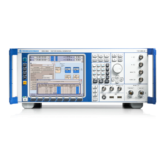
R&S SMU200A Contents "Putting into Operation" Contents - Chapter 1 "Putting into Operation" 1 Putting into Operation ..............1.1 Introduction - Putting into Operation..............Legend for Front Panel View................Legend for Rear Panel View................1.11 Putting into Operation..................1.15 Unpacking the Instrument ..............1.15 Setting up the Instrument or Installing it in a 19"... - Page 17 Front Panel View R&S SMU200A Figure 1-1 Front panel view 1007.9822.62 I-1.2...
-
Page 18: Putting Into Operation
R&S SMU200A Introduction - Putting into Operation 1 Putting into Operation Introduction - Putting into Operation Chapter 1, "Putting into Operation" explains the control elements and connectors of the Vector Signal Generator R&S SMU with the aid of the front and rear views and describes how to put the instrument into operation. - Page 19 Legend for Front Panel View R&S SMU200A Display The large display clearly shows all main settings See chapter 3, section and signal generator states. "Display" The display is divided into three sections: - Frequency and level display with info line - Block diagram - Winbar with labelled softkeys The frequency and level display section with...
- Page 20 R&S SMU200A Legend for Front Panel View Keypad for data entry Keypad for data entry See chapter 3, section "Setting Parameters" 0...9 Entry of numeric values Entry of decimal point +/– Entry of sign Entry of letters Entry of a space *...
- Page 21 Legend for Front Panel View R&S SMU200A Keys for data entry See chapter 3, section "Selecting a Unit - The unit keys can either select a unit and thus Setting Parameters" determine the absolute value, or change the unit, i.e. trigger a recalculation without changing the absolute value.
- Page 22 R&S SMU200A Legend for Front Panel View Keys for setting parameters See chapter 3, section "Setting Parameters", and chapter 4, section "RF Signal and Analog Mod - A Mod-RF A" FREQ Activates frequency entry. In the two-path mode, the frequency entry field that was active last is activated.
- Page 23 Legend for Front Panel View R&S SMU200A Keys for settings and navigation in the display and for setting parameters DIAGRAM Brings the block diagram to the See chapter 3, section "Setting Parameters" foreground. Active menus are minimized. Active menus are indicated by the buttons in the menu bar.
- Page 24 R&S SMU200A Legend for Front Panel View Keys for setting and navigation in the display and See chapter 3, section "Setting Parameters for setting parameters Arrow keys Vary the entry value or highlight a selected list item in the editing mode.
- Page 25 Legend for Front Panel View R&S SMU200A Trigger inputs and outputs TRIGGER 1 Input for triggering digital See data sheet and modulations and standards and ARB chapter 4, section (paths A and B). "Global Trigger/Clock/Input MARKER 1, 2 Outputs 1 and 2 for triggering and Settings –...
- Page 26 R&S SMU200A Legend for Front Panel View Keys for setting the display CLOSE Closes the active menu. See chapter 3, section If the entry mode is active, changes "Menu Operation" are cancelled. If settings in this menu require acknowledgement by means of an Accept button, a query is displayed asking whether the changes made should be cancelled.
- Page 27 Legend for Rear Panel View R&S SMU200A Fig. 1-2 Rear panel view 1007.9822.62 1.10...
-
Page 28: Legend For Rear Panel View
R&S SMU200A Legend for Rear Panel View Legend for Rear Panel View This section gives an overview of connectors on the rear panel of the R&S SMU. Each connector is briefly described and a reference is given to the chapters containing detailed information. For technical data of the connectors refer to the data sheet. - Page 29 Legend for Rear Panel View R&S SMU200A I/Q/DATA/CLOCK I/Q/DATA/CLOCK Provided for future upgrades Reference signal output REF OUT See data sheet and Output for external reference signal chapter 4, section "RF Reference Frequency - Reference Oscillator" Reference signal input REF IN See data sheet and Input for external reference signal chapter 4, section...
- Page 30 R&S SMU200A Legend for Rear Panel View Monitor Connector for external monitor See data sheet and chapter 1, section "Connecting an External Monitor" and chapter 8, section "Monitor Connector (MONITOR)" AUX I/O interface See chapter 4, section "Global Trigger/Clock/External Inputs - Setup"...
- Page 31 Legend for Rear Panel View R&S SMU200A RF A / RF B RF A / RF B Provided for future upgrades Clock signal output CLOCK OUT See data sheet and Output for internal (bit or symbol) chapter 4, section "Data clock signal (path A, the internal and Signal Sources in clock signal of path B can be output...
-
Page 32: Putting Into Operation
R&S SMU200A Putting into Operation Putting into Operation The following section describes the procedure for putting of the instrument into operation and the connection of peripherals such as printer and monitor. It contains general safety instructions for instrument operation. The installation of options and the firmware update are described in Chapter 4 of the Service Manual (supplied with the instrument on the CD-ROM). -
Page 33: Safety Instructions
Putting into Operation R&S SMU200A Safety Instructions General Precautions Caution! Prior to putting the instrument into operation, check the following: • The covers of the housing are in place and screwed on, • Vents are not obstructed. Make sure that the air can escape freely through the vents at the rear and at the sides. -
Page 34: Connecting The R&S Smu To The Ac Supply
R&S SMU200A Putting into Operation Connecting the R&S SMU to the AC Supply The R&S SMU is automatically matched to the applied AC voltage (see rear panel). There is no need to set the voltage manually or change fuses. The AC supply connector is at the rear of the unit (see below). -
Page 35: Start Display And Booting The R&S Smu
Putting into Operation R&S SMU200A Start Display and Booting the R&S SMU After instrument switch-on, the installed BIOS version and the processor characteristics are indicated for a few seconds in the start display. After this, the Windows XP Embedded operating system boots and then the instrument firmware. During booting of the instrument firmware, a selftest is performed. -
Page 36: Function Check
R&S SMU200A Function Check Function Check The signal generator automatically monitors the main functions when the instrument is switched on and continuously during operation. If a fault is detected, ERROR is displayed in the info line together with a brief error description. For in-depth identification of the error, press the key. -
Page 37: Windows Xp Embedded
WindowsXP Embedded R&S SMU200A WindowsXP Embedded Caution: Drivers and programs used in the instrument under WindowsXP have been adapted to the signal generator. To avoid impairment of instrument functions, only the settings described below are permissible. Existing software must only be modified with update software released by Rohde &... -
Page 38: Connecting An External Keyboard
R&S SMU200A Connecting an External Keyboard Connecting an External Keyboard A commercial, external keyboard with USB interface can be connected to the R&S SMU. A keyboard simplifies entry of list items, comments, file names, etc. and is a prerequisite for convinient operation of Windows XP. -
Page 39: Connecting An External Monitor
Connecting an External Monitor R&S SMU200A Connecting an External Monitor Caution: The monitor must be connected only when the instrument is switched off (STANDBY) to prevent damage to the monitor and the R&S SMU. Do not modify the screen driver (Display type) and the display configuration since this will impair instrument operation. -
Page 40: Connecting The R&S Smu To A Network (Lan)
R&S SMU200A Connecting the R&S SMU to a Network (LAN) Connecting the R&S SMU to a Network (LAN) The R&S SMU is equipped with a network interface and can be connected to an Ethernet LAN (local area network). Provided the appropriate rights have been assigned by the network administrator, files can be transmitted via the network, and network resources, e.g. - Page 41 Connecting the R&S SMU to a Network (LAN) R&S SMU200A Networks using fixed IP addresses In networks using fixed IP addresses, the addresses are mostly assigned by the network administrator. A fixed IP address must be entered in the Start - Control Panel menu of Windows XP (see "Entering the IP Address"...
- Page 42 R&S SMU200A Connecting the R&S SMU to a Network (LAN) 2. Click Control Panel and then Network and Internet Connections. 3. Click Network Connections at the bottom right of the Network and Internet Connections menu. 4. Click LAN Area Connection in the Network Connections menu (at the right) 1007.9822.62 1.25...
- Page 43 Connecting the R&S SMU to a Network (LAN) R&S SMU200A 5. On the General tab, select Internet Protocol (TCP/IP) in the field This connection uses the following items: and then click the Properties button. 6. In the Internet Protocol (TCP/IP) Properties menu, enter the IP address in the Use the following IP address: field (the complete data can be queried from the network administrator).
- Page 44 R&S SMU200A Connecting the R&S SMU to a Network (LAN) Query Computer Name 1. Open the start menu with the Windows key, select My Computer and open the context menu by pressing the right mouse key. 2. Click Properties and select the Computer Name tab in the menu. The computer name is displayed under Full Computer Name:.
- Page 45 Connecting the R&S SMU to a Network (LAN) R&S SMU200A However, the hard disk of a computer also connected to the network can be accessed from the R&S SMU relatively easily. The only precondition for this is that the desired directory the R&S SMU should access is enabled on the remote computer.
-
Page 46: Configuration For Manual Remote Control
R&S SMU200A Connecting the R&S SMU to a Network (LAN) Configuration for Manual Remote Control The R&S SMU can be manually controlled from an external PC via a network link. The instrument is operated with the aid of the Windows program Remote Desktop Connection which is provided by Microsoft in the download area of the Internet (http://www.microsoft.com). - Page 47 Connecting the R&S SMU to a Network (LAN) R&S SMU200A 3. Activate check box Allow users to connect remotely to this computer Enable Manual Remote Control on the PC The Remote Desktop Connection program of Microsoft is available on the Internet for the Windows 95...
- Page 48 R&S SMU200A Connecting the R&S SMU to a Network (LAN) 3. Enter the instrument and user ID of the R&S SMU in the General tab of the extended menu which is opened with the Options>> button. 4. Login data can be stored with the Save As button. If it is stored as a default.rdp file, the connection to the R&S SMU is offered as the default when the program is started.
- Page 49 Connecting the R&S SMU to a Network (LAN) R&S SMU200A 6. The connection is established when the Connect button is pressed. After link setup, the generator screen is displayed on the external PC. Operation is possible with the mouse and/or the keyboard. Front-panel keys without a corresponding key on the keyboard can be replaced by key combinations (see table in Chapter 3, section "Legend of Front-Panel Controls").
- Page 50 R&S SMU200A Contents - Getting Started Contents - Chapter 2 "Getting Started" 2 Getting Started ................2.1 Introduction - Getting Started ................Baseband Section of R&S SMU................RF Section of R&S SMU ..................Applications of the Two-Path R&S SMU ............. Two Baseband Generators, One RF Path ..........One Baseband Path and Two RF Paths ..........
- Page 51 Contents - Getting Started R&S SMU200A 1007.9822.62 I-2.2...
-
Page 52: Getting Started
R&S SMU200A Introduction - Getting Started 2 Getting Started Introduction - Getting Started The main field of application of the R&S SMU is the generation of digitally modulated signals. The R&S SMU uses I/Q (vector) modulation. Digital data streams are converted to an I/Q baseband signal. The baseband signal is then D/A-converted and modulated onto the desired RF carrier frequency with the aid of an I/Q modulator. - Page 53 Introduction - Getting Started R&S SMU200A In the R&S SMU, a digitally modulated signal can be generated in two ways: 1. The I/Q signal is generated internally in the R&S SMU. In this case the instrument must be equipped with at least one baseband generator (option R&S SMU-B10) and at least one baseband main module (option R&S SMU-B13).
- Page 54 R&S SMU200A Introduction - Getting Started 2. An external analog I/Q signal is directly applied to the I/Q modulator of the R&S SMU (Analog Wideband I/Q operation). In this mode, the entire bandwidth of the I/Q modulator can be utilized. The various capabilities of the baseband section (AWGN, addition of signals, etc) are disabled, however.
-
Page 55: Baseband Section Of R&S Smu
Baseband Section of R&S SMU R&S SMU200A Baseband Section of R&S SMU The baseband section of the R&S SMU is fully digital and contains the hardware for generating and processing I/Q signals. The baseband section may contain two paths. Baseband generator (option R&S SMU-B10): The generator produces baseband signals. It contains modules for real time signal generation and an arbitrary waveform generator (ARB). -
Page 56: Rf Section Of R&S Smu
R&S SMU200A RF Section of R&S SMU RF Section of R&S SMU The RF section of the R&S SMU may also contain two paths. An RF path is configured by installing a frequency option that comprises all required modules including synthesizer, output section with I/Q modulator and attenuator. -
Page 57: Applications Of The Two-Path R&S Smu
Applications of the Two-Path R&S SMU R&S SMU200A Applications of the Two-Path R&S SMU The modular design of the R&S SMU allows the instrument to be equipped with two paths. This allows a multitude of applications to be performed for which several signal generators were previously required. -
Page 58: One Baseband Path And Two Rf Paths
R&S SMU200A Applications of the Two-Path R&S SMU One Baseband Path and Two RF Paths Possible applications: • Generation of a modulated signal on path A and a CW interferer on path B Fig. 2-5 Operation of R&S SMU with one baseband generator and two RF paths 1007.9822.62... -
Page 59: Fully Equipped Two-Path Instrument
Applications of the Two-Path R&S SMU R&S SMU200A Fully Equipped Two-Path Instrument Possible applications: • Generation of a wanted signal and an interfering signal for receiver tests • Generation of multicarrier signals with extremely wide bandwidth (>80 MHz) Fig. 2-6 Fully equipped two-path instrument 1007.9822.62... -
Page 60: Description Of Individual Diagram Blocks
R&S SMU200A Description of Individual Diagram Blocks Description of Individual Diagram Blocks Available Blocks Block Function of block Status display in the block Effect of TOGGLE ON/OFF key Baseband source is configured Selected modulation Switches the selected modulation Baseband A or B and activated (digital standard, digital modulation or ARB) on or off. - Page 61 Description of Individual Diagram Blocks R&S SMU200A Baseband B block Configures the second baseband source (if installed). The block is displayed only if the instrument contains two baseband generators (option R&S SMU-B10). Depending on the installed software option, various digital standards, user-configured digital real time modulation or the built-in waveform generator (ARB) can be selected.
-
Page 62: Blocks Of The Rf Section
R&S SMU200A Description of Individual Diagram Blocks Blocks of the RF Section I/Q Mod A block The (first) I/Q modulator is configured in this block. Also the Analog Wideband I/Q mode can be selected here, which allows external I/Q signals to be directly applied to the I/Q modulator, i.e. - Page 63 Description of Individual Diagram Blocks R&S SMU200A RF/A Mod A In this block, the RF parameters and the analog modulation modes of path A are set. The active analog modulation modes are displayed in the block. The key switches the RF signal of the path on and off. When TOGGLE ON/OFF the signal is switched off, the switch before the RF output symbol is open.
-
Page 64: Example Of Setup
R&S SMU200A Example of Setup Example of Setup A central element of the R&S SMU display is the block diagram that illustrates the signal flow. Each block represents an important section of signal generation. Thus the user always knows the position at which a parameter has an effect in the signal flow. - Page 65 Example of Setup R&S SMU200A Step 2: Select and activate digital modulation Select the Baseband A block by turning the rotary knob. Press the rotary knob to open the menu where the digital modulation can be selected (different modulation modes are available depending on the options installed).
- Page 66 R&S SMU200A Example of Setup Press the rotary knob to open the Custom Dig. Mod. menu. Select the Symbol Rate parameter by turning the rotary knob, and then enter the desired symbol rate with the aid of the numeric keypad and the unit keys.
- Page 67 Example of Setup R&S SMU200A Select the Coding parameter by turning the rotary knob. Press the button to open the selection list. Select Off by turning the rotary knob and press it to activate the selected item. Set Modulation Type QPSK and Filter Root Cosine with Roll Off Factor 0.3 in the same...
- Page 68 R&S SMU200A Example of Setup Finally, switch on digital modulation by selecting State On. Press the DIAGRAM key to display the complete block diagram. To indicate the active state, the Baseband block is displayed in blue. The I/Q Mod block is automatically activated.
- Page 69 Example of Setup R&S SMU200A The menu can be displayed in the foreground by clicking the softkey below the button in the Windows list. Press the key to HIDE minimize the menu again. Step 3: Set frequency and level and activate RF signal Press the key to FREQ...
- Page 70 R&S SMU200A Example of Setup Enter the level in the same way after pressing key. LEVEL Press the DIAGRAM to display the complete block diagram. Select the RF/A Mod block by turning the rotary knob and activate it by pressing the key.
- Page 71 Example of Setup R&S SMU200A Step 4: Select graphics display of I/Q signal Select the Graphics block and open the respective menu by turning the rotary knob. Activate display of the I/Q diagram by selecting State On with the rotary knob.
- Page 72 Contents - Manual Operation R&S SMU200A Contents - Chapter 3 "Manual Operation" Manual Operation ................3.1 Introduction - Manual Operation................Operating Concept ....................Display......................... Frequency and Level Setting - Display........... Status Information and Messages - Display........... Info Window - Display................Block Diagram - Display ............... 3.11 Winbar and Softkeys - Display .............
- Page 73 R&S SMU200A Contents - Manual Operation 1007.9822.62 I-3.2...
-
Page 74: Manual Operation
R&S SMU200A Introduction - Manual Operation 3 Manual Operation Introduction - Manual Operation The Vector Signal Generator R&S SMU can be operated intuitively either via the interactive block diagram or via a menu tree. All menus are in the form of windows that can be operated in the same way. - Page 75 Operating Concept R&S SMU200A Operation via the graphics interface Menus are assigned to the specific function blocks in the block diagram. The function blocks represent elements of signal generation, e.g. the baseband block which contains all menus required for baseband signal configuration.
- Page 76 R&S SMU200A Operating Concept Operation corresponds to the Windows concept To offer the user a familiar environment, operation is very similar to operation of Windows user interfaces. All menus and tables are made up of known elements, e.g. selection lists, check boxes, or entry fields.
- Page 77 Operating Concept R&S SMU200A The Winbar gives an overview of menus and simplifies their access. The menus are displayed on top of the block diagram but they can be "hidden", i.e. displayed in the form of a button in the Winbar at the lower end of the screen ( key).
- Page 78 R&S SMU200A Operating Concept Each help page is part of a comprehensive online help function which can be called by means of an index, a content tree or the buttons. Previous Next Messages indicate the current instrument state A great variety of different messages such as status messages, error messages, warnings or information are displayed in the header field of the screen.
- Page 79 Operating Concept R&S SMU200A Graphical display of output signal in a diagram The output signal can be graphically displayed in a number of diagrams. This allows a fast check of signal characteristics. Zoom functions and the insertion of a reference trace permit in-depth evaluation without an external analyzer being required.
-
Page 80: Display
R&S SMU200A Display Display The display shows the current signal generator state and offers graphical elements for direct operation. It is divided into three sections: • The frequency and level display with info line indicates the main output signal parameters and reports the current state with status, error and warning messages. -
Page 81: Frequency And Level Setting - Display
Display R&S SMU200A Frequency and Level Setting - Display Frequency/level settings and a few status messages (see below) are displayed in the header field of the screen. The display may vary depending on the instrument's operating mode: In the case of two-path instruments, the RF information for the two paths is displayed in two lines. In the sweep mode, the current frequency or level of the output signal is displayed. -
Page 82: Info Window - Display
R&S SMU200A Display Brief messages Brief messages report automatic settings in the instrument (e.g. switching off of incompatible types of modulation) or on illegal entries that are not accepted by the instrument (e.g. range violations). They are displayed in the info line on a yellow background. They are displayed on top of status information or permanent messages. - Page 83 Display R&S SMU200A Delete All Clears all messages. This button is available only if the history of the messages is displayed. Remote-control command: SYST:ERR:ALL Delete Vol. Clears all brief messages. This button is available only if the history of the messages is displayed.
-
Page 84: Block Diagram - Display
R&S SMU200A Display Block Diagram - Display The block diagram shows provided options, signal configuration and the currently selected signal flow of the generator with inputs and outputs used. Signal generation can be completely operated from the block diagram. The highlighted function block can be directly switched on and off with the TOGGLE key. - Page 85 Display R&S SMU200A Clicking the rotary knob (front panel) or the config... button (mouse) opens the associated setting menu. In all function blocks where the signal flow can be influenced, the top menu level for setting signal routing parameters is offered. The input/output symbols in the block diagram show the currently used inputs and outputs of the signal generator.
-
Page 86: Winbar And Softkeys - Display
R&S SMU200A Display Symbols and lines are displayed in different colours depending on their function. • The baseband signal is indicated by a three line arrow, the I- and Q- components of the signal by a single-line arrow. • Addition of signals is indicated by the summation sign. -
Page 87: Menu Structure - Display
Display R&S SMU200A Menu Structure - Display The parameters are set in the menus. Menus are called either via the function blocks in the diagram or by means of the key. The menus are displayed on top of the block diagram. If the menu buttons MENU assign menu-specific functions to the softkeys, the Winbar is hidden. - Page 88 R&S SMU200A Display Selection field button indicates that a selection can be made from a list. The fold-down selection list is displayed below the selection field. Depending on the number of entries, the full list or only part of it is shown.
- Page 89 Display R&S SMU200A Tables Tables are made up of a header, which normally contains the column labels, and lines containing the text. Graphical display Graphical displays show signal characteristics and in some of them the element to be set can be selected.
-
Page 90: Graphical Display Of Output Signal Characteristics
R&S SMU200A Display Graphical Display of Output Signal Characteristics The graphical display of the output signal enables the user to rapidly check signal characteristics without connecting an analyzer. Zoom functions and the display of a reference trace allow in-depth evaluation. The diagram is displayed on top of the block diagram. It can be minimized and called in the same way as a menu. -
Page 91: Setting Parameters
Setting Parameters R&S SMU200A Setting Parameters The R&S SMU offers several and sometimes alternative possibilities for setting parameters. Operation is possible from the front panel, with the aid of a mouse and/or from a PC keyboard. Operation of the R&S SMU with the aid of these control media is shown in the tables below. Frequency and level are directly set in the header area of the display using the keys. - Page 92 R&S SMU200A Setting Parameters Menu area: The cursor is set to another menu area. Menu: The menu is closed and the cursor changes to the next higher control level. Frequency/level field: The cursor is set on the previously active menu or, if no menu was active, on the first function block in the diagram.
-
Page 93: Selecting A Control Element - Setting Parameters
Setting Parameters R&S SMU200A Selecting a Control Element - Setting Parameters Control elements are always selected in the same way no matter whether a function block in the diagram, a menu in the menu tree, a parameter in the menu or an entry in a list or table is concerned. •... -
Page 94: Selecting And Exiting A Menu Area - Setting Parameters
R&S SMU200A Setting Parameters Selecting and Exiting a Menu Area - Setting Parameters Some menus are organized in areas. The cursor can be moved either only within an area or between the higher-level menu areas. This applies to the File Select menus when files are saved or loaded. When the menu is called, one of the menu areas is highlighted by a blue frame. - Page 95 Setting Parameters R&S SMU200A • Clicking the rotary knob (= Enter) terminates the setting, i.e. selection of a file. The cursor is either set on the next higher menu level or the menu is closed as in our example. • The left/right cursor keys first shift the entry focus within the menu range form left to right (or vice versa);...
-
Page 96: Entering A Value - Setting Parameters
R&S SMU200A Setting Parameters Entering a Value - Setting Parameters Numeric and alphanumeric values can be edited in the entry fields. In the editing mode, cursors of different colour are used. A blue cursor indicates the overwrite mode, a green cursor the insert mode. key toggles between the two modes. -
Page 97: Selecting A Unit - Setting Parameters
Setting Parameters R&S SMU200A • New entry: The entry is started by clicking an alphanumeric key. • Editing: An existing value, e.g. a file name, can be changed in the insert mode (see example) or in the overwrite mode. Function Front panel PC keyboard Mouse... - Page 98 R&S SMU200A Setting Parameters yields Terminating the value entry with Enter If an entry is terminated by clicking the rotary knob (= Enter) or with the key, the unit displayed ENTER in the entry field next to the value is assigned (in the example ksym/s). yields If a unit is subsequently changed, i.e.
-
Page 99: Selecting A Value From A List - Setting Parameters
Setting Parameters R&S SMU200A Selecting a Value from a List - Setting Parameters button next to the value field indicates that a selection list is available. • Clicking the rotary knob (= Enter) opens the list. Selection is made by choosing an entry (item is highlighted) and confirmation with ENTER. -
Page 100: Terminating Entries - Setting Parameters
R&S SMU200A Setting Parameters Terminating Entries - Setting Parameters Variations by means of the rotary knob are immediately set, e.g. RF frequency variation. All other parameter settings have to be confirmed by a pressing the rotary knob or one of the unit keys (see also section "Selecting a Unit", page 3.24). -
Page 101: Restoring The Previous Value - Setting Parameters
Setting Parameters R&S SMU200A Restoring the Previous Value - Setting Parameters Parameter variations with the rotary knob are immediately set and therefore not reversible. Normally, values cannot be restored also in the case of mouse control because no explicit confirmation is required in this case and entries are automatically confirmed when the entry or selection field is exited. -
Page 102: Menu Operation
R&S SMU200A Menu Operation Menu Operation Menus are operated with the aid of the Winbar buttons or front-panel softkeys and with the HIDE keys on the front panel. CLOSE DIAGRAM REARR If the Winbar is covered by a menu, it can be called to the front with the key. - Page 103 Editors R&S SMU200A List Editor The User Correction and List Mode menus provide the list editor for defining the frequency/level value pairs. The associated buttons call up the list editor. • The selected list is displayed. If no list has been selected, a blank list of only one row is displayed. •...
- Page 104 R&S SMU200A Editors Function Front panel PC keyboard Mouse Enter value. Use the numeric keys to Use the numeric keys to enter the value and terminate enter the value and terminate the entry by pressing the unit the entry by pressing the key.
- Page 105 Editors R&S SMU200A Data Editor The Data Editor can be used to internally generate binary data lists for digital modulation and digital standards. A list of binary values with a maximum length of 2^31 bits can be entered in the Data Editor. This value corresponds to a file size of approx.
- Page 106 R&S SMU200A Editors Function Front panel PC keyboard Mouse Enter value. Use the numeric keys to Use the numeric keys to enter the values 0 or 1. enter the values 0 or 1. Depending on selected mode, either insertion or overwrite, the value is either inserted or it replaces an existing value.
- Page 107 Editors R&S SMU200A Function Front panel PC keyboard Mouse Display and edit the values Use the rotary knob or the Mark the Hex button and Click the Hex button. in hexadecimal form. cursor keys to mark the Hex press the Enter key. button, click the rotary knob or press the ENTER key.
- Page 108 R&S SMU200A Editors Control and Marker List Editor The control and marker signals for digital modulation and digital standards can be very conveniently graphically defined in a Control and Marker List Editor. The four available marker signals – and, with custom digigital modulation, the CW, Hop, Burst Gate and Lev Att control signals –...
- Page 109 Editors R&S SMU200A When ramps are set between existing ramps, the transition of the new ramp is also defined by the status of the signal before the new ramp. For this reason, a ramp that has already been set can be assigned low/low or high/high transition (as in the example), i.e.
- Page 110 R&S SMU200A Editors Function Front panel PC keyboard Mouse Set ramp. Use the rotary knob or the Use the cursor keys to move Double click cursor; the cursor keys to move the the cursor to the position cursor changes colour and cursor to the position where where the ramp is to be the ramp is inserted.
-
Page 111: Help System
Help system R&S SMU200A Function Front panel PC keyboard Mouse Create new list Mark the Control List... Mark the Control List... Double-click the Control (Custom Dig Mod only). button in the list management button in the list management List... button in the list submenu of the individual submenu of the individual management submenu of the... - Page 112 R&S SMU200A Help system Operation of context-sensitive help Function Front panel PC keyboard Mouse Opens the help system Press F1 key. Press HELP key. The help page for the respective parameter is displayed. Closes the help system Press F1 key again. Press HELP key again.
-
Page 113: File Management
File Management R&S SMU200A File Management The R&S SMU uses files to save all instrument data, i.e. system and user data. The user data includes saved instrument settings, data for the different digital standards, lists for the List mode and the user correction as well as the waveforms for the arbitrary waveform generator. -
Page 114: File Select Menu
R&S SMU200A File Management The files are differentiated according to their extensions; each type of file is assigned a specific file content. The extension is usually of no consequence to the user since access to the files occurs in the individual menus where only the relevant type of file is available. - Page 115 File Management R&S SMU200A When a file is saved or created, its name is user-selectable; the extension is assigned automatically and cannot be entered. The file is saved to the selected path. Operation is similar to the operation of menus with several areas (see section "Selecting and Exiting a Menu Area - Setting Parameters", page 3.21): By using the rotary knob or cursor keys, the area is...
- Page 116 R&S SMU200A File Management File Manager The File Manager allows general file management such as copying, shifting, renaming and deleting files as well as generating new directories. Thus, also externally created files, for example waveforms created by using the R&S WinIQSIM program, can be saved to the R&S SMU by copying them from a memory stick or a network to the internal hard disk.
- Page 117 File Management R&S SMU200A • Create new directory: Mark drive or directory level where the new directory is to be created and then press the Create New button/softkey. An entry window for entering the directory name opens. Enter the name and Directory press the Enter key.
-
Page 118: Manual Remote Control
R&S SMU200A Manual Remote Control Manual Remote Control The R&S SMU can be remote-controlled from an external PC. This allows convenient operation of the vector signal generator from the desktop although the instrument is integrated in a rack in the next room. - Page 119 Manual Remote Control R&S SMU200A For return to direct operation on the R&S SMU, the external user must be logged off and the local user logged on. The external user can log off in the Start menu on the external controller by clicking Disconnect in the lower right-hand corner of menu.
-
Page 120: Legend Of Front-Panel Controls
R&S SMU200A Legend of Front-Panel Controls Legend of Front-Panel Controls The table lists all key functions available on the front panel. Key combinations used on the PC keyboard to trigger key functions on the instrument front panel are also described. Keyboard labels are described in alphabetical order. - Page 121 Legend of Front-Panel Controls R&S SMU200A Front-panel key Key of PC keyboard Function HIDE CTRL+ H Minimizes the active menu. Pressing the respective button in the Winbar opens the menu again. INFO CTRL + I Opens/closes the info window INSERT Einfg Activates the insert mode.
-
Page 122: Menus
R&S SMU200A Menus Menus Menus can be opened using the key. All menus involved in signal generation can also be opened Menu from the function blocks. The System and Environment menus, where general instrument settings are made, can also be accessed using the key. - Page 123 Menus R&S SMU200A RF/A Mod A/B menus Graphics menus BERT menus Setup menus Help menus 1007.9822.62 3.50...
- Page 124 R&S SMU200A Contents "Instrument Functions" Contents - Chapter 4 "Instrument Functions" Instrument Functions .................4.1 Overview of Instrument Functions..............General Instrument Settings ..............4.3 Overview of General Instrument Settings............Default Instrument Settings - Preset Key ............General Configuration of Instrument - Setup Key ..........Internal Adjustments - Setup-System..........
- Page 125 Contents "Instrument Functions" R&S SMU200A RF Level - Level - EMF................... 4.46 Level - EMV Menu ................4.47 Automatic Level Control - ALC ............... 4.50 Automatic Level Control Menu ............4.51 User Correction ....................4.52 User Correction Menu ............... 4.52 Overvoltage Protection ...................
- Page 126 R&S SMU200A Contents "Instrument Functions" Internal Clock and Internal Data ..........4.135 Internal Clock and External Synchronous Data ..... 4.136 External Clock and External Synchronous Data....4.137 External Clock and Internal or External Asynchronous Data. 4.137 Control Signals ................4.138 Power Ramping and Level Attenuation ......
- Page 127 Contents "Instrument Functions" R&S SMU200A Timing Offset ................... 4.253 Demultiplexer - 3GPP FDD ............. 4.253 Power Control - 3GPP FDD ............4.253 Summation and Filtering - 3GPP FDD ..........4.254 Multicode - 3GPP FDD..............4.254 3GPP FDD Menu..................4.255 Filtering, Clipping, ARB Settings - 3GPP FDD........ 4.268 Trigger/Marker/Clock - 3GPP FDD..........
- Page 128 R&S SMU200A Contents "Instrument Functions" Figures Fig. 4-1 Definition of IQ modulator in IS2000 and R&S SMU ............4.89 Fig. 4-2 Test setup for bit or block error rate measurement............4.105 Fig. 4-3 PRBS generation is restarted by the Restart signal when the signal begins anew..4.106 Fig.
- Page 129 Contents "Instrument Functions" R&S SMU200A Tables Table 4-1 Preset state - important generator settings..............Table 4-2 Combinations of signal routings for two-path instruments..........4.128 Table 4-3 PRBS generators ...................... 4.131 Table 4-4 Modulation type and associated mapping ..............4.142 Table 4-5 Permissible coding combinations for modulation symbols and modulation type..
-
Page 130: Instrument Functions
R&S SMU200A Overview of Instrument Functions Instrument Functions Overview of Instrument Functions This chapter explains the functions of the vector signal generator and the options available in the setting menus. The associated IEC/IEEE-bus command is specified for each parameter (where applicable). The description begins with the general instrument settings which do not directly affect signal generation. - Page 131 Overview of Instrument Functions R&S SMU200A The RF signal is configured and the analog modulations activated in the RF/A Mod function block: • CW mode (section "Overview of RF Signal and Analog Modulation", page 4.40) • List mode (section "List Mode - List", page 4.56) •...
-
Page 132: General Instrument Settings
R&S SMU200A Overview of General Instrument Settings General Instrument Settings Overview of General Instrument Settings The section "General Instrument Settings" describes the settings which do not directly affect signal generation. Most of these settings can only be accessed by means of menus which are opened using keys. This does not apply to the graphical representation of output signals which is activated in the Graphics function block, or settings which can additionally be called up in the menus of the function blocks, e.g. -
Page 133: General Configuration Of Instrument - Setup Key
General Configuration of Instrument - Setup Key R&S SMU200A General Configuration of Instrument - Setup Key key opens the System menu used to set general instrument parameters and the SETUP Environment menu used to configure the instrument interfaces. Most submenus of this key can be accessed only via the key or the menu tree ( key), with SETUP... - Page 134 R&S SMU200A General Configuration of Instrument - Setup Key The Internal Adjustments menu is opened up using the key under System. SETUP MENU Starts all internal adjustments for which no external measuring Adjust All equipment is needed. The adjustments with external measuring equipment are described in the Service Manual (supplied).
-
Page 135: Hardware Config
General Configuration of Instrument - Setup Key R&S SMU200A Starts the adjustment for the I/Q modulator for the currently set ...Current Frequency frequency, I/Q swap, and baseband gain. The I/Q modulator is adjusted with respect to carrier leakage, IQ imbalance and quadrature. Adjustment for only the set frequency is considerably faster than adjustment across the entire frequency range. -
Page 136: Gui Update
R&S SMU200A General Configuration of Instrument - Setup Key Remote-control command: :DIAG:BGIN? "MBRD" Response: "MBRD 1141.3501.02 1.5.3 100023" Gui Update... - Setup/System The Start/Stop Gui Update menu... provides the possibility to switch off update of the displayed parameters in order to increase speed for certain settings. The indicated values are not updated and may therefore differ from the intern, used values. -
Page 137: Software / Options
General Configuration of Instrument - Setup Key R&S SMU200A Software / Options... - Setup/System The Software / Options... shows the firmware version of the instrument software as well as all installed hardware and software options. Note: Software options purchased at a later stage can be activated with a keycode. The activation code is supplied with the software option. - Page 138 R&S SMU200A General Configuration of Instrument - Setup Key Section Loaded Modules is provided for service purposes. It lists all loaded software modules with their versions and offers a short description of each module. 1007.9845.32...
-
Page 139: Install Sw-Option
General Configuration of Instrument - Setup Key R&S SMU200A Install SW-Option... - Setup/System Newly purchased software options are enabled in the Install SW-Options menu..They are ready to operate after they are enabled by means of a key code supplied with the option. Only if the R&S SMU is equipped with an older firmware version, a firmware update prior to enabling the software option may be required. -
Page 140: Check Front Panel - Setup-Test
R&S SMU200A General Configuration of Instrument - Setup Key Remote-control commands: :DIAG1:POIN:CAT? (Command lists all test points) :DIAG1:POIN? 'DIAG_IQOP3_LCM_CAL_I' (With remote control, voltage measurement starts as soon as the test point is selected) Displays the measured voltage measurement at the selected test Voltage point. -
Page 141: Global Trigger/Clock/External Input Settings - Setup-Environment
General Configuration of Instrument - Setup Key R&S SMU200A Global Trigger/Clock/External Input Settings - Setup-Environment The Global Trigger/Clock/External Inputs menu can be opened using the key under SETUP MENU the Environment menu as well as in all clock and trigger menus of the Baseband function block. This menu is used to determine the physical characteristics of the input connectors for trigger, clock and control signals of the baseband and RF section. - Page 142 R&S SMU200A General Configuration of Instrument - Setup Key Sets the high/low threshold in volts for the trigger and control signal Threshold Trigger/Control inputs of the baseband section. Input The setting affects the TRIGGER 1 and 2 inputs (BNC connectors at the front and rear of the instrument) and the CW, BURST and LEV_ATT inputs (AUX I/O interface at the rear of the instrument).
-
Page 143: User Marker - Aux Io - Setup-Environment-Global
General Configuration of Instrument - Setup Key R&S SMU200A The polarity of the clock output at the rear panel is set in the Clock Output (BNC Rear Panel) section. Indicates the path for which the clock signal at the CLOCK OUT Clock Source connector is to be output (always path A). - Page 144 R&S SMU200A General Configuration of Instrument - Setup Key BURST (input/output Path B). This signal corresponds to the control signal for envelope curve control. With external envelope curve control, the interface is input, otherwise output. The external envelope curve control is activated in the Power Ramp Control submenu in the Custom Digital Modulation menu of the Baseband function block.
- Page 145 General Configuration of Instrument - Setup Key R&S SMU200A Connection Description 1... 25 - ⊥ Ground 26 - LEV ATT Signal input/output for controlling the level attenuation (Path A only). With external envelope curve control (Custom Digital Modulation only), the pin is the input for the control signal LEV_ATT.
-
Page 146: Remote Gpib - Setup-Remote
R&S SMU200A General Configuration of Instrument - Setup Key The polarity of the No Signal (Blank) Marker is set in the No Signal (Blank) Marker section. Polarity Selects the polarity of the No Signal Marker. If Positive is selected, the signal is high (2.5 V) when the marker is active; if Negative is selected, the signal is low (0 V). -
Page 147: Help - Setup-Help
Switching to Manual Control - Local Key R&S SMU200A Help - Setup-Help The Help submenu offers comprehensive online help for the R&S SMU. A desired topic can be selected via the table of contents (select Manual) or the index (select Index). For context-sensitive information about a marked parameter, press the key. -
Page 148: Messages - Info Key
R&S SMU200A Messages - Info Key Messages - Info Key key opens a window containing a detailed description of every message displayed in the info INFO bar, see chapter 3, section Bar" and chapter 9, section "Error "Info and Status Messages". - Page 149 Help System - Help Key R&S SMU200A Contents in the navigation panel The contents list is used to open the individual help pages. It has a hierarchical structure. The highlighted line indicates where the currently displayed page is within the contents list. Index in the navigation panel The index is used to call up all pages which contain the selected entry.
-
Page 150: Storing And Loading Instrument Data - File Key
R&S SMU200A Storing and Loading Instrument Data - File Key Storing and Loading Instrument Data - File Key The R&S SMU allows complete instrument settings to be stored in files on the hard disk. Defined and complex instrument settings can then be reproduced at any time by loading this data. If required, these settings can be loaded to various signal generators. -
Page 151: File Menu
Storing and Loading Instrument Data - File Key R&S SMU200A File Menu The settings available in the File menu depend on the operation selected under Select Operation. Selects the file function. Select Operation Calls the menu for storing the current instrument Save... - Page 152 R&S SMU200A Storing and Loading Instrument Data - File Key File List Displays the files which are in the selected directory. If a file is highlighted, it is overwritten when the file is stored. Remote-control command: :MMEM:CAT? File Name Enter the file name of the file without file extension. This file is then created.
-
Page 153: Loading Instrument Settings - File
Storing and Loading Instrument Data - File Key R&S SMU200A Loading Instrument Settings - File If Recall is selected under Select Operation, the File menu provides options for loading complete instrument settings. Here it is possible to select whether the current or stored RF frequency and RF level settings are to be used. - Page 154 R&S SMU200A Storing and Loading Instrument Data - File Key Exclude Level The current level is retained when a stored instrument setting is loaded. Remote-control command: :SOUR1:POW:RCL EXCL Recall Load the selected configuration.: If an instrument setting in which a sweep was activated is stored, the sweep is started when the recall command is called.
-
Page 155: File Management - File
Storing and Loading Instrument Data - File Key R&S SMU200A File Management - File The File Management menu provides all the functions required for file management. Directories can be created, and files copied, deleted and moved between the directories on the drives (hard disk, memory stick and network drives). - Page 156 R&S SMU200A Storing and Loading Instrument Data - File Key Paste Pastes the file that has been copied or cut before. Remote-control command: - Rename Renames the selected file or directory. The new name can be entered in the New Filename window. Remote-control command: MMEM:MOVE "test02.dm_iqd","set2.dm_iqd"...
-
Page 157: Graphical Display - Graphics
Graphical Display of Signal Characteristics R&S SMU200A Graphical Display - Graphics Graphical Display of Signal Characteristics The R&S SMU can be used to graphically display the generated baseband signal. A selection of different signal displays assists the user in assessing and checking the increasingly complex modulation signals. -
Page 158: Graphics Settings Menu
R&S SMU200A Graphics Settings Menu Graphics Settings Menu The Graphics Settings menu for selecting the graphical display of the output signal is opened either in the Graphics function block or in the menu with the same name which is opened using the key. - Page 159 Graphics Settings Menu R&S SMU200A Trigger Source Defines the trigger for the starting time of the graphic recording. Remote-control command: - Software Recording of signals is started automatically in specified intervals. This asynchronous method is appropriate when a representative display of the complete signal is desired, as recording starts in a random time reference to the signal.
-
Page 160: Softkey Bar Of Graphics Window
R&S SMU200A Softkey Bar of Graphics Window Softkey Bar of Graphics Window At the bottom of each graphics window there are buttons for freezing and zooming the display and for defining and activating a reference curve. Freezes the current display. Clicking the button again reactivates the normal, permanently updated display. - Page 161 Softkey Bar of Graphics Window R&S SMU200A Clicking the button again hides the reference curves. The reference curves must be defined beforehand using the Copy to Ref button. Remote-control command: - Copy to ref Defines the current curve as the reference curve. A window opens in which the curve can be given a comment and a color.
- Page 162 R&S SMU200A Softkey Bar of Graphics Window Display area The comments entered for the defined reference curve are shown in the display area next the assigned color. A maximum of five colors (and reference curves) are available. If no reference curve is assigned to a particular color, the comment <empty>...
-
Page 163: Signal Displays - Graphics
Signal Displays - Graphics R&S SMU200A Signal Displays - Graphics All signal displays which are used for analyzing a baseband signal can be selected. A number of signal displays are only available if the corresponding signal is generated, e.g. Code Domain only available for (W)CDMA signals. -
Page 164: Vector Diagram - Graphics
R&S SMU200A Signal Displays - Graphics Vector Diagram - Graphics The Q component is displayed over the I component in the vector diagram. Each point is determined by a vector. The amplitudes of the signal components scaled to the peak envelope power (PEP) are plotted on the X and Y axis (minimum scaled amplitude = -1;... -
Page 165: Constellation Diagram - Graphics
Signal Displays - Graphics R&S SMU200A Constellation Diagram - Graphics In the constellation diagram, the Q component is also displayed over the I component. However, only the values at the constellation points (signal value at the ideal scanning instant of the symbol) are displayed, i.e. -
Page 166: Eye Diagram - Graphics
R&S SMU200A Signal Displays - Graphics Eye Diagram - Graphics The eye diagram displays synchronized and superimposed sections of either the inphase or quadrature components of the signal. The display width (eye length) is set at 2 symbols; several hundred curve segments are superimposed. The time (in the range -/+ 1 symbol) is plotted on the X axis, and the amplitude scaled to the peak envelope power (PEP) is plotted on the Y axis (minimum scaled amplitude = -1;... -
Page 167: Ccdf Display - Graphics
Signal Displays - Graphics R&S SMU200A CCDF Display - Graphics The Complementary Cumulative Distribution Function shows the probability with which the output signal will exceed the average power. The level over the average power is plotted from 0 to 20 dB on the X axis; the average power (RMS) corresponds to the origin. -
Page 168: Power Spectrum - Graphics
R&S SMU200A Signal Displays - Graphics Power Spectrum - Graphics With the spectrum display, the signal spectrum is calculated from the I/Q signal by means of Fast Fourier Transform (FFT). The power density over frequency is displayed. The power density is plotted on the Y axis, and the frequency is plotted symmetrically on the X axis (-sampling rate/2 to +sampling rate/2). -
Page 169: Rf Signal And Analog Mod - A Mod-Rf
Overview of RF Signal and Analog Modulations R&S SMU200A RF Signal and Analog Mod - A Mod-RF A Overview of RF Signal and Analog Modulations Settings for the RF output signal and analog modulation are made under "RF Signal and Analog Modulations". -
Page 170: Rf Frequency And Phase - Frequency - Phase
R&S SMU200A RF Frequency and Phase - Frequency - Phase Instruments connected downstream can be taken into consideration when setting the frequency and level by entering a frequency and/or level offset. Automatic level control ensures maximum level accuracy, even with I/Q modulation. User-specific lists which contain level correction values for any frequency range (User Correction) can be created to, for example, compensate the cable attenuation in a test assembly setup. -
Page 171: Frequency - Phase Menu
RF Frequency and Phase - Frequency - Phase R&S SMU200A The correlation is as follows: Freq in header = RF output frequency (= Freq in menu) + Freq offset (= Offset in menu) Frequency offset by the instrument (Offset in the Frequency menu) Frequency at the output Mixer of the instrument... - Page 172 R&S SMU200A RF Frequency and Phase - Frequency - Phase The frequency and offset are set in the top section of the menu. Sets the RF frequency of the RF output connector. The frequency Frequency entered and displayed here corresponds to the frequency at the RF output, i.e.
-
Page 173: Rf Reference Frequency - Reference Oscillator
RF Reference Frequency - Reference Oscillator R&S SMU200A RF Reference Frequency - Reference Oscillator In the internal reference mode the internal reference signal is available at the REF OUT connector (rear of instrument). The frequency of the internal reference signal is permanently set to 10 MHz. The frequency of the internal reference oscillator can be impaired by means of the EXT TUNE input (AUX I/Q connector at rear of instrument) (Frequency Adjustment;... - Page 174 R&S SMU200A RF Reference Frequency - Reference Oscillator Selects the source of the reference frequency. Source The internal reference signal of 10 MHz is used. Internal Remote-control command: :SOUR:ROSC:SOUR INT An external reference signal is used. The frequency External of the external reference signal must be selected under External Frequency.
-
Page 175: Rf Level - Level - Emf
RF Level - Level - EMF R&S SMU200A RF Level - Level - EMF Note: The message Level overrange/underrange appears in the status line if the set level (Level) or the displayed peak envelope power (PEP) (Digital Modulation or Digital Standard) is in the overrange (see data sheet). -
Page 176: Level - Emv Menu
R&S SMU200A RF Level - Level - EMF The level offset is entered in the Level menu. Here it is also possible to set the level without taking the offset into consideration, and to make other settings, such as level offset, attenuator mode, power-on state. - Page 177 RF Level - Level - EMF R&S SMU200A The offset-free level, attenuation mode, level offset and level limit are set in the top section of the menu. Sets the RF level of the RF output connector. Level The level entered and displayed here corresponds to the level at the RF output, i.e.
- Page 178 R&S SMU200A RF Level - Level - EMF The level settings are made only in the area of the High Power option. Only the high level range is available. The (Option High relays are not switched. Power only) Remote-control command: :OUTP:AMOD HPOW The level settings are made without switching the Fixed...
-
Page 179: Automatic Level Control - Alc
Automatic Level Control - ALC R&S SMU200A The power-on behavior of the R&S SMU and the level display in the display header are set in the Power-On /EMF Settings section. Selects the state which the RF output is to assume after the Power-On State instrument is switched on. -
Page 180: Automatic Level Control Menu
R&S SMU200A Automatic Level Control - ALC Automatic Level Control Menu The Automatic Level Control menu is opened either in the RF/A Mod function block or using the key under RF/A Mod. MENU The combined menu Level / EMF / ALC /UCOR provides access to the automatic level control settings in the lower section. -
Page 181: User Correction
User Correction R&S SMU200A User Correction The "User Correction" function is used to create and activate lists in which level correction values predefined by the user are freely assigned to RF frequencies. Correction is performed by the user- defined table values being added to the output level for the respective RF frequency. With frequencies which are not contained in the list, the level correction is determined by interpolation of the closest correction values. - Page 182 R&S SMU200A User Correction Activates/deactivates user correction. State The UCOR status message appears in the frequency and level display. Remote-control command: :SOUR:CORR:STAT ON Calls the File Select menu for selecting and creating a list or the File User Correction Data... Manager Remote-control command: :SOUR:CORR:CSET:CAT?
- Page 183 User Correction R&S SMU200A If Goto row is selected, a window opens for entering the requested row. Remote-control command: - (it is not possible to change individual positions of the list) Insert a new row before the marked row. Insert Row(s) Remote-control command: - Open the file menu to save the list under a new Save as...
-
Page 184: Overvoltage Protection
R&S SMU200A Overvoltage Protection Overvoltage Protection The Overvoltage Protection option can be used to protect the 2.2 and 3 GHz models of the R&S SMU (frequency option R&S SMU-B102 and R&S SMU-B103) against overloading by an external signal applied to the RF output. Two-path instruments require a separate option for each RF output (R&S SMU-B30 (Path A) and R&S SMU-B35 (Path B)). -
Page 185: List Mode - List
List Mode - List R&S SMU200A List Mode - List Similar to a sweep, a series of previously defined frequency and level points is processed in List mode. In contrast to a sweep, however, a list with freely selectable value pairs (frequency and level) can be created. - Page 186 R&S SMU200A List Mode - List Activates/deactivates the List mode. State Remote-control command: :SOUR:FREQ:MODE LIST Sets the ranges of level settings for the list mode. The level settings Attenuator Mode are either performed in the low level or in the high level ranges. (Option High Power) Parameter Attenuator Mode is only available when the instrument is equipped with the high-power output option (R&S SMU-B31 or R&S...
- Page 187 List Mode - List R&S SMU200A Selects the cycle mode of the List mode. Mode Cycle from the beginning to the end of the list with Auto automatic restart at the beginning. If a different mode was activated prior to the Auto mode, the cycle continues from the current index.
- Page 188 R&S SMU200A List Mode - List Step-by-step cycle using the external trigger signal. Extern Step Each trigger event starts a single step (trigger source as described under Extern Single). Remote-control command: :SOUR:FREQ:MODE LIST :SOUR:LIST:MODE STEP :SOUR:LIST:TRIG:SOUR EXT Triggers the list manually. This button is available only if Mode Single Execute Single is selected.
- Page 189 List Mode - List R&S SMU200A Frequency /Hz Enter the frequency of the frequency/power value pair. Remote-control command: :SOUR:LIST:FREQ 1.4GHz,1.3GHz,1GHz... Enter the level of the frequency/power value pair. Power /dBm Remote-control command: :SOUR:LIST:POW 0dBm, 2dBm,2dBm,3dBm,... Selects row for editing. Goto If Goto row is selected, a window opens for entering the requested row.
- Page 190 R&S SMU200A List Mode - List The list is saved under its current name. Save Remote-control command: - (the list is saved automatically after the values have been entered) Defines an index range in the current list by setting the start and stop List Range In index.
-
Page 191: Sweep Mode
Sweep Mode R&S SMU200A Sweep Mode The R&S SMU allows all available sweep types (frequency sweep, level sweep and LF sweep) to be activated simultaneously. Each type has 5 modes which differ with respect to the sweep cycle mode (continuous, individual and step-by-step) and triggering mode (automatic, internal and external). A sweep is set in five basic steps which are shown below taking a frequency sweep as an example: 1. - Page 192 R&S SMU200A Sweep Mode In the top section of the menu, the RF sweep mode is activated and the sweep mode is selected. The buttons are used to reset the RF sweep (all sweep modes) or to execute the RF sweep (Single mode).
- Page 193 Sweep Mode R&S SMU200A Sets a single sweep cycle. The sweep is triggered Single by the Execute Single Sweep button. If a different sweep mode was activated prior to the Single mode, the current sweep is stopped. The Single sweep always starts at the start frequency. Remote-control commands: :SOUR:SWE:FREQ:MODE AUTO :TRIG:FSW:SOUR SING...
- Page 194 R&S SMU200A Sweep Mode The sweep range, sweep spacing and dwell time are set in the bottom section. Triggers the sweep manually. A manual sweep can only be triggered if Execute Single Sweep Mode Single is selected. (Mode Single only) Remote-control commands :SOUR:SWE:FREQ:MODE AUTO :TRIG:FSW:SOUR SING...
- Page 195 Sweep Mode R&S SMU200A With the linear sweep, the step width is a fixed Step Lin frequency value which is added to the current frequency. The linear step width is entered in Hz. Remote-control command: :SOUR:SWE:FREQ:STEP:LIN 1 MHz With the logarithmic sweep, the step width is a Step Log constant fraction of the current frequency.
-
Page 196: Level Sweep Menu
R&S SMU200A Sweep Mode Level Sweep Menu The Level Sweep menu is opened either in the RF/A Mod function block or using the key under MENU RF/A Mod. In the top section, the Level Sweep mode is activated and the sweep mode is selected. The buttons are used to reset the level sweep (all sweep modes) or to execute the level sweep (Single mode). - Page 197 Sweep Mode R&S SMU200A Sets the ranges of level settings for the level sweep. The sweep is Attenuator Mode either performed in the low level or in the high level ranges. (High Power Option only) Parameter Attenuator Mode is only available when the instrument is equipped with the high-power output option (R&S SMU-B31 or R&S SMU-B36).
- Page 198 R&S SMU200A Sweep Mode Sets a step-by-step sweep cycle. Each sweep step Step is triggered by a variation of the value in the Current Level entry window. If this mode is activated, the cursor moves to the value displayed for Current Level. If a different sweep mode was activated prior to the Step mode, the current sweep is stopped.
- Page 199 Sweep Mode R&S SMU200A Triggers the sweep manually. A manual sweep can only be triggered if Execute Single Sweep Mode Single is selected. Remote-control commands :SOUR:SWE:POW:MODE AUTO :TRIG:PSW:SOUR SING :SOUR:POW:MODE SWE :SOUR:SWE:POW:EXEC The sweep range, sweep spacing and dwell time are set in the bottom section. Sets the start level.
-
Page 200: Lf Frequency Sweep Menu
R&S SMU200A Sweep Mode LF Frequency Sweep Menu The LF Frequency Sweep menu is opened either in the RF/A Mod function block or using the MENU key under RF/A Mod. With two-path instruments, the frequency settings are always effective for both paths since an LF generator is available for both paths in the instrument. - Page 201 Sweep Mode R&S SMU200A Selects the Sweep instrument operating mode and Sweep mode. Mode Sets am automatic repeated sweep cycle. If a Auto different sweep mode was activated prior to the Auto mode, the cycle continues from the current sweep setting. Remote-control commands: :SOUR:LFO:SWE:FREQ:MODE AUTO :TRIG0:SWE:SOUR AUTO...
- Page 202 R&S SMU200A Sweep Mode Sets a step-by-step sweep cycle. Each sweep step Extern Step is triggered by an external trigger signal (trigger source as described under Extern Single). The step width corresponds to the step width set for the rotary knob.
- Page 203 Sweep Mode R&S SMU200A Sets the step width for the individual sweep steps. This entry is Step Lin/Log effective for all sweep modes. Step Lin or Step Log is displayed depending on whether Spacing Lin or Log is selected. With the linear sweep, the step width is a fixed Step Lin frequency value which is added to the current frequency.
-
Page 204: Lf Generator And Lf Output - Lf Output
R&S SMU200A LF Generator and LF Output - LF Output LF Generator and LF Output - LF Output The internal LF generator is available as the internal source for the analog modulations AM, FM / PM and Pulse, and also as the signal source for the LF output at the rear of the instrument. The frequency setting for the LF generator can be made both in the modulation menus and in the LF Output menu. -
Page 205: Analog Modulations
Analog Modulations R&S SMU200A Analog Modulations The R&S SMU provides various analog modulations (amplitude modulation (AM), broadband amplitude modulation (BB-AM) and pulse modulation (Pulse)) for the basic unit (R&S SMU200A + frequency option R&S SMU 10x) without additional equipment options. Two-path instruments require a second RF path (R&S SMU-B20x option). -
Page 206: Amplitude Modulation - Am
R&S SMU200A Amplitude Modulation - AM Amplitude Modulation - AM An internal or external source can be selected for amplitude modulation. The LF GEN modulation generator is available as the internal source. The I/Q modulator is used for amplitude modulation. The EXT MOD input connector for external feed is at the rear of the instrument. - Page 207 Amplitude Modulation - AM R&S SMU200A Activates/deactivates AM modulation. State Activation of AM deactivates BB-AM, I/Q modulation, digital modulation and digital standards. Remote-control command: :SOUR:AM:STAT ON Selects the source for the AM signal. AM Source Selects the internal LF generator as the source for Internal AM modulation.
-
Page 208: Broadband Amplitude Modulation - Bb-Am
R&S SMU200A Broadband Amplitude Modulation - BB-AM Broadband Amplitude Modulation - BB-AM With broadband amplitude modulation the I/Q modulator is used for amplitude modulation. Broadband amplitude modulation (BB-AM) is only possible for Path A. An external source is always used. The modulation input is the I-input of the I/Q modulator. The sensitivity for broadband amplitude modulation is 0.25V / 100% modulation depth . - Page 209 Broadband Amplitude Modulation - BB-AM R&S SMU200A Activates/deactivates broadband AM modulation. Activation of State broadband AM deactivates AM, I/Q modulation, digital modulation and digital standards. Remote-control command: :SOUR:AM:BBAN:STAT ON Displays the input sensitivity of the I IN input in V/100% modulation AM Sensitivity depth.
-
Page 210: Pulse Modulation
R&S SMU200A Pulse Modulation Pulse Modulation Pulse modulation is available for the basic unit (R&S SMU200A + frequency option R&S SMU 10x) without additional equipment options. An additional frequency option (R&S SMU 20x) is required for a two-path instrument. An internal or external source can be selected for pulse modulation. A simple rectangular signal with selectable repetition frequency is available as the internal signal. - Page 211 Pulse Modulation R&S SMU200A Activates/deactivates pulse modulation. Activation of pulse modulation State deactivates ALC and power ramping. Remote-control command: :SOUR:PULM:STAT ON | OFF Selects the source for the pulse modulation signal. Source Selects the internal source. The LF generator Internal generates rectangular pulse...
-
Page 212: I/Q Modulation
R&S SMU200A Introduction - I/Q Modulation I/Q Modulation Introduction - I/Q Modulation The R&S SMU offers I/Q modulation with external analog I/Q signals as well as internal digital signals. Either the external analog signal (Path A only) or the internally generated baseband signal (Path A and B) is fed into the I/Q modulator (I/Q Mod A/B function block). -
Page 213: I/Q Modulator - I/Q Mod Function Block
I/Q Modulator - I/Q MOD Function Block R&S SMU200A I/Q Modulator - I/Q MOD Function Block The input signal of the I/Q modulator is selected and the I/Q Settings menu opened in the I/Q Mod function block. menu containing Settings modulation settings is opened in the top section ( The input signal is selected in the I/Q Mod In section and also in the I/Q Settings menu. - Page 214 R&S SMU200A I/Q Settings Menu The bottom section of the menu differs depending on the selected input signal (Analog Wideband I/Q Input or Internal Baseband). The crest factor is input for the external signal. The gain is selected for the internal and external signal.
- Page 215 I/Q Settings Menu R&S SMU200A Sets the carrier offset (in percent) of the amplitudes (scaled to the Offset I peak envelope power (PEP) for the I and/or Q signal component. Offset Q An ideal IQ modulator suppresses the carrier offset completely (offset = 0 percent).
- Page 216 R&S SMU200A I/Q Settings Menu Effect of an identical offset for both signal components: Remote-control command: :SOUR:IQ:IMP:LEAK:I 10PCT :SOUR:IQ:IMP:LEAK:Q 10PCT Sets the imbalance of the I and Q vector. Gain Imbalance The entry is made in dB (default) or %, where 1 dB offset is roughly 12 % according to the following: Imbalance [dB] = 20log ( | Gain | / | Gain...
- Page 217 I/Q Settings Menu R&S SMU200A Negative values mean that the I vector is amplified more than the Q Gain Imbalance vector by the corresponding percentage: Remote-control command: :SOUR:IQ:IMP:IQR:MAGN –5PCT Sets the quadrature offset. Quadrature Offset An ideal IQ modulator sets the phase angle to exactly 90 degrees. With a quadrature offset, the phase angle between the I and Q vector deviates from the ideal 90 degrees, the amplitudes of both components are of the same size.
-
Page 218: Fig. 4-1 Definition Of Iq Modulator In Is2000 And R&S Smu
R&S SMU200A I/Q Settings Menu A negative quadrature offset means a phase angle less than 90 Quadrature Offset degrees: Remote-control command: :SOUR:IQ:IMP:QUAD:ANGL 4DEG The I/Q control can be swapped and the optimized setting for wideband signals can be selected in the middle section of the menu. - Page 219 I/Q Settings Menu R&S SMU200A According to IS2000, the RF signal s(t) is derived from the baseband I/Q signal as follows: = = = = π π π π + + + + π π π π cos( sin( The R&S SMU is based on the following definition: = = = = π...
- Page 220 R&S SMU200A I/Q Settings Menu Optimizes the modulation of the I/Q modulator for any measurement Baseband Gain / Gain requirement. The modulation is determined by selecting the gain. With this setting, modulation Auto automatically optimized for the internally (Internal Baseband set baseband signal.
-
Page 221: Impairment Of Digital I/Q Signal And Noise Generator - Awgn-Imp Block
Introduction - Impairments and AWGN R&S SMU200A Impairment of Digital I/Q Signal and Noise Generator - AWGN-IMP Block Introduction - Impairments and AWGN The R&S SMU allows the digital I/Q signal to be impaired before it is passed on to the I/Q modulator, and also noise to be added to the signal. -
Page 222: Introduction - Impairments
R&S SMU200A Introduction - Impairments Introduction - Impairments Impairment of the digital I/Q signal prior to input into the I/Q modulator can be used, for example, to compensate the distortion of a test object or to check the effect of a disturbed signal on a test object. For this purpose, the I/Q signal can be output at the I/Q Out outputs. - Page 223 Impairment Settings Menu R&S SMU200A I/Q impairment is activated and set in the I/Q Impairments section. Activates/deactivates digital I/Q impairment. State When activated, the settings for carrier leakage, I/Q imbalance and quadrature offset become effective. Internal predistortion for compensating the I/Q modulator is not influenced by this setting.
- Page 224 R&S SMU200A Impairment Settings Menu Effect of offset for the Q component: Effect of an identical offsets for both signal components: Remote-control commands: :SOUR:BB:IMP:LEAK:I 6PCT :SOUR:BB:IMP:LEAK:Q 6PCT 1007.9845.32 4.95...
- Page 225 Impairment Settings Menu R&S SMU200A Sets the imbalance of the I and Q vector. Gain Imbalance The entry is made in dB (default) or %, where 1 dB offset is roughly 12 % according to the following: Imbalance [dB] = 20log ( | Gain | / | Gain An ideal IQ modulator amplifies the I and Q signal path by exactly the same degree.
- Page 226 R&S SMU200A Impairment Settings Menu Negative values mean that the I vector is amplified more than the Q vector by the corresponding percentage: Remote-control command: :SOUR:BB:IMP:IQR 0.1 Sets the quadrature offset. Quadrature Offset An ideal IQ modulator sets the phase angle to exactly 90 degrees. With a quadrature offset, the phase angle between the I and Q vector deviates from the ideal 90 degrees, the amplitudes of both components are of the same size.
- Page 227 Impairment Settings Menu R&S SMU200A A negative quadrature offset means a phase angle less than 90 degrees: Remote-control command: :SOUR:BB:IMP:QUAD:ANGL 5DEG Activates/deactivates internal compensation of signal distortions by Optimize internal IQ- the I/Q modulator. Impairments for RF Output Remote-control command: :SOUR:BB:IMP:OPT:STAT ON The signal levels and the crest factor of the baseband signal at the IQ-output connectors are indicated in the bottom section.
-
Page 228: Introduction - Noise Generator - Awgn
R&S SMU200A Introduction - Noise Generator - AWGN Introduction - Noise Generator - AWGN The noise generator generates an AWGN signal (Additive White Gaussian Noise), i.e. the noise power density has a Gaussian distribution and is distributed evenly across the frequency. This noise signal can be added to the baseband signal. - Page 229 AWGN Settings Menu R&S SMU200A The noise generator is activated, the mode selected and the system bandwidth set in the top section of the menu. The noise signal is configured in the Noise Level Configuration section. In Additive Noise mode, the noise level can be defined and the resulting total level displayed here.
- Page 230 R&S SMU200A AWGN Settings Menu Sets the RF bandwidth to which the set carrier/noise ratio relates. System Bandwidth Within this frequency range, the signal is superimposed with a noise signal whose level corresponds exactly to the set C/N ratio. Note: The noise signal is not generated arbitrarily for a particular bandwidth, but instead it is generated in steps.
- Page 231 AWGN Settings Menu R&S SMU200A Sets the carrier/noise ratio in Additive Noise mode. Carrier / Noise Ratio This entry determines the noise level and therefore also the level of the output signal. It does not affect the level of the useful signal. The level of the noise signal which is derived from the entered C/N value is displayed in the menu under Noise Level.
- Page 232 R&S SMU200A AWGN Settings Menu Noise Only mode: Noise Level Sets the level of the noise signal. In this mode, this entry corresponds to the level entered in the Level header. Additive Noise mode: Displays the level of the noise signal in the system bandwidth. The level of the noise signal is derived from the entered C/N or Eb/N value.
-
Page 233: Bit And Block Error Rate Measurements - Bert Block
Introduction - Bit and Block Error Rate Measurements R&S SMU200A Bit and Block Error Rate Measurements - BERT Block Introduction - Bit and Block Error Rate Measurements The R&S SMU contains an integrated bit error rate tester which makes it possible to evaluate a signal demodulated and decoded by a DUT by measuring the bit error rate. -
Page 234: Fig. 4-2 Test Setup For Bit Or Block Error Rate Measurement
R&S SMU200A Introduction - Bit and Block Error Rate Measurements (PRBS) Data (RF / I/Q) R&S SMU BERT Interface Data Enable Restart Clock Demodulated Data Fig. 4-2 Test setup for bit or block error rate measurement. The DUT is driven using a known data sequence. - Page 235 Introduction - Bit and Block Error Rate Measurements R&S SMU200A Ending the measurement The measurement results usually lie in the range of 10 to 10 for the bit error rate, and in the range of to 10 for the block error rate. This means that a very large number of bits or blocks may have to be tested before a faulty bit or block occurs.
-
Page 236: Fig. 4-6 Data Enable Signal With Block Error Rate Measurement
R&S SMU200A Introduction - Bit and Block Error Rate Measurements 150 bits 150 bits 150 bits 150 bits user data user data user data user data PRBS9 sequence 511 bits Fig. 4-4 TDMA signal generated by the R&S SMU with user data that contains the PRBS data sequence. -
Page 237: Bit Error Rate Menu
Bit Error Rate Menu R&S SMU200A Drop Out of DUT PRBS at Generator PRBS at DUT Output 50 Bits BER "active" These bits are ingored Fig. 4-7 Example of functionality of Pattern Ignore: 50 bits were set to "0" by the DUT. These 50 bits plus the preceding "0"... - Page 238 R&S SMU200A Bit Error Rate Menu The Configuration section is used to select the type of measurement the data source and the termination criteria. If the data is not cyclically continued, the measurement can be selectively interrupted and restarted. Certain data sections and frames that have been marked as faulty can be excluded from the measurement.
- Page 239 Bit Error Rate Menu R&S SMU200A The bit error rate is output in parts per million. Remote-control command: :BERT:UNIT PPM Displays the current number of data bits checked. Data Bits Remote-control command: :BERT:RES? Response (the 1st value indicates the number of data bits checked): "...
- Page 240 R&S SMU200A Bit Error Rate Menu Displays the status of the measurement. State This enables the user to check whether the measurement functions. The status of the data and clock lines and of synchronization is checked and displayed. If a faulty status is displayed, the signals can be checked at the BERT interface using an oscilloscope.
- Page 241 Bit Error Rate Menu R&S SMU200A The wrong impedance for the applied clock rate was selected (see Impedance parameter). The wrong threshold for the applied data signal was selected (see Threshold parameter). The measurement is synchronized. Sync Remote-control command: :BERT:RES? Response (the 7th value indicates the status of the synchronization: 1 = successful, 0 = unsucessful): "1000,5,5E-4,1,1,1,...
- Page 242 R&S SMU200A Bit Error Rate Menu No Sync status and an error rate of approx. 50%: 1. A bit error occurs during synchronization (e.g. nine data bits with PRBS9). The BER measurement is set up incorrectly. This fault is internally detected and automatically corrected.
- Page 243 Bit Error Rate Menu R&S SMU200A Enter the number of transmitted data bits to be checked before the Max. Data Bits measurement is terminated. This criterion terminates the BER measurement after the specified number of data bits, even if very few errors or none at all have been detected.
- Page 244 R&S SMU200A Bit Error Rate Menu Sets the polarity of the active slope of the feedback clock. Clock Slope The positive slope of the clock signal is active. Remote-control command: :BERT:SET:CLOC RIS The negative slope of the clock signal is active. Remote-control command: :BERT:SET:CLOC FALL Sets the input impedance of the BERT inputs Clock, Data, Data...
- Page 245 Bit Error Rate Menu R&S SMU200A The reset signal for the BER measurement is generated internally. This setting is suitable for PRBS sequences that run continuously and thus ensure uninterrupted repetition. Remote-control command: :BERT:SET:REST:STAT OFF Activates/deactivates the use of the Data Enable signal and sets the Data Enable polarity of this signal if it is used.
- Page 246 R&S SMU200A Bit Error Rate Menu Activates/deactivates ignoring of pure "0" or "1" bit sequences at least Pattern Ignore 32 bits long. Activating Pattern Ignore excludes faulty frames from the measurement. In the case of some mobile radio standards, pure "0" or "1" bit sequences are generated when errors (e.g.
-
Page 247: Block Error Rate Menu
Block Error Rate Menu R&S SMU200A Block Error Rate Menu The Block Error Rate menu for configuring the block error rate measurement is called either in the BERT function block or via the button under BERT. MENU The Block Error Rate menu is divided into the following sections: The top section is used to switch on the block error rate measurement and display the results and current status of the... - Page 248 R&S SMU200A Block Error Rate Menu Displays the measured block error rate. Block Error Rate The block error rate is the ratio of faulty blocks to total blocks. Remote-control command: :BLER:RES? Response (the 3rd value indicates the error rate): "1000,5, ,1,1,1,1"...
- Page 249 Block Error Rate Menu R&S SMU200A The measurement was manually terminated by the User user switching the state to off. Remote-control command: BLER:STAT OFF BLER:STOP The measurement was terminated because the Number of Data specified number of data blocks was reached. Blocks The measurement was terminated because the Number of...
- Page 250 R&S SMU200A Block Error Rate Menu The applied data signal was detected. Data Remote-control command: :BLER:RES? Response (the 6th value indicates the status of the data line: 1 = active, 0 = not active): "1000,5,5E-4,1,1, ,1" The applied data signal was not detected. No Data Possible causes are: The signal from the DUT is missing.
- Page 251 Block Error Rate Menu R&S SMU200A The Configuration section is used to select the type of measurement and the termination criteria and to set the polarity of the input signals. Selects the type of measurement: single or continuous measurement. Mode Continuous measurement of block error rate.
- Page 252 R&S SMU200A Block Error Rate Menu Enter the number of block errors to occur before the measurement is Max. Errors terminated. This criterion terminates the measurement relatively quickly if the error rate is high. The measurement result is statistically reliable, since many errors were already counted.
- Page 253 Block Error Rate Menu R&S SMU200A Sets the polarity of the Data Enable signal. Data Enable The Data Enable signal marks the user data of the signal. The signal is generated by the DUT and fed in at the Data Enable input of the BERT interface.
-
Page 254: Baseband Signal - Baseband
R&S SMU200A Introduction - Baseband Signal Baseband Signal - Baseband Introduction - Baseband Signal The R&S SMU provides you with the ability to generate digital modulation signals in accordance with the definitions in the digital standards or with user-definable characteristics. Signals are generated in realtime or from a data store with the aid of external and internal data. - Page 255 Signal Routing and Frequency Shifting R&S SMU200A The upper part of the Baseband menu is used for selecting digital standards, digital modulation and waveform generation. These menus are described in the respective chapters relating to the modulation systems. The lower part of the Baseband menu can be used to define a frequency offset, a path gain, and the signal routing for two-path instruments.
- Page 256 R&S SMU200A Signal Routing and Frequency Shifting The useful bandwidth of a signal which has been filtered using a root- cosine filter with roll off α is calculated as follows: α symbol = the symbol rate or chip rate of the signal. symbol In the example the useful bandwidth is calculated as follows: = (1+ 0.22) * 3.84 MHz = 4.6848 MHz.
- Page 257 Signal Routing and Frequency Shifting R&S SMU200A The Signal Routing section is used to define the signal route for two-path instruments. Selects the signal route for the baseband signal of a two-path instrument. Signal Routing The following table shows the combination of signal routes allowed for two-path instruments.
- Page 258 R&S SMU200A Signal Routing and Frequency Shifting Routing baseband A Routing baseband B Block diagram Route to path A Route to path A and B Routeto path B Route to path A Route to path B Route to path B Route to path B Route to path A and B Route to path A and B...
-
Page 259: Data And Signal Sources In Baseband
Data and Signal Sources in Baseband R&S SMU200A Routing baseband A Routing baseband B Block diagram Route to path A and B Route to path A and B Data and Signal Sources in Baseband This section describes the common characteristics of the signals used for generating the baseband signal for all standards, including for example all listed data sources. -
Page 260: Internal Prbs Data And Data Patterns
R&S SMU200A Data and Signal Sources in Baseband Internal PRBS Data and Data Patterns PRBS generators deliver pseudo-random binary sequences of differing length and duration. They are known as maximum length sequences, and are generated with the aid of ring shift registers with feedback points determined by the polynomial. -
Page 261: Internal Modulation Data From Lists
Data and Signal Sources in Baseband R&S SMU200A Internal Modulation Data from Lists Internal modulation data can be generated and stored in the form of binary lists. A separate file is created for each list and held on the R&S SMU hard disk. The file name can be defined by the user. The Data Source selection from the menus is Data List. -
Page 262: External Parallel Modulation Data Via The Aux I/O Interface
R&S SMU200A Data and Signal Sources in Baseband External Parallel Modulation Data via the AUX I/O Interface For Custom Digital Modulation, parallel data can be supplied symbol-by-symbol via the AUX I/O interface (D0 – D9). The Data Source selection from the menu is Extern Parallel. In the case of two- path instruments the data lines from the AUX I/O interface are permanently allocated to path A. -
Page 263: Clock Signals
Data and Signal Sources in Baseband R&S SMU200A Clock Signals The clock reference used for generating the timing pulse can be either internal or external (Clock Source selection from the menu: Internal / External). Internal clock reference When the internal clock reference is selected, the clock signals generated by the R&S SMU are output on the following connectors: CLOCK (front panel) Bit clock... -
Page 264: Synchronizing Data Signals And Clock Signals
R&S SMU200A Data and Signal Sources in Baseband Synchronizing Data Signals and Clock Signals When selecting data signals and clock signals, the following operating modes are possible: • Internal clock and internal data • Internal clock and external synchronous data •... -
Page 265: Internal Clock And External Synchronous Data
Data and Signal Sources in Baseband R&S SMU200A Internal Clock and External Synchronous Data External serial data When serial data for Custom Digital Modulation is being fed in via the DATA connector on the front panel, the symbol clock acts as a scanning pulse (strobe) so as to mark the least significant bit in a symbol. -
Page 266: External Clock And External Synchronous Data
R&S SMU200A Data and Signal Sources in Baseband External Clock and External Synchronous Data When synchronous modulation data is being fed in from an external source for Custom Digital Modulation, clock generation in the R&S SMU can be synchronized on the rising or falling edge of an external symbol clock. -
Page 267: Control Signals
Data and Signal Sources in Baseband R&S SMU200A Control Signals The following control signals are processed in the R&S SMU: Burst Gate and Level Attenuation for power ramping CW for controlling the CW (continuous wave) mode The CW signal turns off digital modulation. The RF signal is output in unmodulated form. In the case of standards in which it is possible to switch between different modulation modes, the signal only is output and cannot be supplied from an external source. -
Page 268: Trigger Signals
R&S SMU200A Data and Signal Sources in Baseband Burst Lev Att Start of Start of falling edge level attenuation Start of rising edge End of level attenuation RF Out Fig. 4-15 Signal behaviour when power ramping is enabled. The Burst Gate signal defines the start of the rising and falling edges of the envelope, and the Lev_Att signal defines the start and end of level attenuation. -
Page 269: Marker Output Signals
Data and Signal Sources in Baseband R&S SMU200A Example: Entering 1000 samples means that after a trigger event, any subsequent trigger signal is ignored for the space of 1000 samples. A signal which marks the trigger event set off by the current internal or external trigger of path A or B can be output at the USER connectors (AUX IO interface or USER BNC connector). -
Page 270: Digital Modulation - Custom Digital Modulation
R&S SMU200A Introduction - Custom Digital Modulation Digital Modulation - Custom Digital Modulation Introduction - Custom Digital Modulation The R&S SMU can generate digital modulation signals with user-definable characteristics. Baseband filtering and the symbol rate can be set within wide limits. The equipment layout for generating the digital modulation signals includes the options R&S SMU-B13 (Baseband Main Module) and R&S SMU-B10 (Baseband Generator). - Page 271 Introduction - Custom Digital Modulation R&S SMU200A Table 4-4 Modulation type and associated mapping BPSK QPSK QPSK 45° Offset 1 bit per symbol 2 bits per symbol 2 bits per symbol 45° rotation :SOUR:BB:DM:FORM BPSK :SOUR:BB:DM:FORM QPSK :SOUR:BB:DM:FORM QPSK45 OQPSK π...
- Page 272 R&S SMU200A Introduction - Custom Digital Modulation 8PSK EDGE (3 π /8 8PSK) 3 bits per symbol Edge coding, 3 π /8 rotation :SOUR:BB:DM:FORM P8ED 16QAM 32QAM 64QAM 4 bits per symbol 5 bits per symbol 6 bits per symbol :SOUR:BB:DM:FORM QAM16 :SOUR:BB:DM:FORM QAM32 :SOUR:BB:DM:FORM QAM64...
-
Page 273: Coding - Custom Digital Mod
Introduction - Custom Digital Modulation R&S SMU200A 2FSK 4FSK 1 bit per symbol, FSK deviation 1 bit per symbol 2 bits per symbol :SOUR:BB:DM:FORM :SOUR:BB:DM:FORM FSK2 :SOUR:BB:DM:FORM FSK4 :SOUR:BB:DM:FSK:DEV 1MHz Coding - Custom Digital Mod Modulation symbols are coded directly before I and Q values or frequency shifts are assigned. Coding is thus directly related to modulation methods, which is the reason why codings are not freely combinable with modulation methods. - Page 274 R&S SMU200A Introduction - Custom Digital Modulation With differential coding switched on at the same time, a constellation diagram is obtained for π /4DQPSK which is similar to that obtained for 8PSK. Phase shifts are however assigned to the individual modulation symbols. The following tables show the assignment of modulation symbols to phase shifts of the IQ vector in relation to the selected coding.
- Page 275 Introduction - Custom Digital Modulation R&S SMU200A By means of differential coding, the assignment between modulation symbols and phase differences shown in the following table is generated: Modulation symbol a (binary, MSB, LSB) 0° 90° 180° 270° Phase difference Gray and differential coding for 8PSK modulation Example 2: First, a gray coding is performed according to the gray code.
-
Page 276: Baseband Filter - Custom Digital Mod
R&S SMU200A Introduction - Custom Digital Modulation Baseband Filter - Custom Digital Mod The R&S SMU offers a wide selection of predefined baseband filters. Each filter can be optimized for low adjacent-channel leakage power or low vector error. The filter characteristic for the selected filter is displayed in the More... -
Page 277: Conflicting Settings - Custom Digital Mod
Introduction - Custom Digital Modulation R&S SMU200A APCO25 Split Phase Rectangular Roll Off Factor SOUR:BB:DM:FILT:TYPE APCO25 SOUR:BB:DM:FILT:TYPE SOUR:BB:DM:FILT:TYPE RECT SOUR:BB:DM:FILT:PAR:APC 0.5 SOUR:BB:DM:FILT:PAR:SPH 0.15 Conflicting Settings - Custom Digital Mod Having selected a modulation procedure, not every combination is possible when selecting the settings for the modulation parameters Symbol Rate and Coding. -
Page 278: Custom Digital Mod Menu
R&S SMU200A Custom Digital Mod Menu Custom Digital Mod Menu The menu for setting digital modulation can be opened either in the Baseband block or in the menu tree under Baseband. The Custom Digital Modulation menu enables direct selection of the data source, standard, symbol rate, coding, modulation type and filter. - Page 279 Custom Digital Mod Menu R&S SMU200A The filter is set in the Filter section. The More button opens a submenu where the filter characteristic of the selected filter is displayed. The buttons in the lower part of the menu open submenus for power ramping and for configuring triggers and clocks.
- Page 280 R&S SMU200A Custom Digital Mod Menu Parameter Value Time 1 sym Function Fall Offset Rise Offset Source Internal State Calls the Save/Recall User menu. Save/Recall User... From the Save/Recall User menu the File Select windows for saving and recalling user-defined standards and the File Manager can be called.
- Page 281 Custom Digital Mod Menu R&S SMU200A The data source is selected and set in the Data Source section. The parameters offered depend on the data source selected. The More button opens a submenu for calling the data editor and the file manager.
- Page 282 R&S SMU200A Custom Digital Mod Menu External Serial External serial data is supplied via the DATA connector. Remote-control command: :SOUR:BB:DM:SOUR SER External parallel data is supplied externally via the External PARDATA pins on the AUX I/O interface. Parallel (AUX I/O) Remote-control command: :SOUR:BB:DM:SOUR PAR Calls the menu for managing data and control lists (see section...
- Page 283 Custom Digital Mod Menu R&S SMU200A Table 4-10 Standards - Custom Digital Modulation Standard Modulation Symbol Rate Filter Coding Parameter for IEC command Bluetooth 2FSK, Deviation 1.0 Msps Gauss, B*T = 0,5 BLUetooth 160.0 kHz DECT 2FSK, Deviation 1.152 Msps Gauss, B*T = 0,5 DECT 288.0 kHz...
- Page 284 R&S SMU200A Custom Digital Mod Menu The modulation type is set in the Modulation section. The parameters offered depend on what is currently selected. The More... button opens a submenu for displaying the user-defined mapping. Selects a modulation type. Modulation Type The associated symbol mapping is displayed in the More...
- Page 285 Custom Digital Mod Menu R&S SMU200A The Modulation " " " " CW Switching section can be used to enable switching an RF signal between modulated and unmodulated. Displays the digital modulation delay from the data Modulation input to the I/Q output. Delay The value displayed only if...
- Page 286 R&S SMU200A Custom Digital Mod Menu The control signal on the CW pin of the External AUX I/Q connector is used (path A and Remote-control command: :SOUR:BB:DM:SWIT:SOUR EXT Selects the baseband filter (see also section "Baseband Filter - Custom Filter Mod", page 4.147 Digital...
-
Page 287: List Management - Digital Modulation Menu
Custom Digital Mod Menu R&S SMU200A Calls the Trigger/Marker/Clock menu. The Trigger/Marker/Clock Trigger/Marker... menu is used to select the trigger source, set the time delay on an external trigger signal and configure the marker output signals (see section "Trigger/Marker/Clock - Custom Digital Modulation Menu", page 4.170). - Page 288 R&S SMU200A Custom Digital Mod Menu To ensure that the selected data or control list is used for generating the digital signal, the list must be selected as the data source: Data Parameter Selection Digital data Source: DList Marker Marker Mode: CList Control signals Source...
- Page 289 Custom Digital Mod Menu R&S SMU200A The file name has to be entered in field File Name:. The new list contains no data, it can be edited in the list editor. Remote-control commands: :SOUR:BB:DM:DLIS:SEL "d_list1" :SOUR:BB:DM:CLIS:SEL "c_list3" Calls the File Manager. File Manager The File Manager is used to copy, delete and rename files and to create new directories.
-
Page 290: Data List Editor - Digital Modulation
R&S SMU200A Custom Digital Mod Menu Data List Editor - Digital Modulation The Data List Editor for editing the selected data list is called up in the Data/Control List Management submenu of the Digital Modulation main menu by means of the Edit Data List... button. Chapter 3, section "List Editor"... - Page 291 Custom Digital Mod Menu R&S SMU200A Copy Copies the selected values. Remote-control command: - Cuts the selected values. Remote-control command: - Paste Pastes the values that have been copied or cut before. Remote-control command: - Switchover to hexadecimal display. Each four bits are displayed as a hexadecimal value: To increase readability, the hexadecimal values in turn are displayed in pairs of two.
-
Page 292: Control And Marker List Editor - Digital Modulation
R&S SMU200A Custom Digital Mod Menu Control and Marker List Editor - Digital Modulation The Control and Marker List Editor for editing the selected control list is called up in the Data/Control List Management submenu of the Digital Modulation main menu by means of the Edit Control List... button. - Page 293 Custom Digital Mod Menu R&S SMU200A Displays the colour the marker/control signal has been assigned. Marker 1... 4 Displays whether the "CList" marker type has been selected in the Burst Gate Trigger/Marker/Clock menu for this marker. Level Attenuation Displays whether the "Internal" source has been selected for this control signal in the individual setting menu.
- Page 294 R&S SMU200A Custom Digital Mod Menu Preset Ramp Activates presettings for the ramp characteristic of the selected control signal. The presetting is selected with Select Preset Type and activated by means of the Preset button. Remote-control command: You can select from: The marker/control signal is continuously high.
- Page 295 Custom Digital Mod Menu R&S SMU200A Opens table by using the Edit Table... button. Ramp Position The ramps of the selected signal can be edited in the table. When the table opened, current configuration selected marker/control signal is displayed. The bit position is specified in the Ramp Position column, the high or low signal status in the Ramp State column.
-
Page 296: Power Ramp Control - Digital Modulation Menu
R&S SMU200A Custom Digital Mod Menu Power Ramp Control - Digital Modulation Menu The Power Ramp Control menu is accessed via the Digital Modulation main menu. The menu is used to set the power ramping. Control signals Burst and Lev_Att are used to control power ramping (see also section "Power Ramping and Level Attenuation", page 4.138). - Page 297 Custom Digital Mod Menu R&S SMU200A Enters the form of the transmitted power, i.e. the shape of the rising Ramp Function and falling edges during power ramp control. The transmitted power rises and falls linear fashion. Linear Remote-control command: :SOUR:BB:DM:PRAM:SHAP LIN The transmitted power rises and falls with a cosine- Cosine shaped edge.
- Page 298 R&S SMU200A Custom Digital Mod Menu Restricts power ramping to the baseband signal. Power Ramping / Level Attenuation in Baseband Only Level attenuation is effected via the attenuator stages in the RF section; only the remaining part is attenuated in the baseband. The signal is issued at the RF output with the defined level values.
-
Page 299: Trigger/Marker/Clock - Custom Digital Modulation Menu
Custom Digital Mod Menu R&S SMU200A Trigger/Marker/Clock - Custom Digital Modulation Menu The Trigger menu is accessed via the Digital Modulation main menu. The Trigger In section is where the trigger for the modulation signal is set. Various parameters will be provided for the settings, depending on which trigger source - internal or external - is selected. - Page 300 R&S SMU200A Custom Digital Mod Menu The Trigger In section is used to configure the trigger signal for the digital modulation. The current status of signal generation is indicated for all trigger modes. Selects trigger mode. Trigger Mode digital modulation signal generated Auto...
- Page 301 Custom Digital Mod Menu R&S SMU200A Stops signal generation. This button appears only with Running signal generation in the Armed_Auto and Armed_Retrigger trigger modes. Signal generation can be restarted by a new trigger (internally with Execute Trigger or externally). Remote-control command: :SOUR:BB:DM:TRIG:ARM:EXEC Execute Trigger Executes trigger manually.
- Page 302 R&S SMU200A Custom Digital Mod Menu Sets trigger signal delay in symbols on external triggering or on (External) Trigger Delay internal triggering via the second path. This enables the R&S SMU to (only Trigger Source be synchronized with the device under test or other external devices. External / Internal Other baseband) Note:...
- Page 303 Custom Digital Mod Menu R&S SMU200A A regular marker signal that is defined by an ON/OFF ratio ON/OFF ratio is generated. A period lasts one ON and OFF cycle. Start of signal ON time ON time OFF time OFF time The ON time and OFF time are each expressed as a number of samples and are set in an input field which opens when ON/OFF ratio is selected.
- Page 304 R&S SMU200A Custom Digital Mod Menu The clock source is selected in the Clock Settings section. Selects the clock source (also see section "Clock Signals", page Clock Source 4.134). The internal clock reference is used. Intern Remote-control command: :SOUR:BB:DM:CLOC:SOUR INT The external clock reference is fed in as the symbol Extern clock or multiple thereof via the CLOCK connector.
- Page 305 Custom Digital Mod Menu R&S SMU200A A bit clock is supplied via the CLOCK connector; the symbol clock is derived internally from this. Note: This setting is not possible if the serial or parallel external data source is selected. Remote-control command: :SOUR:BB:DM:CLOC:MODE BIT Enters the multiplication factor for clock type Multiple.
-
Page 306: Arbitrary Waveform Generator Arb
R&S SMU200A Arbitrary Waveform Generator ARB Arbitrary Waveform Generator ARB The Arbitrary Waveform Generator is an I/Q modulation source forming an integral part of the R&S SMU. It can be used to generate any externally calculated modulation signals or internally generated multicarrier signals. - Page 307 Custom Digital Mod Menu R&S SMU200A The value for the necessary oversampling is then calculated as follows: modulation bandwidth Oversampling ≥ symbol (chip) rate 0.31 Example: For the WCDMA digital standard with baseband filter √ cos, α = 0.22 the following value is therefore calculated for the necessary oversampling: 0.61 = 1.97.
-
Page 308: Arb Menu
R&S SMU200A ARB Menu ARB Menu The menu for setting the ARB can be opened either in the Baseband block or by using the MENU under Baseband. The ARB MOD menu is divided into an upper and a lower general part together with a Marker section. The upper part of the menu is used for powering up, selecting and configuring ARB modulation. - Page 309 ARB Menu R&S SMU200A Calls default setting. The values are shown in the following table. Set to Default Remote-control commands: :SOUR:BB:ARB:PRES Parameter Value State Trigger Mode Auto Source Internal Ext. Delay Ext. Inhibit Trigger Signal Mode Auto Source Internal External Delay Inhibit Marker Signal State...
- Page 310 R&S SMU200A ARB Menu Remote-control command: Example for a file in the default directory: :SOUR:ARB:WAV:SEL 'Wave1' Example for a file in a different directory: :SOUR:BB:ARB:WAV:SEL 'd:\user\wave\Wave1.wv' Displays or enters the ARB output clock rate. Clock Frequency When the waveform file is loaded, this value is automatically set to the clock rate defined in the file (Clock tag).
-
Page 311: Trigger/Marker/Clock - Arb Mod Menu
ARB Menu R&S SMU200A Executes trigger manually. A manual trigger can be executed only Execute Trigger when an internal trigger source and a trigger mode other than Auto are selected. Remote-control commands: :SOUR:BB:ARB:TRIG:SOUR INT :SOUR:BB:ARB:SEQ RETR :SOUR:BB:ARB:TRIG:EXEC Calls the Clock menu. The Clock menu is used to select the clock Clock... - Page 312 R&S SMU200A ARB Menu The Marker Delay section is where a marker signal delay can be defined, either without restriction or restricted to the dynamic section, i.e., the section in which it is possible to make settings without restarting signal and marker generation.
- Page 313 ARB Menu R&S SMU200A The waveform is generated only when a trigger Armed_Retrig event occurs. Then the waveform is generated continuously. Every subsequent trigger event (internal with Execute Trigger or external) causes a restart. Button stops waveform generation. subsequent trigger event (internal with Execute Trigger or external) causes a restart.
- Page 314 R&S SMU200A ARB Menu Selects trigger source. Trigger Source Internal The trigger event is executed by Execute Trigger. As a precondition a trigger mode other than Auto must be selected. Remote-control command: :SOUR:BB:ARB:TRIG:SOUR INT Internal The trigger event is executed by the trigger signal (Baseband A/B) from the second path (two-path instruments only).
- Page 315 ARB Menu R&S SMU200A Marker settings already defined in the waveform file can subsequently be altered in the Reconfigure Marker section. Selects a marker signal on the MARKER outputs. Channel x Note: The marker trace in the waveform file remains unchanged in every case.
- Page 316 R&S SMU200A ARB Menu A regular marker signal that is defined by an ON/OFF ratio ON/OFF ratio is generated. A period lasts one ON and OFF cycle. Start of signal ON time ON time OFF time OFF time The ON time and OFF time are each expressed as a number of samples and are set in an input field which opens when ON/OFF ratio is selected.
- Page 317 ARB Menu R&S SMU200A The Clock Settings section is used to select the clock source. Selects the clock source (also see section "Clock Signals", page Clock Source 4.134). Internal The internal clock reference is used to generate the sample clock. Remote-control command: :SOUR:BB:ARB:CLOC:SOUR INT The external clock reference is fed in as the sample...
-
Page 318: Sine Test Signals - Arb Mod Menu
R&S SMU200A ARB Menu Calls the Global Trigger/Clock/Input Settings menu. This menu is Global Trigger/Clock used among other things for setting the trigger threshold, the input Settings impedance and the polarity of the trigger inputs TRIGGER 1/2. In the case of two-path instruments these settings are valid for both paths. - Page 319 ARB Menu R&S SMU200A Enters the number of sample values required from the sine wave per Samples per Period period. The resulting clock rate must not exceed the maximum ARB clock rate (100 MHz). The number of sample values is automatically restricted by reference to the set frequency.
-
Page 320: Multicarrier Continuous Wave
R&S SMU200A Introduction - Multicarrier CW Multicarrier Continuous Wave Introduction - Multicarrier CW The R&S SMU can generate a Multicarrier CW signal with user-definable offset from carrier, based on a selection of up to 8192 unmodulated carriers. Each carrier can be separately set and switched on, or multiple carriers can be jointly configured. - Page 321 Introduction - Multicarrier CW R&S SMU200A The Table Setup Assistant section can be used to set a selectable carrier range. The buttons in the lower part of the menu open submenus for defining carrier tables and for configuring triggers, markers and clocks. The carrier settings can be checked in the graphical Carrier Graph submenu.
- Page 322 R&S SMU200A Introduction - Multicarrier CW Parameter Value Start Carrier Stop Carrier State Power 0 dB Power Step 0 dB Initial Phase 0° Phase Step 0° Channel Setup State Power 0 dB Phase 0° The Carrier Setup section is used to configure the Multicarrier CW. Sets the number of carriers for the Multicarrier CW signal.
- Page 323 Introduction - Multicarrier CW R&S SMU200A A very high crest factor arises when the carriers have an identical start phase, since the carriers are periodically superposed and very high peak voltages occur in relation to the rms voltage values. Methods of reducing the crest factor differ with regard to both the optimization achievable and the time required for computation.
- Page 324 R&S SMU200A Introduction - Multicarrier CW The Table Setup Assistant section can be used to set a selectable carrier range. The carrier table can be edited in the Carrier Table submenu. Defines the start index of the carrier range to which the following Carrier Start settings are intended to apply.
- Page 325 Introduction - Multicarrier CW R&S SMU200A The lower part of the menu is used to open submenus for configuring carrier tables and for setting triggers, markers and clocks. Calls the table for configuring individual carriers. This configuration Carrier Table can be checked with the aid of the Carrier Graph. The table displays the settings of all available carriers.
- Page 326 R&S SMU200A Introduction - Multicarrier CW Calls a graphical representation of the chosen carrier configuration. Carrier Graph The carriers are on the X-axis and the coloured bars represent those carriers which are in the On state. Power is on the Y-axis, and the height of the bars corresponds to the chosen power of each individual carrier.
-
Page 327: Trigger/Marker/Clock Menu - Multicarrier Cw
Introduction - Multicarrier CW R&S SMU200A Trigger/Marker/Clock Menu - Multicarrier CW The Trigger menu is accessed via the Multicarrier CW main menu. The Trigger In section is where the trigger for the waveform is set. Various parameters will be provided for the settings, depending on which trigger source - internal or external - is selected. - Page 328 R&S SMU200A Introduction - Multicarrier CW The Trigger In section is used to configure the trigger signal for the Multicarrier CW modulation. The current status of signal generation is indicated for all trigger modes. Selects trigger mode. Trigger Mode The multicarrier signal is generated continuously. Auto Remote-control command: :SOUR:BB:MCCW:SEQ AUTO...
- Page 329 Introduction - Multicarrier CW R&S SMU200A Stops multicarrier signal generation. This button appears only with Running signal generation in the Armed_Auto and Armed_Retrigger trigger modes. Signal generation can be restarted by a new trigger (internally with Execute Trigger or externally). Remote-control command: :SOUR:BB:MCCW:TRIG:ARM:EXEC Execute Trigger...
- Page 330 R&S SMU200A Introduction - Multicarrier CW Sets the duration for inhibiting a new trigger event subsequent to Trigger Inhibit triggering. The input is to be expressed in samples. (only Trigger Source In the Retrigger mode every trigger signal causes signal generation to External / Internal Other restart.
- Page 331 Introduction - Multicarrier CW R&S SMU200A Start of signal ON time ON time OFF time OFF time The ON time and OFF time are each expressed as a number of samples and are set in an input field which opens when ON/OFF ratio is selected. Remote-control command: :SOUR:BB:MCCW:TRIG:OUTP1:MODE RAT :SOUR:BB:MCCW:TRIG:OUTP1:OFFT 20...
- Page 332 R&S SMU200A Introduction - Multicarrier CW The Clock Settings section can be used to select the clock source. Selects the clock source (also see section "Clock Signals", page Clock Source 4.134). The polarity of the external clock input can be changed with the aid of Global Trigger/Clock Settings.
-
Page 333: Digital Standard Gsm/Edge
Introduction - Digital Standard GSM/EDGE R&S SMU200A Digital Standard GSM/EDGE Introduction - Digital Standard GSM/EDGE The R&S SMU enables you to generate signals in accordance with the GSM/EDGE standard. The equipment layout for generating GSM/EDGE signals includes the options R&S SMU-B13 (Baseband Main Module), R&S SMU-B10 (Baseband Generator) and R&S SMU-K40 (Digital Standard GSM/EDGE). -
Page 334: Gsm/Edge Menu
R&S SMU200A GSM/EDGE menu GSM/EDGE menu The menu for setting the digital standard can be opened either in the Baseband block or in the menu tree under Baseband. The menu offered different differs according to the mode selected. Most of the submenus and settings are available to all modes, however. - Page 335 GSM/EDGE menu R&S SMU200A The upper part of the menu is used for turning on and resetting the GSM/EDGE digital standard and for choosing the mode. Switches the GSM/EDGE standard on/off. State Switching on this standard turns off all the other digital standards and digital modulation types on the same path.
- Page 336 R&S SMU200A GSM/EDGE menu Parameter Value Slot 0 Configuration Burst Type Normal (full rate) Slot Level Full Multislot Number of Slots Data PRBS 9 Use Stealing Flag Stealing Flag TSC 0 Slot 1-7 Configuration Slot Level, other settings as slot 0 Selects GSM/EDGE mode.
- Page 337 GSM/EDGE menu R&S SMU200A Calls the Power Ramping menu. The Power Ramping menu is used to Power Ramping... set the power ramping parameters (see section "Power Ramping - (except Unframed mode) ", page 4.221). GSM/EDGE The currently selected ramp function and ramp time are displayed. Remote-control command: - Calls the menu for setting values for the level attenuation in dB (see Define all Slot Attenuations...
- Page 338 R&S SMU200A GSM/EDGE menu Calls the Data List Management menu. This menu is used to select Data List Management... and edit a data list. All data lists are stored as files with the predefined file extension *.dm_iqd. The file name and the directory they are stored in are user- definable.
-
Page 339: Mode Unframed - Gsm/Edge
Mode Unframed - GSM/EDGE R&S SMU200A Mode Unframed - GSM/EDGE In Unframed mode a modulation signal without slot or frame structure is generated. The modulated carrier without power ramping is often enough for initial tests, and the complete signal is not yet needed. - Page 340 R&S SMU200A Mode Unframed - GSM/EDGE The graphical display shows the signal in Unframed mode - no frames, no power ramping. Selects data source. Data You may choose from the following data sources: 0 data or 1 data is internally generated. All 0 All 1 Remote-control command:...
-
Page 341: Mode Framed (Single) - Gsm/Edge
Mode Framed (single) - GSM/EDGE R&S SMU200A Mode Framed (single) - GSM/EDGE The Framed (single) mode generates a modulation signal which is defined by the structure of a single frame. The frame structure is repeated cyclically, but the useful data is continuously generated. The frame structure is displayed in graphical form. - Page 342 R&S SMU200A Mode Framed (single) - GSM/EDGE As a result the following two frames are generated alternately: Frame with half rate user 1 Frame with half rate user 2 Frame with half rate user 2 The following submenus are offered: •...
-
Page 343: Mode Framed (Double) - Gsm/Edge
Mode Framed (double) - GSM/EDGE R&S SMU200A Mode Framed (double) - GSM/EDGE The Framed (double) mode generates multiframe signals which are defined by the structure of two frames. For this purpose two frames are defined as in Framed (single) mode. A repetition factor is then specified for each of the two frames. -
Page 344: Save Recall Frame/Slots - Gsm/Edge
R&S SMU200A Save Recall Frame/Slots - GSM/EDGE Enters the number of repetitions for frame 1 or frame 2. First frame 1 Repetition of Frame 1|2 is repeated the specified number of times, then frame 2, then frame 1 starts again, and so on. Remote-control commands: :SOUR:BB:GSM:FRAM1:REP 2 :SOUR:BB:GSM:FRAM2:REP 10... - Page 345 Save Recall Frame/Slots - GSM/EDGE R&S SMU200A Calls the File Select menu for loading a predefined frame/slot. Recall Predefined Frame/Slot The following predefined frames are available: EDGE0: slot 0 = On, full level, EDGE burst, all other slots off EDGEAll: all slots On, full level, EDGE burst GsmEdge: alternately one slot with NORMAL burst and EDGE...
- Page 346 R&S SMU200A Save Recall Frame/Slots - GSM/EDGE Calls the File Select menu for loading a user-defined frame/slot. Recall User Frame/Slot Remote-control command: :SOUR:BB:GSM:FRAM:ULIS:CAT? :SOUR:BB:GSM:FRAM:ULIS:LOAD "FRAM" :SOUR:BB:GSM:FRAM:SLOT:ULIS:CAT? :SOUR:BB:GSM:FRAM:SLOT:ULIS:LOAD "SLOT1" Calls the File Select menu for saving the current frame or slot Save User Frame/Slot settings.
- Page 347 Save Recall Frame/Slots - GSM/EDGE R&S SMU200A Calls the File Manager. File Manager The File Manager is used to copy, delete and rename files and to create new directories. Remote-control commands: :MMEM:MDIR 'F:\smu\smu_lists\gsm' :SOUR:BB:GSM:FRAM:ULIS:DEL 'd:\user\gsm\frame' :SOUR:BB:GSM:FRAM:SLOT:ULIS:DEL 'd:\user\gsm\slot'" 1007.9845.32 4.218...
-
Page 348: Modulation - Gsm/Edge
R&S SMU200A Modulation - GSM/EDGE Modulation - GSM/EDGE The Modulation menu is accessed via the GSM/EDGE main menu. In this menu the parameters that apply separately to the GSM and EDGE standards are brought together in either the GSM or the EDGE sections. The rest of the parameters apply to both modulation types. - Page 349 Modulation - GSM/EDGE R&S SMU200A The settings for Standard GSM are brought together in the GSM section. Selects modulation type for GSM signal. Modulation Minimum Shift Keying MSK 1bit/symbol Frequency Shift Keying FSK 1bit/symbol Remote-control command: :SOUR:BB:GSM:FORM MSK | FSK2 Sets the deviation when selecting FSK.
-
Page 350: Power Ramping - Gsm/Edge
R&S SMU200A Power Ramping - GSM/EDGE Power Ramping - GSM/EDGE The Power Ramping menu is accessed via the GSM/EDGE main menu. This menu is used to enter the settings for power ramping and level attenuation. The Power Ramp Control section is used for setting the power ramp envelope. - Page 351 Power Ramping - GSM/EDGE R&S SMU200A The transmitted power rises and falls with a cosine- Cosine shaped edge. This gives rise to a more favourable spectrum than the Linear setting. Remote-control command: :SOUR:BB:GSM:PRAM:SHAP COS Enters the offset in the envelope relative to the modulation signal. A Ramp Delay positive value gives rise to a ramp delay and a negative value advances the ramp.
- Page 352 R&S SMU200A Power Ramping - GSM/EDGE Restricts power ramping to the baseband signal. Power Ramping / Level Attenuation in Baseband Only Level attenuation is effected via the attenuator stages in the RF section; only the remaining part is attenuated in the baseband. The signal is issued at the RF output with the defined level values.
-
Page 353: Trigger/Marker/Clock - Gsm/Edge
Trigger/Marker/Clock - GSM/EDGE R&S SMU200A Trigger/Marker/Clock - GSM/EDGE The Trigger/Marker/Clock menu is used to enter settings for triggers, markers and clocks. The menu offers internal triggering as well as the two external trigger inputs TRIGGER 1 and 2, and in the case of two-path instruments it also offers internal triggering by the second path. - Page 354 R&S SMU200A Trigger/Marker/Clock - GSM/EDGE The Marker Delay section is where a marker signal delay can be defined, either without restriction or restricted to the dynamic section, i.e., the section in which it is possible to make settings without restarting signal and marker generation.
- Page 355 Trigger/Marker/Clock - GSM/EDGE R&S SMU200A The GSM/EDGE signal is generated only when a Armed_Retrig trigger event occurs. Then the signal is generated continuously. Every subsequent trigger event causes a restart. Button Arm stops signal generation. A subsequent trigger event (internal with Execute Trigger or external) causes a restart.
- Page 356 R&S SMU200A Trigger/Marker/Clock - GSM/EDGE Internal (Baseband A/B) The trigger event is executed by the trigger signal from the second path (two-path instruments only). Remote-control command: :SOUR:BB:GSM:TRIG:SOUR OBAN External (TRIGGER 1/2) The trigger event is executed with the aid of the active edge of an external trigger signal.
- Page 357 Trigger/Marker/Clock - GSM/EDGE R&S SMU200A The signal on the MARKER outputs is configured in the Marker Settings section. Selects a marker signal for the associated MARKER output. Marker x Mode As defined in The marker defined for each slot separately in the Slots burst editor is used.
- Page 358 R&S SMU200A Trigger/Marker/Clock - GSM/EDGE A marker signal that is defined by a bit pattern is Pattern generated. The pattern has a maximum length of 32 bits and is defined in an input field which opens when pattern is selected. Remote-control command: :SOUR:BB:GSM:TRIG:OUTP1:MODE PATT :SOUR:BB:GSM:TRIG:OUTP1:PATT #11A...
- Page 359 Trigger/Marker/Clock - GSM/EDGE R&S SMU200A The delay of the signals on the MARKER outputs is set in the Marker Delay section. Enters the delay between the marker signal at the marker outputs and Marker x the start of the frame or slot. The input is expressed as a number of symbols.
- Page 360 R&S SMU200A Trigger/Marker/Clock - GSM/EDGE Enters the type of externally supplied clock. Clock Mode (Clock external only) Symbol A symbol clock is supplied via the CLOCK connector. Remote-control command: :SOUR:BB:GSM:CLOC:MODE SYMB A bit clock is supplied via the CLOCK connector; the symbol clock is derived internally from this.
-
Page 361: Burst Editor - Gsm/Edge
Burst Editor - GSM/EDGE R&S SMU200A Burst Editor - GSM/EDGE To call the burst editor, select a slot from the graphical display in the GSM/EDGE menu. At the top of the menu the structure of the current burst type for the selected slot is displayed (in this example Normal (Half Rate)). - Page 362 R&S SMU200A Burst Editor - GSM/EDGE Normal (Full Rate) The useful data is transmitted in the Normal burst. Remote-control command: :SOUR:BB:GSM:FRAM:SLOT2:TYPE NORM Normal (Half Rate) The useful data is transmitted in the Normal burst. Half rate user 1 is transmitted in all the frames with an even index (frames 0, 2, 4, etc.) and half rate user 2 is transmitted in the frames with an odd index (frames 1, 3, etc.).
- Page 363 Burst Editor - GSM/EDGE R&S SMU200A Synchronization The Synchronization burst is sent by the base station only and is used for bit synchronization. For this purpose it contains a 64-bit Extended Training Sequence. Remote-control command: :SOUR:BB:GSM:FRAM:SLOT1:TYPE SYNC Frequency Correction The Frequency Correction burst is sent by the base station only. The user equipment uses the burst in order to synchronize with the carrier frequency and to compensate for any possible Doppler effect.
- Page 364 R&S SMU200A Burst Editor - GSM/EDGE Access This burst type is sent by a user equipment to a base station as the first burst, in order to determine the timing advance. It is used for synchronizing with the base station. Remote-control command: :SOUR:BB:GSM:FRAM:SLOT1:TYPE ACC All Data GSM...
- Page 365 Burst Editor - GSM/EDGE R&S SMU200A When burst type Normal (Half Rate) is selected the users can be set User x separately in menu sections User 1 and User 2. (Normal (Half Rate) burst only) Remote-control command: - (The user is selected by suffix in the case of SOUR:BB:GSM:FRAM:SLOT:USER<[1]|2>) Sets the level for the selected slot.
- Page 366 R&S SMU200A Burst Editor - GSM/EDGE The first slot in a multislot group is the master slot. This determines the parameters of all the slots in the group. All the slots in a multislot group therefore have identical parameters. The multislot settings are valid for all the slots in the frames of a multiframe configuration.
- Page 367 Burst Editor - GSM/EDGE R&S SMU200A PRBS data in accordance with the IUT-T with period PRBS lengths between 2 -1 and 2 -1 are internally generated. Remote-control commands: :SOUR:BB:GSM:FRAM:SLOT:SOUR:DATA PN9| PN11| PN15| PN16| PN20 | PN21| PN23 A user-definable bit pattern with a maximum length Pattern of 64 bits is internally generated.
- Page 368 R&S SMU200A Burst Editor - GSM/EDGE A user-defined training sequence can be created in the User TSC field and is then also available for selection. Remote-control command: :SOUR:BB:GSM:FRAM:SLOT2:TSC:SEL T0|...|T7|USER Edits selected training sequence. User TSC When a sequence has been changed, the TSC field displays the (Normal burst, EDGE burst indication "USER".
- Page 369 Burst Editor - GSM/EDGE R&S SMU200A Selects Training Sequence Sync for the Access burst. Training Sequence Sync (Access burst only) There is a choice of three predefined, 41-bit training sequences sync. Additionally a user-defined training sequence sync can be defined in the User Sync field and is then also available for selection.
- Page 370 R&S SMU200A Burst Editor - GSM/EDGE Displays the data content of the Fixed field in the Frequency Fixed Pattern Correction burst when Fixed Standard or Compact is selected. (Frequency Correction burst only) Enter the data content of the Fixed field in the Frequency Correction burst when Fixed User is selected.
- Page 371 Burst Editor - GSM/EDGE R&S SMU200A Displays the data content of the Guard field in binary notation. Guard In order for a frame to contain exactly 1250 bits as prescribed in the GSM standard, the length of the Guard fields is different for different slots: GSM: The field length is 8 bits in slots 1, 2, 3, 5, 6, 7 and 9 bits in slots 0 and...
-
Page 372: Slot Marker Definition - Gsm/Edge
R&S SMU200A Slot Marker Definition - GSM/EDGE Slot Marker Definition - GSM/EDGE To call the Control List Editor for defining the marker signal at slot level, use the Slot Marker Definition button in the burst editor of the GSM/EDGE menu. Note: The marker signals thus defined will only become effective if the "As defined in slot"... - Page 373 Slot Marker Definition - GSM/EDGE R&S SMU200A Displays the colour the marker and the Burst Gate signal has been Marker 1... 4 assigned. Burst Gate Displays whether the "CList" marker type has been selected in the Trigger/Marker/Clock menu for this marker. Displays whether the "As defined in Slot"...
- Page 374 R&S SMU200A Slot Marker Definition - GSM/EDGE The marker signal contains a ramp from low to high Ramp and from high to low. The ramps are symmetrically Up/Down shifted around the center of the displayed signal area and can subsequently be shifted as required. The marker signal contains a ramp from high to low Ramp and from low to high.
-
Page 375: Digital Standard 3Gpp Fdd
Introduction - Digital Standard 3GPP FDD R&S SMU200A Digital Standard 3GPP FDD Introduction - Digital Standard 3GPP FDD The R&S SMU provides you with the ability to generate signals in accordance with the WCDMA standard 3GPP FDD. The equipment layout for 3GPP FDD signal generation includes the options R&S SMU-B13 (Baseband Main Module), R&S SMU-B10 (Baseband Generator) and R&S SMU-K42 (Digital Standard 3GPP FDD). - Page 376 R&S SMU200A Introduction - Digital Standard 3GPP FDD • Feeding through of bit errors (to test a BER tester) and block errors (to test a BLER tester) • Simulation of orthogonal channel noise (OCNS in accordance with TS 25.101) • External control of channel performance in realtime Table 4-11 Parameters of the modulation system 3GPP FDD Parameter Value...
-
Page 377: Modulation System 3Gpp Fdd
Modulation System 3GPP FDD R&S SMU200A Note: In the description of the Windows software WinIQSIM, which is supplied with the option R&S SMU-B10 (Baseband Generator), some of the 3GPP FDD signals are explained in detail. You will find the description on the supplied CD. Modulation System 3GPP FDD The following block diagram shows the components of the 3GPP FDD transmission system. -
Page 378: Uplink Scrambling Code Generator
R&S SMU200A Modulation System 3GPP FDD Fig. 4-17 Structure of downlink scrambling code generator The shift registers are initialised by loading shift register 1 with “0...01“ and shift register 2 completely with "1". In addition, shift register 1 is wound forward by n cycles, n being the scrambling code number or Scrambling Code (SC) for short. -
Page 379: Fig. 4-18 Structure Of Uplink Short Scrambling Code Generator
Modulation System 3GPP FDD R&S SMU200A Shift suspend after every 256-th chip cycle mod 2 Mapper mod n addition mod 4 mod 2 multiplication mod 4 Fig. 4-18 Structure of uplink short scrambling code generator Table 4-14 Generator polynomials of uplink short scrambling code generator Shift register 1 (binary) Shift register 2 (binary) +x+1... -
Page 380: Scrambling Unit
R&S SMU200A Modulation System 3GPP FDD For details see 3GPP TS 25 213, Spreading and Modulation. R&S SMU makes use of a decimation factor of 2. Scrambling Unit In the scrambling unit, the output of the scrambling code generator is linked with spread symbols. If the ∈... -
Page 381: Data Source
Modulation System 3GPP FDD R&S SMU200A Data Source The data source used in arbitrary waveform mode is implemented at the physical layer. There is neither mapping of logical channels to physical channels nor is inner coding/outer coding performed. The data and TPC fields of the enhanced channels (realtime channels) can be filled from data lists containing data defined by the user. -
Page 382: Timing Offset
R&S SMU200A Modulation System 3GPP FDD Timing Offset The symbol stream can be shifted in time relative to the other channels. For this purpose a timing offset can be entered into the channel table, stating the range of shifting in multiples of 256 chips. Since WinIQSIM does not generate infinite symbol streams like a real-time system, this offset is implemented as a rotation. -
Page 383: Summation And Filtering - 3Gpp Fdd
Modulation System 3GPP FDD R&S SMU200A Sq*p Si*p Fig. 4-20 Constellation diagram of a channel with –6 dB power Summation and Filtering - 3GPP FDD After application of the channel power, the components of the individual channels are summed up. The constellation diagram of the sum signal is obtained by superposition of the diagrams of the individual channels. -
Page 384: 3Gpp Fdd Menu
R&S SMU200A 3GPP FDD Menu 3GPP FDD Menu The menu for setting the 3 GPP FDD digital standard is either called from the baseband block or from the menu tree under Baseband. The menu is split into several sections for configuring the standard. The choice of transmission direction determines which displays and parameters are made available in the lower section. - Page 385 3GPP FDD Menu R&S SMU200A The menu is extremely comprehensive, so a small list of contents is added here just for the 3GPP FDD to make orientation easier. The headings are always given a shortform of the "menu path" and the header also shows you your current location in the menu.
- Page 386 R&S SMU200A 3GPP FDD Menu Calls the default setting . The following table gives an overview of the Set to default settings. The preset value for each parameter is specified in the description of the remote-control commands. Remote-control command: :SOUR:BB:W3GP:PRES Parameter Value State...
- Page 387 3GPP FDD Menu R&S SMU200A Calls the Save/Recall menu. Save/Recall... From the Save/Recall menu the File Select windows for saving and recalling 3GPP FDD configurations and the File Manager can be called. 3GPP FDD configurations are stored as files with the predefined file extension *.3g The file name and the directory they are stored in are user-definable.
- Page 388 R&S SMU200A 3GPP FDD Menu Opens the File Select window for saving the current Save 3GPP 3GPP FDD signal configuration. FDD setting The name of the file is specified in the File name entry field, the directory selected in the save into field.
- Page 389 3GPP FDD Menu R&S SMU200A Calls the Data List Management menu. This menu is used to create Data List Management... and edit a data list. All data lists are stored as files with the predefined file extension *.dm_iqd. The file name and the directory they are stored in are user- definable.
- Page 390 R&S SMU200A 3GPP FDD Menu Displays the currently supported version of the 3GPP FDD standard. 3GPP Version The default settings and parameters provided are oriented towards the specifications of the version displayed. Remote-control command: Response: V5.0.0 :SOUR:BB:W3GP:GPP3:VERS? Displays the system chip rate. This is fixed at 3.84 Mcps. Chip Rate The output chip rate can be varied in the Filter menu, Clipping, ARB Settings (see Section...
- Page 391 3GPP FDD Menu R&S SMU200A Calls the menu for selecting the clock source and for setting a delay Clock... (see Section "Trigger/Marker/Clock - 3GPP FDD", Page 4.268"). Remote-control command: - Depending on the transmission direction selection, the central section of the menu provides either the Configure Base Station section (selection Downlink/Forward Link ), or the Configure User Equipment section (selection Uplink/Reverse Link).
- Page 392 R&S SMU200A 3GPP FDD Menu Chooses the scenario for activating OCNS channels. OCNS Mode Two different OCNS scenarios are defined in the standard; one (Configure Base Station standard scenario and one scenario for testing HSDPA channels. only) The scenarios have different channel counts and different presettings. The presettings are listed in the two tables below.
- Page 393 3GPP FDD Menu R&S SMU200A DPCH 30 ksps 8 bit DPCH 30 ksps 8 bit DPCH 30 ksps 8 bit DPCH 30 ksps 8 bit DPCH 30 ksps 8 bit DPCH 30 ksps 8 bit DPCH 30 ksps 8 bit DPCH 30 ksps 8 bit...
- Page 394 R&S SMU200A 3GPP FDD Menu Resets all base stations to the predefined settings. The following Reset All Base Stations... table gives an overview of the settings. The preset value for each parameter is specified in the description of the remote-control commands..
- Page 395 3GPP FDD Menu R&S SMU200A Copies the settings of a base or user equipment to a second base or Copy Base Station... user equipment. A window opens for creating the destination station. Copy User Equipment... Window for the Downlink / Forward transmission direction: Window for the Uplink / Reverse transmission direction: Selects the base station or user equipment whose Copy from...
- Page 396 R&S SMU200A 3GPP FDD Menu Sets the power of an enabled channel so that the total power of all the Adjust Total Power to 0 dB active channels is 0 dB. This will not change the power ratio among the individual channels. Remote-control command: :SOUR:BB:W3GP:POW:ADJ Displays the total power of the active channels.
-
Page 397: Filtering, Clipping, Arb Settings - 3Gpp Fdd
Filtering, Clipping, ARB Settings - 3GPP FDD R&S SMU200A Filtering, Clipping, ARB Settings - 3GPP FDD The Filtering, Clipping, ARB Settings menu is reached via the 3GPP FDD main menu. The filter parameters (Filter section), clipping (Clipping section) and the sequence length of the arbitrary waveform component (ARB Settings section) are defined in this menu. - Page 398 R&S SMU200A Filtering, Clipping, ARB Settings - 3GPP FDD Enters the chip rate . The default setting for the chip rate is 3.84 Mcps. Chip Rate Variation The chip rate entry changes the output clock and the modulation bandwidth, as well as the synchronization signals that are output. It does not affect the calculated chip sequence.
-
Page 399: Fig. 4-22 Constellation Diagram Of The Signal Without Clipping
Filtering, Clipping, ARB Settings - 3GPP FDD R&S SMU200A The following pictures demonstrate the affect of clipping with vector mode (|i+q|), using a signal configuration with 4 DPCH as an example. The arrows and the circle in the upper illustration show how the levels are mapped during subsequent clipping in vector mode (|i+q|). -
Page 400: Fig. 4-24 Constellation Diagram Of The Signal With 4 Dpch Without Clipping
R&S SMU200A Filtering, Clipping, ARB Settings - 3GPP FDD Selects the clipping method. A graphic illustration of the way in which Clipping Mode these two methods work is given in the menu. The limit is related to the amplitude | i + q | . The I Vector | i + q | and Q components are mapped together, the angle is retained (see also... -
Page 401: Trigger/Marker/Clock - 3Gpp Fdd
Trigger/Marker/Clock - 3GPP FDD R&S SMU200A Trigger/Marker/Clock - 3GPP FDD The Trigger/Marker/Clock menu can be reached via the 3GPP FFD main menu. The Trigger In section is where the trigger for the 3GPP FDD signal is set. Various parameters will be provided for the settings, depending on which trigger source - internal or external - is selected. - Page 402 R&S SMU200A Trigger/Marker/Clock - 3GPP FDD The GSM/EDGE signal is generated continuously. Retrigger A trigger event (internal or external) causes a restart. Remote-control command: :SOUR:BB:W3GP:SEQ RETR The 3GPP FDD-Signal signal is generated only Armed_Auto when a trigger event occurs. Then the signal is generated continuously.
- Page 403 Trigger/Marker/Clock - 3GPP FDD R&S SMU200A Executes trigger manually. A manual trigger can be executed only when Execute Trigger an internal trigger source and a trigger mode other than Auto have been (nur Trigger Source selected. Internal) Remote-control commands: :SOUR:BB:W3GP:TRIG:SOUR INT :SOUR:BB:W3GP:SEQ RETR :SOUR:BB:W3GP:TRIG:EXEC Selects trigger source.
- Page 404 R&S SMU200A Trigger/Marker/Clock - 3GPP FDD The marker output signal for synchronizing external instruments is configured in the Marker Settings section Marker Mode. Selects a marker signal for the associated MARKER output. Marker x Mode - Slot A marker signal is generated at the start of each slot (every 2560 chips or 0.667 ms).
- Page 405 Trigger/Marker/Clock - 3GPP FDD R&S SMU200A The Marker Delay section can be used to set a delay for the markers. Enters the delay between the marker signal at the marker outputs and Marker x the start of the signal. The input is expressed as a number of chips. If the setting "Fix marker delay to dynamic range"...
- Page 406 R&S SMU200A Trigger/Marker/Clock - 3GPP FDD Enters the type of externally supplied clock. Clock Mode (for external clock source only) Chip A chip clock is supplied via the CLOCK connector. Remote-control command: :SOUR:BB:W3GP:CLOC:MODE CHIP A multiple of the chip clock is supplied via the CLOCK Multiple connector;...
-
Page 407: Test Setups - Models - 3Gpp Fdd
Test Setups - Models - 3GPP FDD R&S SMU200A Test Setups - Models - 3GPP FDD The Test Models menu can be reached via the 3GPP FFD main menu. The menu offers various test models, depending on which transmission direction is set. Test Model Opens a window in which to select a test model in accordance with Downlink... - Page 408 R&S SMU200A Test Setups - Models - 3GPP FDD Test model Settings Spectrum emission mask Test Model 1 ACLR (64 channels) Spurious emissions Transmit intermodulation Modulation accuracy Remote-control command: :SOUR:BB:W3GP:SETT:TMOD:BST "Test_Model_1_64channels" Output power dynamics Test Model 2 Remote-control command: :SOUR:BB:W3GP:SETT:TMOD:BST "Test_Model_2"...
- Page 409 Test Setups - Models - 3GPP FDD R&S SMU200A Test Model 3GPP has not defined any test models for the Uplink transmission Uplink direction. But the R&S SMU also makes pre-defined test signals available for the Uplink, so that useful test signals can be generated at the press of a button.
-
Page 410: Predefined Settings - Downlink - 3Gpp Fdd
R&S SMU200A Predefined Settings - Downlink - 3GPP FDD Predefined Settings - Downlink - 3GPP FDD The Predefined Settings can be reached via the 3GPP FFD main menu. It is only available when the Downlink transmission direction is selected. The channel table of base station 1 is filled (preset) with the set parameters. - Page 411 Predefined Settings - Downlink - 3GPP FDD R&S SMU200A Sets the symbol rate of all DPCHs. Symbol Rate DPCH (downlink only) Remote-control command: :SOUR:BB:W3GP:PPAR:DPCH:SRAT D30K Selects desired range for the crest factor of the test scenario. The Crest Factor crest factor of the signal is kept in the desired range by automatically (downlink only) setting appropriate channelization codes and timing offsets.
-
Page 412: Additional User Equipment - Uplink - 3Gpp Fdd
R&S SMU200A Additional User Equipment - Uplink - 3GPP FDD Additional User Equipment - Uplink - 3GPP FDD Submenu Additional User Equipment can be reached via the 3GPP FFD main menu. It is only available when the Uplink transmission direction is selected. The menu makes it possible to simulate up to 64 additional user equipments and thus to generate a signal that corresponds to the received signal for a base station with high capacity utilization. -
Page 413: Base Station Configuration - 3Gpp Fdd
Base Station Configuration - 3GPP FDD R&S SMU200A Base Station Configuration - 3GPP FDD The Base Station Configuration menu is called by selecting base station BS1 ... BS4 in the 3GPP FFD menu. Base stations can be configured independently of one another. Base station 1 (BS1) also includes enhanced channels (Enhanced Channels, Realtime). - Page 414 R&S SMU200A Base Station Configuration - 3GPP FDD Displays the 2 search code group. Search Code Group This parameter is specified in the table defined by the 3GPP standard “Allocation of SSCs for secondary SCH“. This table assigns a specific spreading code to the synchronisation code symbol for every slot in the frame.
-
Page 415: Compressed Mode - Bs - 3Gpp Fdd
Base Station Configuration - 3GPP FDD R&S SMU200A Enters the time delay of the signal of the selected base station Time Delay compared to the signal of base station 1. (BS 2...4 only) Remote-control command: :SOUR:BB:W3GP:BST2:TDEL 256 Activates compressed mode. Use Compressed Mode The Compressed mode is configured in the submenu called by button (BS 2...4 only) - Page 416 R&S SMU200A Base Station Configuration - 3GPP FDD Activates compressed mode. Use Compressed Mode (BS 2...4 only) Remote-control command: :SOUR:BB:W3GP:BST2:CMOD:STAT ON Selects compressed mode method. Method The data is compressed by reducing error (BS 2...4 only) puncturing protection. Remote-control command: :SOUR:BB:W3GP:BST2:CMOD:METH PUNC The data is compressed by stopping the Higher layer...
- Page 417 Base Station Configuration - 3GPP FDD R&S SMU200A The pilot field is sent in the last slot of each Type B (First transmission gap. The first TPC field of the TPC, Last Pilot) transmission gap is sent in addition. Remote-control command: :SOUR:BB:W3GP:BST2:CMOD:DLFS B Selects power offset mode.
-
Page 418: Compressed Mode Configuration Graph - Bs - 3Gpp Fdd
R&S SMU200A Base Station Configuration - 3GPP FDD Compressed Mode Configuration Graph - BS - 3GPP FDD The remaining parameters of the compressed mode are set in the configuration graph. The graph displays the distribution of transmission gaps in a compressed mode signal. The signal generated can be divided into three subranges: Transmission Gaps A transmission gap has a maximum length of 14 slots. -
Page 419: Fig. 4-25 Envelope Of Compressed Mode Signal With Double-Frame Method
Base Station Configuration - 3GPP FDD R&S SMU200A Transmission gap pattern length. Pattern Len: (BS 2...4 only) The input range is 0 ... 100 frames for pattern 1 and 1 ... 100 frames for pattern 2. Thus, it is possible to configure transmission gap pattern with only one pattern. -
Page 420: Multi Channel Assistant - Bs - 3Gpp Fdd
R&S SMU200A Base Station Configuration - 3GPP FDD Multi Channel Assistant - BS - 3GPP FDD The buttons Multi Channel Assistant.., Code Domain and Channel Graph above the channel table offer assistance in completing the channel table and provide a visual check of the configured signal. Calls the menu for configuring several DPCH channels Multi Channel Assistant... - Page 421 Base Station Configuration - 3GPP FDD R&S SMU200A Example: If code c is being used, the remaining branch with c and c is blocked. The domain of a certain channelization code is the outer branch range (with minimum symbol rate and max.
- Page 422 R&S SMU200A Base Station Configuration - 3GPP FDD Note: The graph is calculated from the settings that have been made. The code domain display for the measured signal can be called from the Graphics menu (Graphics function block). In the channel table, a code domain conflict with an overlying channel (with a lower index) is indicated in column Do Conf on the far right of the graph by a red dot and the orange-colored column.
- Page 423 Base Station Configuration - 3GPP FDD R&S SMU200A The graphs immediately display the change: 1007.9845.32 4.294...
-
Page 424: Channel Graph - Base Station - 3Gpp Fdd
R&S SMU200A Base Station Configuration - 3GPP FDD Channel Graph - Base Station - 3GPP FDD The button Channel Graph.. above the channel table calls a graphical display of the activated channels. Opens the channel graph display to visually check the configured Channel Graph signal. -
Page 425: Channel Table - Bs - 3Gpp Fdd
Base Station Configuration - 3GPP FDD R&S SMU200A Channel Table - BS - 3GPP FDD The channel table is located in the lower part of the menu. The channel table is where the individual channel parameters are set. The structure of the channel currently being edited is displayed graphically in the table header. - Page 426 R&S SMU200A Base Station Configuration - 3GPP FDD Selects channel type. Channel Type The channel type is fixed for channel numbers 0...8; for the remaining channel numbers, the choice lies between the relevant standard channels and the high speed channels (see Table below). The first 11 channels in the table are reserved for special channels.
-
Page 427: Fig. 4-28 Structure Of A Downlink Dpch In The Time Domain
Base Station Configuration - 3GPP FDD R&S SMU200A At the physical level, a downlink DPCH consists of the DPDCH ( ) and the Dedicated Physical Data Channel DPCCH ( ); the channel characteristics are defined by the symbol rate. Dedicated Physical Control Channel The DPDCH transports the user data that is fed directly into the data field. - Page 428 R&S SMU200A Base Station Configuration - 3GPP FDD Enters the slot formats for the selected channel. Slot Format The range of values depends on the channel selected. For DPCH channels, for example, the slot formats are 0 to 16. A slot format defines the complete structure of a slot made of data and control fields and includes the symbol rate.
- Page 429 Base Station Configuration - 3GPP FDD R&S SMU200A Selects data source. Data The data sources PN9, PN15, PN16, PN20, PN21, PN23, ALL 0, ALL1, Pattern and Data List are all available to choose from. If the Pattern data type is used, you can enter the bit pattern in a bit editor that is called in the column DList Pattern.
- Page 430 R&S SMU200A Base Station Configuration - 3GPP FDD t = t . . . Scrambling Code (repeated every 10ms) SC end of seq..Slot 15 Slot 0 Slot 1 Slot 2 . . . Scrambling Code (repeated every 10ms) SC end of seq.
- Page 431 Base Station Configuration - 3GPP FDD R&S SMU200A You can recognize a domain conflict when the assigned domains of different channel rows overlap. The occupied code domain of a channel is calculated from the symbol rate of the channel, the minimum symbol rate (for 3GPP FDD 7.5 ksps), the chip rate (3.84 Mcps) and the channelization code number with current...
-
Page 432: Enhanced Settings For P-Ccpch - Bs1 - 3 Gpp Fdd
R&S SMU200A Enhanced Settings for P-CCPCH - BS1 - 3 GPP FDD Enhanced Settings for P-CCPCH - BS1 - 3 GPP FDD The Enhanced Settings menu can be called in the BS channel table in column Enh Sett with button Config... -
Page 433: Channel Coding - Enhanced Pccpch Bs1 - 3Gpp Fdd
Enhanced Settings for P-CCPCH - BS1 - 3 GPP FDD R&S SMU200A Channel Coding - Enhanced PCCPCH BS1 - 3GPP FDD The Channel Coding section is where the channel coding settings are made. The channel-coded P-CCPCH (Broadcast Channel BCH) with System Frame Number is generated according to the following principle. -
Page 434: Enhanced Settings For Dpchs - Bs1 - 3Gpp Fdd
R&S SMU200A Enhanced settings for DPCHs - BS1 - 3GPP FDD Displays the coding scheme. Channel Coding Type The coding scheme of P-CCPCH (BCH) is specified in the standard. The channel is generated automatically with the counting system frame number (SFN). The system information after the SFN field is completed from the selected data source. - Page 435 Enhanced settings for DPCHs - BS1 - 3GPP FDD R&S SMU200A The Bit Error Insertion section is where the bit error simulation is configured and activated. The Block Error Insertion section is where the block error simulation is configured and activated. In the Dynamic Power Control section, the power of the selected Enhanced Channel can be increased...
-
Page 436: Channel Coding - Enhanced Dpchs Bs1 - 3Gpp Fdd
R&S SMU200A Enhanced settings for DPCHs - BS1 - 3GPP FDD Channel Coding - Enhanced DPCHs BS1 - 3GPP FDD The Channel Coding section is where the channel coding settings are made. You can choose between a reduced display and the detailed setting options display. With the reduced display, it is only possible to select the coding scheme and this selection sets the associated parameters to the presettings prescribed in the standard. - Page 437 Enhanced settings for DPCHs - BS1 - 3GPP FDD R&S SMU200A Parameter DCCH DTCH State Activates or deactivates channel coding. Channel-coded measurement channels so-called "reference measurement channels" - are required for many test procedures specified by the standard. When channel coding is activated, (depending on the coding type) the slot format (and thus the symbol rate, the pilot length and the TFCI state) are predetermined.
- Page 438 R&S SMU200A Enhanced settings for DPCHs - BS1 - 3GPP FDD Calls the User Coding menu. User Coding... From the User Coding menu the File Select windows for saving and recalling user-defined channel codings and the File Manager can be called.
- Page 439 Enhanced settings for DPCHs - BS1 - 3GPP FDD R&S SMU200A Remote-control command: :MMEM:CDIR "f:/smu/smu_lists/3gpp" :SOUR:BB:W3GP:BST:ENH:CHAN13:DPCH:CCOD:USER:CAT? :SOUR:BB:W3GP:BST:ENH:CHAN13:DPCH:CCOD:USER:STOR 'dl_c1' :SOUR:BB:W3GP:BST:ENH:CHAN13:DPCH:CCOD:USER:LOAD 'dl_c1' Displays the slot format. The slot format (and thus the symbol rate, the Slot Format pilot length and the TFCI state) depends on the coding type selected and is adjusted automatically.
-
Page 440: Transport Channel - Enhanced Dpchs Bs1 - 3Gpp Fdd
R&S SMU200A Enhanced settings for DPCHs - BS1 - 3GPP FDD Transport Channel - Enhanced DPCHs BS1 - 3GPP FDD In the Transport Channel section, up to 7 transport channels (TCHs) can be configured. The first one is always a DCCH, the other six are DTCHs (DTCH1 to 6). The most important parameters of the TCH are displayed (data source and transport block size). - Page 441 Enhanced settings for DPCHs - BS1 - 3GPP FDD R&S SMU200A Pattern A user-definable bit pattern with a maximum length of 64 Pattern bits is generated internally. The bit pattern is defined in the Pattern entry field. Remote-control command: :SOUR:BB:W3GP:BST:ENH:CHAN13:DPCH:TCH3:DATA PATT :SOUR:BB:W3GP:BST:ENH:CHAN13:DPCH:TCH3:DATA:PATT #H3F,8...
- Page 442 R&S SMU200A Enhanced settings for DPCHs - BS1 - 3GPP FDD Selects error protection Error Protection None No error protection Remote-control command: :SOUR:BB:W3GP:BST:ENH:CHAN13:DPCH:TCH1:EPR NONE Turbo 1/3 Turbo Coder of rate 1/3 in accordance with the 3GPP specifications. Remote-control commands: :SOUR:BB:W3GP:BST:ENH:CHAN13:DPCH:TCH1:EPR TURB3 Conv 1/2 | 1/3 Convolution Coder of rate ½...
-
Page 443: Error Insertion - Enhanced Dpchs Bs1 - 3Gpp Fdd
Enhanced settings for DPCHs - BS1 - 3GPP FDD R&S SMU200A Error Insertion - Enhanced DPCHs BS1 - 3GPP FDD In the Bit Error Insertion and Block Error Insertion sections, errors can be inserted into the data source and into the CRC checksum, in order, for example, to check the bit and block error rate testers. State (Bit Error) Activates or deactivates bit error generation . - Page 444 R&S SMU200A Enhanced settings for DPCHs - BS1 - 3GPP FDD Dynamic Power Control - Enhanced DPCHs BS1 - 3GPP FDD In the Dynamic Power Control section of menu Enhanced Settings, the power of the selected enhanced channel can be increased or decreased within the predefined dynamic range (Up Range + Down Range) and with the predefined step size (Power Step) with an control signal.
-
Page 445: Fig. 4-31 Dynamic Power Control - Down Link
Enhanced settings for DPCHs - BS1 - 3GPP FDD R&S SMU200A Start power of channels 11,12 and 13 Power [dB] Power of channels 11,12 and 13 max. Power at high level (1) of the LEV ATT control signal at the beginning of the pilot field Power Up Range Channel 11... - Page 446 R&S SMU200A Enhanced settings for DPCHs - BS1 - 3GPP FDD Activates or deactivates the Dynamic Power Control for the selected State enhanced channel . Remote-control command: :SOUR:BB:W3GP:BST:ENH:CHAN11:DPCH:DPC:STAT ON Selects the control signal for Dynamic Power Control. Mode Up | Down External An external control signal is used for Dynamic Power Control.
- Page 447 Enhanced settings for DPCHs - BS1 - 3GPP FDD R&S SMU200A Sets step width by which – with Dynamic Power Control being Power Step switched on - the channel power of the selected enhanced channel in the timeslot grid (= 0,667 ms) is increased or decreased within the set dynamic range (Up Range + Down Range).
-
Page 448: Dpcch Settings - Bs Channel Table 3Gpp Fdd
R&S SMU200A DPCCH Settings - BS Channel Table 3GPP FDD DPCCH Settings - BS Channel Table 3GPP FDD The Config DPCCH menu for configuring the fields of the dedicated physical control channel can be called in the channel table in column DPCCH SETT with the Config... button. This menu is only available for channel types S-CCPCH, DL-DPCCH and DPCH. - Page 449 DPCCH Settings - BS Channel Table 3GPP FDD R&S SMU200A Activates TFCI field usage. Use TFCI Remote-control command: :SOUR:BB:W3GP:BST1:CHAN13:DPCC:TFCI:STAT ON Enters the value of the TFCI field (Transport Format Combination TFCI Indicator) . This value is used to select a combination of 30 bits, which is divided into two groups of 15 successive slots.
- Page 450 R&S SMU200A DPCCH Settings - BS Channel Table 3GPP FDD The TPC Settings section is where the settings for the TPC field (Transmit Power Control) are made. This field is used to control the transmit power. Defines the data source for the TPC field of the DPCCH. TPC Source TPC Pattern When Pattern is selected, an entry field appears for the bit pattern.
-
Page 451: Fig. 4-32 Dynamic Change Of Channel Power (Continuous)
DPCCH Settings - BS Channel Table 3GPP FDD R&S SMU200A The TPC bits are used once and then the TPC sequence is Single + alt. 01 continued with 0 and 1 bits alternately (in multiples, depending on by the symbol rate, for example, 00001111). Remote-control command: :SOUR:BB:W3GP:BST2:CHAN13:DPCC:TPC:READ S01A The TPC bits are used once and then the TPC sequence is... - Page 452 R&S SMU200A DPCCH Settings - BS Channel Table 3GPP FDD Sets the step width of the power change in dB for (Mis-) use TPC for Power Step TPC output power control. Note: Misuse TPC for Output Power Control is not available for enhanced DPCHs.
-
Page 453: Multi Channel Assistant - Bts 3Gpp Fdd
Multi Channel Assistant - BTS 3GPP FDD R&S SMU200A Multi Channel Assistant - BTS 3GPP FDD The Multi Channel Assistant menu is called with the button of the same name above the channel table. It allows several channels to be set simultaneously and is only available for the channel types DPCH, HS QPSK and HS 16QAM. - Page 454 R&S SMU200A Multi Channel Assistant - BTS 3GPP FDD Sets the symbol rate. The range of values depends on the channel Symbol Rate selected. The symbol rate is determined by the slot format set. A change in the symbol rate leads automatically to an adjustment of the slot format. Remote-control command: - Sets the channelization code for the start channel.
- Page 455 Multi Channel Assistant - BTS 3GPP FDD R&S SMU200A Selects data source. Data Source (DPDCH) The following are available for selection as data sources: Remote-control command: - 0 data and 1 data is generated internally. All 0 All 1 PRBS data as per CCITT with period lengths PRBSxx between 2 -1 and 2...
-
Page 456: User Equipment Configuration (Ue) - 3Gpp Fdd
R&S SMU200A User Equipment Configuration (UE) - 3GPP FDD User Equipment Configuration (UE) - 3GPP FDD The User Equipment Configuration menu is called by selecting user equipment UE1 ... UE4 in the 3GPP FFD menu. Note: In the standard, the term "Mobile Station" has been replaced by the term "User Equipment", to take into account the fact that there is a great variety of mobile terminal equipment available to users, with functionality that is constantly being enhanced. - Page 457 User Equipment Configuration (UE) - 3GPP FDD R&S SMU200A 1007.9845.32 4.328...
-
Page 458: Common Settings - Ue - 3Gpp Fdd
R&S SMU200A Common Settings - UE - 3GPP FDD Common Settings - UE - 3GPP FDD The Common Settings section is where the general settings for the selected user equipment are made. Activates or deactivates the selected user equipment. The number of State the selected user equipment is specified in the menu header. - Page 459 Common Settings - UE - 3GPP FDD R&S SMU200A In this mode, the instrument only generates the PCPCH only - preamble of a physical common packet channel Preamble only (PCPCH). Only the PRACH preamble parameters can be set in the PCPCH Settings section. This mode is needed for Test Case 8.9 TS 25.141.
-
Page 460: Compressed Mode - User Equipment - 3Gpp Fdd
R&S SMU200A Common Settings - UE - 3GPP FDD Enters the time delay of the signal of the selected user equipment Time Delay compared to the signal of user equipment 1. (UE 2...4 only) Remote-control command: :SOUR:BB:W3GP:MST2:TDEL 256 Activates compressed mode. Use Compressed Mode The Compressed mode is configured in the submenu called by button (UE 2...4 only) - Page 461 Common Settings - UE - 3GPP FDD R&S SMU200A Activates compressed mode. Use Compressed Mode (UE 2...4 only) Remote-control command: :SOUR:BB:W3GP:MST2:CMOD:STAT ON Selects compressed mode method. Method (UE 2...4 only) The data is compressed by reducing error puncturing protection. Remote-control command: :SOUR:BB:W3GP:MST2:CMOD:METH PUNC The data is compressed by stopping the Higher layer...
-
Page 462: Compressed Mode Configuration Graph - User Equipment - 3Gpp Fdd
R&S SMU200A Common Settings - UE - 3GPP FDD Compressed Mode Configuration Graph - User Equipment - 3GPP FDD The remaining parameters of the compressed mode are set in the configuration graph. The graph displays the distribution of transmission gaps in a compressed mode signal. The signal generated can be divided into three subranges: Transmission Gaps A transmission gap has a maximum length of 14 slots. -
Page 463: Fig. 4-33 Envelope Of Compressed Mode Signal With Double-Frame Method
Common Settings - UE - 3GPP FDD R&S SMU200A Transmission gap pattern length. Pattern Len: (UE 2...4 only) The input range is 0 ... 100 frames for pattern 1 and 1 ... 100 frames for pattern 2. Thus, it is possible to configure transmission gap pattern with only one pattern. -
Page 464: Prach Settings - Ue - 3Gpp Fdd
R&S SMU200A PRACH Settings - UE - 3GPP FDD PRACH Settings - UE - 3GPP FDD The PRACH Settings section is where the settings are made for the PRACH channel. This section is only available when PRACH only mode is activated. In Standard mode, the instrument generates a single physical random access channel (PRACH). - Page 465 PRACH Settings - UE - 3GPP FDD R&S SMU200A The graphical display shows either the complete PRACH including the message part or only the preamble depending on the selected mode Display for PRACH - Preamble-only mode Display for PRACH - Standard mode Most parameters in the graphic are shown as an example to explain their function.
- Page 466 R&S SMU200A PRACH Settings - UE - 3GPP FDD ∆ ∆ ∆ ∆ PowPre Indication of the level correction value for the message part. Remote-control command :SOUR:BB:W3GP:MST2:PRAC:TIM:DPOW:MPAR? Enters the start offset of the PRACH in access slots. Start Offset # The starting time delay in timeslots is calculated according to: 2 x Start Offset # Remote-control command:...
- Page 467 PRACH Settings - UE - 3GPP FDD R&S SMU200A Example: Start Offset = 2 Access Slots = 4 Slots Preamble Repetition = 3 Time Pre - Pre = Time Pre - MP = 3 Access Slots = 6 Slots Message Part Length = 2 Frames Sequence Period = 4 Slots + 2 x 6 Slots + 6 Slots + 15 x 2 = 52 Slots Remote-control command:...
- Page 468 R&S SMU200A PRACH Settings - UE - 3GPP FDD The Message Part section is where the settings for the data part of the PRACH are available. This section is only available when PRACH only - Standard is selected. Sets the power of the data component of the PRACH channel. Data Power (PRACH only - Standard) Remote-control command:...
- Page 469 PRACH Settings - UE - 3GPP FDD R&S SMU200A Selects the data source for the data component of the PRACH Data Source channel. (PRACH only - Standard) The following data sources are available for selection: 0 data and 1 data is generated internally. All 0 All 1 Remote-control command:...
-
Page 470: Channel Coding State - Prach Ue 1 - 3Gpp Fdd
R&S SMU200A PRACH Settings - UE - 3GPP FDD Channel Coding State - PRACH UE 1 - 3GPP FDD The Channel Coding section is where the channel coding for the PRACH channel is activated and deactivated and the coding type is defined (User Equipment 1 only). Use Show Coding>>> to display the fixed settings for the channel coding parameters. -
Page 471: Pcpch Settings - Ue - 3Gpp Fdd
PCPCH Settings - UE - 3GPP FDD R&S SMU200A PCPCH Settings - UE - 3GPP FDD The PCPCH Settings section is where the settings are made for the PCPCH channel. This section is only available when PCPCH only mode is activated. In Standard mode, the instrument generates a single physical common packet channel (PCPCH). - Page 472 R&S SMU200A PCPCH Settings - UE - 3GPP FDD The graphical display shows either the complete PCPCH including the message part or only the preamble depending on the selected mode Display for PCPCH - Standard mode Display for PCPCH - Preamble-only mode Most parameters in the graphic are shown as an example to explain their function.
- Page 473 PCPCH Settings - UE - 3GPP FDD R&S SMU200A ∆ ∆ ∆ ∆ PowPre Indication of the level correction value for the message part. . Remote-control command :SOUR:BB:W3GP:MST2:PCPC:TIM:DPOW:MPAR? Enters the start offset of the PCPCH in access slots or slots.. Start Offset # Note: The PCPCH only transmitted once, at the start of the...
- Page 474 R&S SMU200A PCPCH Settings - UE - 3GPP FDD Example: Start Offset = 2 access slots = 4 slots Preamble Repetition = 3 Time Pre - Pre = Time Pre - MP = 3 access slots = 6 slots Power Control Preamble Length = 8 slots Message Part Length = 2 frames Sequence Period = 4 slots + 3 x 6 slots + 6 slots + 8 + 15 x 2 = 66 slots...
- Page 475 PCPCH Settings - UE - 3GPP FDD R&S SMU200A The Message Part section is where the settings for the data part of the PCPCH are available. This section is only available when PCPCH only - Standard is selected. Sets the power of the data component of the PCPCH channel. Data Power Remote-control command: :SOUR:BB:W3GP:MST2:PCPC:DPOW -3...
- Page 476 R&S SMU200A PCPCH Settings - UE - 3GPP FDD Sets the symbol rate of the PCPCH channel. Symbol Rate The symbol rate is determined by the slot format set. A change in the symbol rate leads automatically to an adjustment of the slot format. When channel coding is active, the symbol rate is prescribed.
- Page 477 PCPCH Settings - UE - 3GPP FDD R&S SMU200A Defines the data source for the TPC field of the PCPCH channel. TPC Data Source During data list selection the Select TPC Data List... button appears for selecting a data list. During pattern selection, the TPC Pattern entry window is displayed.
-
Page 478: Channel Coding - Pcpch Ue - 3Gpp Fdd
R&S SMU200A PCPCH Settings - UE - 3GPP FDD Single + alt. 10 The TPC bits are used once and then the TPC sequence is continued with 1 and 0 bits alternately (in multiples, depending on by the symbol rate, for example, 11110000). -
Page 479: Dpcch Settings - Ue - 3Gpp Fdd
DPCCH Settings - UE - 3GPP FDD R&S SMU200A DPCCH Settings - UE - 3GPP FDD The DPCCH Settings section is where the settings are made for the DPCCH channel. This section is only available if DPCCH + DPDCH mode is activated (see also Section "DPDCH Settings - UE - 3GPP FDD", Page 4.354). - Page 480 R&S SMU200A DPCCH Settings - UE - 3GPP FDD Sets the power of the DPCCH channel. Power Remote-control command: :SOUR:BB:W3GP:MST2:DPCC:POW -30 Displays the timing offset between the downlink and the uplink. DL-UL Timing Offset The timing offset determines the time delay in chips between receipt of the downlink signal and transmission of the uplink signal.
- Page 481 DPCCH Settings - UE - 3GPP FDD R&S SMU200A Enters the bit pattern for the FBI field. FBI Pattern The FBI field is filled cyclically with a pattern of up to 32 bits in length. Remote-control command: :SOUR:BB:W3GP:MST2:DPCC:FBI:PATT #H3F,8 Defines the data source for the TPC field of the DPCCH channel. TPC Data Source TPC Pattern When Pattern is selected, an entry field appears for the bit pattern.
-
Page 482: Fig. 4-36 Dynamic Change Of Channel Power (Continuous)
R&S SMU200A DPCCH Settings - UE - 3GPP FDD Single + alt. 01 The TPC bits are used once and then the TPC sequence is continued with 0 and 1 bits alternately (in multiples, depending on by the symbol rate, for example, 00001111). -
Page 483: Dpdch Settings - Ue - 3Gpp Fdd
DPDCH Settings - UE - 3GPP FDD R&S SMU200A DPDCH Settings - UE - 3GPP FDD The DPDCH Settings section is where the settings are made for the DPDCH channels. This section is only available if DPCCH + DPDCH mode is activated (see also Section "DPCCH Settings - UE - 3GPP FDD", Page 4.350). - Page 484 R&S SMU200A DPDCH Settings - UE - 3GPP FDD Sets the overall symbol rate of all the DPDCH channels. Overall Symbol Rate The structure of the DPDCH channel table depends on this parameter. The overall symbol rate determines which DPDCHs are active, which symbol rate they have and which channelization codes they use (see Table below).
- Page 485 DPDCH Settings - UE - 3GPP FDD R&S SMU200A Calls the menu for configuring all the enhanced channel settings of Global Enhanced Channels user equipment UE1. The menu is described in Section "Global Enhanced Channel Settings - UE1 - 3GPP FDD".
- Page 486 R&S SMU200A DPDCH Settings - UE - 3GPP FDD The following are available for selection as data sources: 0 data and 1 data is generated internally. All 0 All 1 Remote-control command: :SOUR:BB:W3GP:MST1:CHAN1:DPDC:DATA ZERO | ONE :SOUR:BB:W3GP:MST:ENH:DPDC:TCH1:DATA ZERO | ONE PRBS data as per CCITT with period lengths between 2 PN xx 1 and 2...
- Page 487 DPDCH Settings - UE - 3GPP FDD R&S SMU200A The following are available for selection as data sources: 0 data and 1 data is generated internally. All 0 Remote-control command: All 1 :SOUR:BB:W3GP:MST1:CHAN1:DPDC:DATA:DCCH ALL0 | ALL1 PRBS data as per CCITT with period lengths between 2 PN xx and 2 -1 is generated internally.
-
Page 488: Global Enhanced Channel Settings - Ue1 - 3Gpp Fdd
R&S SMU200A Global Enhanced Channel Settings - UE1 - 3GPP FDD Global Enhanced Channel Settings - UE1 - 3GPP FDD The Global Enhanced Settings menu can also be called in the UE1 User Equipment Configuration menu by using the Global Enhanced Settings button. Only available for user equipment 1 (UE1). -
Page 489: Channel Coding - Dpdch Enhanced Ue 1 - 3Gpp Fdd
Global Enhanced Channel Settings - UE1 - 3GPP FDD R&S SMU200A Displays the enhanced state of the DCDCH channels. Enhanced Channels State The channels of user equipment 1 are always generated in the enhanced state, i.e. in realtime. It is possible to activate channel coding and simulate bit and block errors. - Page 490 R&S SMU200A Global Enhanced Channel Settings - UE1 - 3GPP FDD Selects channel coding. Coding Type The 3GPP specification defines 4 reference measurement channel coding types, which differ in the input data bit rate bit to be processed (12.2, 64, 144 and 384 ksps). The additional AMR CODER coding scheme generates the coding of a voice channel.
-
Page 491: Show Details - Dpdch Enhanced Ue1 - 3Gpp Fdd
Global Enhanced Channel Settings - UE1 - 3GPP FDD R&S SMU200A Show Details - DPDCH Enhanced UE1 - 3GPP FDD Reveals the detailed setting options for channel coding. Show Details >>> Available as well as the Transport Channel section are the Overall Symbol Rate and Bits per Frame parameters as well as the User Coding button. - Page 492 R&S SMU200A Global Enhanced Channel Settings - UE1 - 3GPP FDD User coding of UE1 are stored as files with the predefined file extension *.3g_ccod_ul. The file name and the directory they are stored in are user-definable, the file extension is assigned automatically.
-
Page 493: Transport Channel - Dpdch Enhanced Ue1 - 3Gpp Fdd
Global Enhanced Channel Settings - UE1 - 3GPP FDD R&S SMU200A Transport Channel - DPDCH Enhanced UE1 - 3GPP FDD In the Transport Channel section, up to 7 transport channels (TCHs) can be configured. The first one is always a DCCH, the other six are DTCHs (DTCH1 to 6). The most important parameters of the TCH are displayed (data source and transport block size). - Page 494 R&S SMU200A Global Enhanced Channel Settings - UE1 - 3GPP FDD PN xx PRBS data as per CCITT with period lengths between 2 -1 and 2 -1 is generated internally. Remote-control commands: :SOUR:BB:W3GP:MST:ENH:DPDC:TCH1:DATA PN9| PN15| PN16| PN20| PN21| PN23 Pattern A user-definable bit pattern with a maximum length Pattern of 64 bits is generated internally.
- Page 495 Global Enhanced Channel Settings - UE1 - 3GPP FDD R&S SMU200A Defines the type (length) of the CRC. Checksum determination can Size of CRC also be deactivated (setting None). Remote-control command: :SOUR:BB:W3GP:MST:ENH:DPDC:TCH1:CRCS 8 Selects error protection. Error Protection None No error protection Remote-control command: :SOUR:BB:W3GP:MST:ENH:DPDC:TCH1:EPR NONE...
-
Page 496: Error Insertion - Dpdch Enhanced Ue1 - 3Gpp Fdd
R&S SMU200A Global Enhanced Channel Settings - UE1 - 3GPP FDD Error Insertion - DPDCH Enhanced UE1 - 3GPP FDD In the Bit Error Insertion and Block Error Insertion sections, errors can be inserted into the data source and into the CRC checksum, in order, for example, to check the bit and block error rate testers. State (Bit Error) Activates or deactivates bit error generation. -
Page 497: Dynamic Power Control - Dpdch Enhanced User Equipment - 3Gpp Fdd
Global Enhanced Channel Settings - UE1 - 3GPP FDD R&S SMU200A Dynamic Power Control - DPDCH Enhanced User Equipment - 3GPP FDD In the Dynamic Power Control section of menu Enhanced Settings, the power of the enhanced channels can be increased or decreased within the predefined dynamic range (Up Range + Down Range) and with the predefined step size (Power Step) with an external, internal or manual control signal. - Page 498 R&S SMU200A Global Enhanced Channel Settings - UE1 - 3GPP FDD Selects the Dynamic Power Control mode. Direction A high level of the control signal leads to an increase of channel power. Remote-control command: :SOUR:BB:W3GP:MST:ENH:DPDC:DPC:DIR UP Down A high level of the control signal leads to a decrease of channel power.
- Page 500 R&S SMU200A Index -138 - Suffix not allowed ..........9.8 Index 140 - This modulation forces other modulations off ..9.12 -144 - Character data too long ........9.4 -148 - Character data not allowed ........9.4 -158 - String data not allowed .........9.8 -161 - Invalid block data..........9.6 -168 - Block data not allowed..........9.4 180 - Adjustment failed ..........9.10...
- Page 501 Index R&S SMU200A Adjustment data missing (182) ........9.9 BITCLK output ..............4.16 Adjustment failed (180)..........9.10 Bits per Frame (DPDCH) - BS1 - 3GPP .... 4.310,6.197 Adjustment Frequency........4.45,6.307 Bits per Frame (DPDCH) - UE1 - 3GPP .... 4.363,6.250 Adjustment Path A/B ............4.5 BLER Type ............
- Page 502 R&S SMU200A Index Chip rate - 3GPP ............4.247 Control signals ............4.138 Chip Rate - 3GPP..........4.261,6.159 Convolution Coder - BS1 - 3GPP...... 4.313,6.209 Chip Rate Variation - 3GPP.......4.269,6.159 Convolution Coder - UE1 - 3GPP...... 4.366,6.261 Clipping Level - 3GPP ........4.270,6.155 Copy –...
- Page 503 Index R&S SMU200A Data/Control List Management - DM ......4.153 Edge offset - GSM/EDGE ......... 4.222,6.120 DCCH On Enhanced DPCH - BS1 - 3GPP ..4.311,6.210 Edge slope - GSM/EDGE........4.221,6.120 DCL................5.19 Edge slope of ramp envelope - DM..... 4.168,6.80 Decimal point ...............
- Page 504 R&S SMU200A Index Filter - DM ............4.157,6.77 Filter Parameter - 3GPP ........4.268,6.160 Filter Parameter - DM ......... 4.157,6.75 I input................1.7 Filter Parameter - GSM/EDGE ......4.220,6.105 I/Q diagram..............4.34 Filter Type - 3GPP..........4.268,6.161 I/Q modulation ..........4.83,4.85,6.281 Filter Type - GSM/EDGE ........4.220,6.105 I/Q modulation - baseband gain ......
- Page 505 Index R&S SMU200A Key - G/n................ 1.4 Manual Trigger - ARB ......... 4.182,6.52 Key - HCOPY ............4.18,1.9 Manual trigger - DM ..........4.158,6.85 Key - HELP ............4.19,1.9 Manual trigger - GSM/EDGE......4.208,6.123 Key - INFO ..............1.9 Manual Trigger - Multicarrier CW ...... 4.200,6.146 Key - k/m................
- Page 506 R&S SMU200A Index Multiplier - ARB ..........4.188,6.49 Overvoltage protection.......... 4.55,6.34 Multiplier - DM ............ 4.176,6.74 Multiplier - GSM/EDGE........4.231,6.104 Multiplier - MCCW ..........4.203,6.140 Multislot Configuration State - GSM/EDGE..4.236,6.106 Parallel Poll..............5.30 Multi-transmitter measurements ........4.50 Parameter (commands) ..........5.16 Parameter not allowed (-108)..........9.7 Part numbers ..............4.6 Paste ................4.27 Network card ..............
- Page 507 Index R&S SMU200A Preamble Power PCPCH - UE - 3GPP ....4.345,6.235 Reset instrument settings........ 4.3,6.4,6.322 Preamble Power PRACH - UE - 3GPP ....4.338,6.243 Reset status reporting system........5.32 Preamble Power Step PCPCH - UE - 3GPP..4.345,6.235 Restoring the previous value.........3.28 Preamble Power Step PRACH - UE - 3GPP..4.338,6.243 Result - BERT............
- Page 508 R&S SMU200A Index Serial bus ............... 4.6 Start - BERT ..............6.13 Serial numbers ............... 4.6 Start - BLER ..............6.13 Serial poll ..............5.30 Start Channel No - Multichannel BS - 3GPP ....4.324 Service request (SRQ) ........... 6.5 Start Freq............4.65,6.274 Service Request (SRQ) ..........
- Page 509 Index R&S SMU200A Symbol Clock Multiplier - DM......4.176,6.74 Transport Channel Enhanced DPCH - BS1 - 3GPP Symbol Rate - BS - 3GPP .........4.299,6.186 ................. 4.311,6.210 Symbol Rate - DM ..........4.154,6.82 Transport Time Interval - BS1 - 3GPP....4.312,6.211 Symbol Rate - GSM/EDGE........4.219,6.122 Transport Time Interval - UE1 - 3GPP ....
- Page 510 R&S SMU200A Index User Equipment default values - 3 GPPP ....4.265 User ETSC - GSM/EDGE........... 4.239 User filter - 3GPP ............4.268 USER input/output............1.14 User Marker - AUX IO Configuration ......4.14 User Period - 3GPP...........4.275,6.170 User TSC - GSM/EDGE ......4.239,6.114,6.115 Variation Active ............
Need help?
Do you have a question about the R&S SMU200A and is the answer not in the manual?
Questions and answers