Table of Contents
Advertisement
Quick Links
Advertisement
Table of Contents

Related Manuals for Rohde & Schwarz 1141.2005.02


Summary of Contents for Rohde & Schwarz 1141.2005.02
- Page 1 ® R&S SMU200A Vector Signal Generator Quick Start Guide (:7ðFÌ) 1007.9822.62 ─ 13...
- Page 2 ® This document describes the R&S SMU200A, stock no. 1141.2005.02 and its options. The firmware of the instrument makes use of several valuable open source software packages. The most important of them together with their corresponding open source license and the verbatim license texts are provided on the user documentation CD-ROM (included in delivery).
- Page 3 Basic Safety Instructions Always read through and comply with the following safety instructions! All plants and locations of the Rohde & Schwarz group of companies make every effort to keep the safety standards of our products up to date and to offer our customers the highest possible degree of safety. Our products and the auxiliary equipment they require are designed, built and tested in accordance with the safety standards that apply in each case.
- Page 4 Basic Safety Instructions Tags and their meaning The following signal words are used in the product documentation in order to warn the reader about risks and dangers. indicates a hazardous situation which, if not avoided, will result in death or serious injury.
- Page 5 Basic Safety Instructions Electrical safety If the information on electrical safety is not observed either at all to the extent necessary, electric shock, fire and/or serious personal injury or death may occur. 1. Prior to switching on the product, always ensure that the nominal voltage setting on the product matches the nominal voltage of the AC supply network.
- Page 6 Basic Safety Instructions 14. Use suitable overvoltage protection to ensure that no overvoltage (such as that caused by a bolt of lightning) can reach the product. Otherwise, the person operating the product will be exposed to the danger of an electric shock. 15.
- Page 7 Basic Safety Instructions Repair and service 1. The product may be opened only by authorized, specially trained personnel. Before any work is performed on the product or before the product is opened, it must be disconnected from the AC supply network.
- Page 8 Informaciones elementales de seguridad 2. Handles on the products are designed exclusively to enable personnel to transport the product. It is therefore not permissible to use handles to fasten the product to or on transport equipment such as cranes, fork lifts, wagons, etc. The user is responsible for securely fastening the products to or on the means of transport or lifting.
- Page 9 Informaciones elementales de seguridad Se parte del uso correcto del producto para los fines definidos si el producto es utilizado conforme a las indicaciones de la correspondiente documentación del producto y dentro del margen de rendimiento definido (ver hoja de datos, documentación, informaciones de seguridad que siguen). El uso del producto hace necesarios conocimientos técnicos y ciertos conocimientos del idioma inglés.
- Page 10 Informaciones elementales de seguridad Palabras de señal y su significado En la documentación del producto se utilizan las siguientes palabras de señal con el fin de advertir contra riesgos y peligros. PELIGRO identifica un peligro inminente con riesgo elevado que provocará...
- Page 11 Informaciones elementales de seguridad Seguridad eléctrica Si no se siguen (o se siguen de modo insuficiente) las indicaciones del fabricante en cuanto a seguridad eléctrica, pueden producirse choques eléctricos, incendios y/o lesiones graves con posible consecuencia de muerte. 1. Antes de la puesta en marcha del producto se deberá comprobar siempre que la tensión preseleccionada en el producto coincida con la de la red de alimentación eléctrica.
- Page 12 Informaciones elementales de seguridad 12. Si un producto se instala en un lugar fijo, se deberá primero conectar el conductor de protección fijo con el conductor de protección del producto antes de hacer cualquier otra conexión. La instalación y la conexión deberán ser efectuadas por un electricista especializado. 13.
- Page 13 Informaciones elementales de seguridad 5. Ciertos productos, como p. ej. las instalaciones de radiocomunicación RF, pueden a causa de su función natural, emitir una radiación electromagnética aumentada. Deben tomarse todas las medidas necesarias para la protección de las mujeres embarazadas. También las personas con marcapasos pueden correr peligro a causa de la radiación electromagnética.
- Page 14 Informaciones elementales de seguridad 6. En caso de falta de estanqueidad de una celda, el líquido vertido no debe entrar en contacto con la piel ni los ojos. Si se produce contacto, lavar con agua abundante la zona afectada y avisar a un médico.
- Page 15 Sicherheitshinweise Kundeninformation zur Batterieverordnung (BattV) Dieses Gerät enthält eine schadstoffhaltige Batterie. Diese darf nicht mit dem Hausmüll entsorgt werden. Nach Ende der Lebensdauer darf die Entsorgung nur über eine Rohde&Schwarz-Kundendienststelle oder eine geeig- nete Sammelstelle erfolgen. Safety Regulations for Batteries (according to BattV) This equipment houses a battery containing harmful sub- stances that must not be disposed of as normal household...
- Page 16 Customer Information Regarding Product Disposal The German Electrical and Electronic Equipment (ElektroG) Act is an implementation of the following EC directives: • 2002/96/EC on waste electrical and electronic equipment (WEEE) and • 2002/95/EC on the restriction of the use of certain hazardous substances in e lectrical and electronic equipment (RoHS).
- Page 17 Qualitätszertifikat Certified Quality System ISO 9001 Certificate of quality Certified Environmental System Certificat de qualité ISO 14001 Sehr geehrter Kunde, Dear Customer, Cher client, Sie haben sich für den Kauf eines You have decided to buy a Vous avez choisi d’acheter un pro- Rohde &...
- Page 18 Equipment type Stock No. Designation SMU200A 1141.2005.02 Vector Signal Generator complies with the provisions of the Directive of the Council of the European Union on the approximation of the laws of the Member States - relating to electrical equipment for use within defined voltage limits...
- Page 19 Customer Support Technical support – where and when you need it For quick, expert help with any Rohde & Schwarz equipment, contact one of our Customer Support Centers. A team of highly qualified engineers provides telephone support and will work with you to find a solution to your query on any aspect of the operation, programming or applications of Rohde &...
-
Page 20: Table Of Contents
® Contents R&S SMU200A Contents 1 Preface....................7 Documentation Overview.....................7 Typographical Conventions..................8 2 Preparing for Use.................11 Front Panel Tour......................11 2.1.1 Utility Keys........................12 2.1.2 Standby LEDs and Standby Key...................13 2.1.3 Display..........................13 2.1.4 Setup Keys........................14 2.1.4.1 Keys for Setting Paramters...................14 2.1.4.2 Display Keys.........................15 2.1.5 Keypad for data entry....................16 2.1.6... - Page 21 ® Contents R&S SMU200A 2.5.2 Service Packs and Updates..................34 2.5.3 Login..........................34 2.5.4 Accessing the Start Menu.....................34 Setting Up a Network (LAN) Connection..............35 2.6.1 Connecting the Instrument to the Network..............35 2.6.2 Assigning the IP Address....................36 2.6.3 Using computer names....................37 2.6.4 Changing the Windows Firewall Settings..............37 2.6.5 Working with Directories....................38 Remote Access via an External Controller...............39...
- Page 22 ® Contents R&S SMU200A Display.........................83 4.2.1 Settings Displayed in the Header Section..............84 4.2.2 Status Information and Messages.................85 4.2.2.1 Status Information......................85 4.2.2.2 Messages........................85 4.2.2.3 Volatile messages......................85 4.2.2.4 Permanent Messages....................86 4.2.3 Info Window........................86 4.2.4 Block Diagram ......................87 4.2.4.1 Function Blocks in the Block Diagram................87 4.2.4.2 Signal Flow and Input/Output Symbols in the Block Diagram........88 4.2.5...
- Page 23 ® Contents R&S SMU200A Legend of Front-Panel Controls................114 4.8.1 Front Panel Key Emulation..................116 4.8.2 On-screen Keyboard....................116 A Hardware Interfaces................119 GPIB Bus Interface....................119 AUX I/O Connector....................120 Monitor Connector (MONITOR)................122 BERT Connector.......................122 Index....................125 Quick Start Guide 1007.9822.62 ─ 13...
-
Page 24: Preface
® Preface R&S SMU200A Documentation Overview 1 Preface 1.1 Documentation Overview The user documentation for the R&S SMU consists of the following parts: ● Online Help system on the instrument, ● "Quick Start Guide" printed manual, ● Documentation CD-ROM with: –... -
Page 25: Typographical Conventions
® Preface R&S SMU200A Typographical Conventions ● Digital Standard 3GPP FDD, 3GPP FDD enhanced MS/BS tests incl. HSDPA, 3GPP FDD HSUPA, 3GPP FDD HSPA+ ● Digital Standard GPS and Assisted GPS ● ® Digital Standard CDMA2000 incl. 1xEV-DV ● Digital Standard 1xEV-DO Rev. A ●... - Page 26 ® Preface R&S SMU200A Typographical Conventions Convention Description "Graphical user interface elements" All names of graphical user interface elements on the screen, such as dialog boxes, menus, options, but- tons, and softkeys are enclosed by quotation marks. KEYS Key names are written in capital letters. File names, commands, program code File names, commands, coding samples and screen output are distinguished by their font.
-
Page 28: Preparing For Use
® Preparing for Use R&S SMU200A Front Panel Tour 2 Preparing for Use The following topics will help you to get familiar with the instrument and perform the first steps: ● F ront Panel Tour ● R ear Panel Tour ●... -
Page 29: Utility Keys
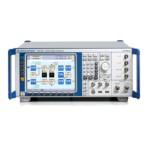
® Preparing for Use R&S SMU200A Front Panel Tour Fig. 2-1: Front panel view 2.1.1 Utility Keys The keys to the left of the display cause the R&S SMU to return to a definite instrument state and provide information on the instrument and assistance. For more information refer to chapter "Instrument Settings"... -
Page 30: Standby Leds And Standby Key
® Preparing for Use R&S SMU200A Front Panel Tour HELP Displays context-sensitive help text. 2.1.2 Standby LEDs and Standby Key The standby LEDs and the ON/STANDBY key are located in the bottom left corner of the front panel. The ON/STANDBY key toggles the instrument between standby and ready state (indi- cated by the standby LEDs). -
Page 31: Setup Keys
® Preparing for Use R&S SMU200A Front Panel Tour 2.1.4 Setup Keys The keys to the right of the display set parameters, select views and control the windows. 2.1.4.1 Keys for Setting Paramters These keys provide direct access to the settings in the header of the instrument and can be used for fast changing the state of the modulation and the RF signal. -
Page 32: Display Keys
® Preparing for Use R&S SMU200A Front Panel Tour 2.1.4.2 Display Keys The keys on top of the rotary knob and the keys below the numeric key pad arrange different windows on the display. DIAGRAM Brings the block diagram to the foreground. Active menus are minimized. Active menus are indicated by the buttons in the "Winbar". -
Page 33: Keypad For Data Entry
® Preparing for Use R&S SMU200A Front Panel Tour 2.1.5 Keypad for data entry The keys in the data entry keypad are used to enter alphanumeric data and units. Data entry keys are only enabled while the cursor is placed on a data input field in a dialog. -
Page 34: Rotary Knob And Navigation Keys
® Preparing for Use R&S SMU200A Front Panel Tour ● In a dialog box, selects the default or focused button. ● In a dialog box, activates the edit mode for the focused area, if available. ● In a dialog box, activates or deactivates the selected option of the focused area, if the edit mode is active. - Page 35 ® Preparing for Use R&S SMU200A Front Panel Tour ● chapter "Baseband Input Settings Menu" in the Operating Manual. DATA Signal for Path A only. Input for external serial data signal in case of digital modulation. Output for serial data signal in case of digital modulation. For more information see: ●...
-
Page 36: Rear Panel Tour
® Preparing for Use R&S SMU200A Rear Panel Tour USB (universal serial bus) interfaces of type A (host USB). ● Connection of peripherals such as mouse or keyboard ● Connection of memory stick for file transmission ● Firmware update Note: Another USB interface type A (host USB) and a USB interface type B (device USB for data transmission) are available on the rear panel. -
Page 37: Description Of The Connectors
® Preparing for Use R&S SMU200A Rear Panel Tour Fig. 2-2: Rear panel view 2.2.1 Description of the Connectors (path A only) Output for internal LF modulation generator signal. See also data sheet and Operating Manual, section "LF Generator and LF Output". MARKER 1B Output for user-programmable marker signal 1 of path B for triggering and control of external devices. - Page 38 ® Preparing for Use R&S SMU200A Rear Panel Tour AC SUPPLY AND POWER SWITCH When the R&S SMU is connected to the AC supply, it automatically sets itself to the correct range for the applied voltage (range: see type label). There is no need to set the voltage manually or change fuses.
- Page 39 ® Preparing for Use R&S SMU200A Rear Panel Tour IEC 625/IEEE 488 IEC-bus (IEEE 488) interface for remote control of the instrument. See also c hapter A.1, "GPIB Bus Interface", on page 119 and chapter "Remote Control Basics" in the Operating Manual. Note: In order to avoid electromagnetic interference (EMI) caused by open lines, always terminate any connected IEC-bus cable with an instrument or a controller.
- Page 40 ® Preparing for Use R&S SMU200A Rear Panel Tour BASEBAND DIGITAL IN/OUT Digital Interface: ● Input for external digital I/Q signal (BBIN) in case of digital modulation (option R&S SMU-B17, Baseband Input (digital/analog)). ● Output of the digital I/Q signal (BBOUT) (option R&S SMU-B18 Digital I/Q Out). LAN CONNECTOR Ethernet interface ●...
-
Page 41: Putting Into Operation
® Preparing for Use R&S SMU200A Putting into Operation Note: With exception of the Clock Out signal, the signals for triggering and control apply for both paths. TRIGGER 1 / 2 TRIGGER 2: Input for external triggering of digital modulations and standards and ARB. TRIGGER 1: Rear Panel Connectors for path A (option R&S SMU-B81) and path B (option R&S SMU-B82). -
Page 42: Unpacking And Checking The Instrument
® Preparing for Use R&S SMU200A Putting into Operation Risk of instrument damage Before switching on the instrument, make sure that the following conditions are met: ● Instrument casing is closed and all fasteners are tightened. ● All fan openings are unobstructed and the airflow perforations are unimpeded. The minimum distance from the wall is 10 cm. -
Page 43: Placing Or Mounting The Instrument
® Preparing for Use R&S SMU200A Putting into Operation 2. Pull off the corrugated cardboard cover that protects the rear of the instrument. 3. Carefully unthread the corrugated cardboard cover at the front that protects the instrument handles and remove it. 4. -
Page 44: Connecting The Instrument To The Ac Supply
® Preparing for Use R&S SMU200A Putting into Operation Risk of instrument damage For rack installation, make sure that all fan openings are unobstructed and that the airflow perforations are unimpeded. This helps to prevent the instrument from overheating. 2.3.3 Connecting the Instrument to the AC Supply The R&S SMU is automatically adapted to the AC voltage supplied. -
Page 45: Standby And Ready State
® Preparing for Use R&S SMU200A Putting into Operation 2. In case the instrument is in standby mode, i.e. the yellow LED is on, press the ON/ STANDBY key to switch the instrument to ready state. 2.3.4.1 Standby and Ready state The ON/STANDBY key is located in the bottom left corner of the front panel. -
Page 46: Default Settings
® Preparing for Use R&S SMU200A Putting into Operation For more information, refer to section "Error Messages" in the Operating Manual. Additionaly to the automatic monitoring, the R&S SMU offers the following capabilities to ensure correct functioning: ● Internal Adjustments Press the SETUP key and select "System >... -
Page 47: Shutting Down The Instrument
® Preparing for Use R&S SMU200A Putting into Operation ● Uninterrupted level settings are switched off "Level Attenuator Mode" = AUTO ● Internal level control "Level ALC" = AUTO ● User correction "Level Ucor" = OFF ● "LF output State" = Off ●... -
Page 48: Connecting External Accessories
® Preparing for Use R&S SMU200A Connecting External Accessories Switching off the AC power You can leave the AC power on permanently to preserve your last instrument settings. Switching off is required only if the instrument must be completely disconnected from all power supplies. -
Page 49: Connecting A Monitor
® Preparing for Use R&S SMU200A Connecting External Accessories Connecting a memory stick or CD-ROM drive If installation of a memory stick or CD-ROM drive is successful, Windows XP informs you that the device is ready to use. The device is made available as a new drive ("D:") and is displayed under Windows Explorer. -
Page 50: Windows Operating System
® Preparing for Use R&S SMU200A Windows Operating System 3. S tart up the instrument. The green LED must be on. The external monitor is detected. The entire display of the instrument, containing the status bar, the block diagram and the winbar is displayed on the monitor additionally. -
Page 51: Service Packs And Updates
® Preparing for Use R&S SMU200A Windows Operating System For details and recommendations, see the R&S White Paper "Malware Protection" avail- able at http://www.rohde-schwarz.com/appnote/1EF73. 2.5.2 Service Packs and Updates Microsoft regularly creates security updates and other patches to protect Windows- based operating systems. -
Page 52: Setting Up A Network (Lan) Connection
® Preparing for Use R&S SMU200A Setting Up a Network (LAN) Connection Energy saving mode An energy saving mode is a default setting in the instrument. The hard disk switches to power-save mode if it is not accessed for 30 minutes. The energy-saving mode is exited by accessing the hard disk again. -
Page 53: Assigning The Ip Address
® Preparing for Use R&S SMU200A Setting Up a Network (LAN) Connection The use of hubs, switches, or gateways is not required, however, data transfer is still performed using the TCP/IP protocol. An IP address has to be assigned to the instru- ment and the computer, see ... -
Page 54: Using Computer Names
® Preparing for Use R&S SMU200A Setting Up a Network (LAN) Connection Assigning the IP address manually 1. Obtain the IP address and subnet mask for the R&S SMU and the IP address for the local default gateway from your network administrator. If necessary, also obtain the name of your DNS domain and the IP addresses of the DNS and WINS servers on your network. -
Page 55: Working With Directories
® Preparing for Use R&S SMU200A Setting Up a Network (LAN) Connection (available at http://www2.rohde-schwarz.com/file_13784/1EF73_0E.pdf) and the Win- dows XP help system. Note that changing firewall settings requires administrator rights. To transfer waveform files generated on an external PC using R&S WinIQSIM2, you have to disable the firewall. -
Page 56: Remote Access Via An External Controller
® Preparing for Use R&S SMU200A Remote Access via an External Controller Accessing the enabled directory 1. On the instrument, select "Start > Search > For Files and Folders > Printers, Com- puters > A Computer in the Network". 2. Enter the computer name and press ENTER to start the search. The computer and its name appears in the results list. - Page 57 ® Preparing for Use R&S SMU200A Remote Access via an External Controller Table 2-1: Remote access via an external computer Remote access via Installation of the additional appli- cation connec- on the instru- on the remote tion ment computer Web Browser required e.g.
-
Page 58: Using A Web Browser For Remote Access
® Preparing for Use R&S SMU200A Remote Access via an External Controller 2.7.1 Using a Web Browser for Remote Access The instrument can be remote-accessed via any Web browser, like Windows Internet Explorer or Mozilla Firefox for instance. To remote access the instrument via Web browser: 1. - Page 59 ® Preparing for Use R&S SMU200A Remote Access via an External Controller Risk of Unauthorized Access If the Windows Remote Desktop application is enabled on the instrument (go to "Start > Settings > Control Panel > System"), any user in the network who knows the computer name and login data can access it.
- Page 60 ® Preparing for Use R&S SMU200A Remote Access via an External Controller 3. Enter the user ID and password for the instrument (see also c hapter 2.5, "Windows Operating System", on page 33). 4. Click "Connect". When the connection has been set up, the instrument's screen appears on the remote computer.
-
Page 61: Remote Access Via Ultr@Vnc
® Preparing for Use R&S SMU200A Remote Access via an External Controller A bar showing the network address of the instrument is displayed on the screen which you can use to reduce, minimize or close the window. ● On the "General" tab: You can save the connection settings for later use using the "Save As"... - Page 62 ® Preparing for Use R&S SMU200A Remote Access via an External Controller See " Configuring Internet Connection Firewall for VNC Connection" on page 47. 4. Install the VNC Viewer on the remote computer with Windows operating system, see "...
- Page 63 ® Preparing for Use R&S SMU200A Remote Access via an External Controller b) In the "Additional Task Panel", enable all entries. A successful installation is indicated by a message. At the same time a warning is displayed stating that a password must be set. 4.
- Page 64 ® Preparing for Use R&S SMU200A Remote Access via an External Controller 5. Enter a password with a length of at least five digits. This password is used on the remote computer to access the instrument. Other set- tings may be changed according to the user-specific security requirements. After the installation the Ultr@VNC program is automatically started together with the operating system.
- Page 65 ® Preparing for Use R&S SMU200A Remote Access via an External Controller Installing the VNC Viewer on a Windows PC 1. Download the Ultr@VNC program form internet and follow the installation instruc- tions. Only the program component VNC Viewer is required. Note: The VNC Viewer program is included in the download for the installation of the Ultr@VNC program on the signal generator if "Full installation"...
- Page 66 ® Preparing for Use R&S SMU200A Remote Access via an External Controller Setting up the VNC connection on the Windows remote computer 1. Start VNC Viewer program component on the PC, select "VNC Server" and enter IP address of the instrument. 2.
-
Page 67: Using Virus-Protection Software
® Preparing for Use R&S SMU200A Using Virus-Protection Software 3. To terminate the connection on the external Windows PC, close the VNC Viewer program. The connection is terminated. The color of the VNC icon in the status bar of the instrument changes. -
Page 68: Lxi Configuration
® Preparing for Use R&S SMU200A LXI Configuration 2. In the "System" dialog, select the "Advanced > Performance > Settings > Change". 3. Enable "Drive D: [DATA]" and "System managed size", confirm with "Set" and close the dialog. The Symantec Antivirus program can be installed. 2.9 LXI Configuration LAN eXtensions for Instrumentation (LXI) is an instrumentation platform for measuring instruments and test systems that is based on standard Ethernet technology. - Page 69 ® Preparing for Use R&S SMU200A LXI Configuration ● Class C instruments are characterized by a common LAN implementation, including an ICMP ping responder for diagnostics. The instruments can be configured via a web browser; a LAN Configuration Initialize (LCI) mechanism resets the LAN con- figuration.
-
Page 70: Lxi Browser Interface
® Preparing for Use R&S SMU200A LXI Configuration Parameter Value TCP/IP Mode DHCP + Auto IP Address Dynamic DNS Enabled ICMP Ping Enabled Password for LAN configuration LxiWebIfc The LCI for the R&S SMU also resets the following parameters: Parameter Value Hostname <Instrument-specific host name>... -
Page 71: Lan Configuration
® Preparing for Use R&S SMU200A LXI Configuration The "Instrument Home Page" displays the device information required by the LXI stand- ard including the VISA resource string in read-only format. ► Press the "Inactive (press to toggle)" button to indicate the device. Pressing this button causes a LAN Status indicator on the instrument's home page to flash (if active). -
Page 72: Advanced Lan Configuration
® Preparing for Use R&S SMU200A LXI Configuration The "TCP/IP Mode" configuration field controls how the IP address for the instrument gets assigned (see also c hapter 2.6.2, "Assigning the IP Address", on page 36). For the manual configuration mode, the static IP address, subnet mask, and default gateway are used to configure the LAN. -
Page 73: Ping
® Preparing for Use R&S SMU200A LXI Configuration The "Advanced LAN Configuration" parameters are used as follows: ● The "Negotiation" configuration field provides different Ethernet speed and duplex mode settings. In general, the "Auto Detect" mode is sufficient. ● "ICMP Ping" must be enabled to use the ping utility. ●... - Page 74 ® Preparing for Use R&S SMU200A LXI Configuration Quick Start Guide 1007.9822.62 ─ 13...
-
Page 76: Getting Started
® Getting Started R&S SMU200A Brief Introduction to the Instrument's Concept 3 Getting Started This section helps you to get familiar with the R&S SMU and provides an introduction to the general concept of the instrument with a sample of the possible application fields as well as a description of the main blocks in the signal generation flow. - Page 77 ® Getting Started R&S SMU200A Brief Introduction to the Instrument's Concept The R&S SMU is equipped with an intuitive user interface. The central element of the display is the block diagram that shows the signal flow and processing from the left on the display to most right, i.e.
-
Page 78: Applications Of The Instrument
® Getting Started R&S SMU200A Applications of the Instrument Assistants simplify the completion of tables. After data entry in the assistant, the table is modified only after the "Accept" button has been pressed. Pressing the "Accept" button also stores the assistant data. For an introduction into the manual operating of the instrument, detailed operating instructions and an overview of menus refer to ... - Page 79 ® Getting Started R&S SMU200A Applications of the Instrument Internally generated I/Q signal The I/Q signal is generated internally in the R&S SMU. One or two baseband generators can be installed. The signals produced by the two generators can be added (possibly with frequency offset).
-
Page 80: Two Baseband Generators, One Rf Path
® Getting Started R&S SMU200A Applications of the Instrument Fig. 3-3: Operation of I/Q modulator with external I/Q signals applied to the baseband section Analog Wideband I/Q operation An external analog I/Q signal is directly applied to the I/Q modulator of the R&S SMU. In this mode, the entire bandwidth of the I/Q modulator can be utilized. -
Page 81: One Baseband Path And Two Rf Paths
® Getting Started R&S SMU200A Applications of the Instrument ● Generation of multicarrier signals with real time components ● Simulation of antenna diversity Fig. 3-5: Operation of R&S Signal Generator with two baseband generators and one RF path 3.2.3 One Baseband Path and Two RF Paths An examples of the possible applications of an instrument equipped with one baseband path and two RF paths is: ●... -
Page 82: Fully Equipped Two-Path Instrument
® Getting Started R&S SMU200A Baseband Section 3.2.4 Fully Equipped Two-Path Instrument Examples of the possible applications of a fully equipped two-path instrument are: ● Generation of a wanted signal and an interfering signal for receiver tests ● Generation of multicarrier signals with extremely wide bandwidth (>80 MHz) ●... - Page 83 ® Getting Started R&S SMU200A Baseband Section One or two baseband generators can be fitted in an R&S SMU and operated separately. Signals from the baseband generators can be routed from path A to B and vice versa, and added (possibly with frequency offset). The option Baseband Generator contains real time Custom Digital Modulation and ARB.
-
Page 84: Description Of Individual Diagram Blocks Of The Baseband Section
® Getting Started R&S SMU200A Baseband Section Software option R&S SMU-B71 comprises the 3GPP dynamic fading configurations moving propagation and birth-death propagation as well as the fine delay fading config- urations offering enhanced delay resolution. Digital output module (option R&S SMU-B18) The R&S SMU can be equipped with a standardized digital I/Q interface (LVDS) for online transfer of digital I/Q data. - Page 85 ® Getting Started R&S SMU200A Baseband Section Baseband B block Configures the second baseband source (if installed). The block is displayed only if the instrument contains two baseband generators. Depending on the installed software option, various digital standards, user-configured digital real time modulation or the built- in waveform generator (ARB) can be selected.
-
Page 86: Rf Section
® Getting Started R&S SMU200A RF Section BERT block In this block an integrated bit and block error rate tester can be set. The bit error tester makes it possible to evaluate a signal demodulated and decoded by a DUT by measuring the bit error rate. - Page 87 ® Getting Started R&S SMU200A RF Section I/Q Mod A block The (first) I/Q modulator is configured in this block. Also the Analog Wideband I/Q mode can be selected here, which allows external I/Q signals to be directly applied to the I/Q modulator, i.e.
-
Page 88: Example Of Setup
® Getting Started R&S SMU200A Example of Setup Note: For modulation modes that can be simultaneously used, refer to the R&S SMU data sheet. RF/A Mod B In this block, settings are made for analog modulation and RF parameters of path B. This block is displayed only if a second RF path is installed. - Page 89 ® Getting Started R&S SMU200A Example of Setup a) Turn the rotary knob and select the "Baseband A" block. b) Press the rotary knob to open the menu where the digital modulation can be selected (different modulation modes are available depending on the options installed).
- Page 90 ® Getting Started R&S SMU200A Example of Setup c) Turn the rotary knob and highlight "Custom Digital Mod...". Press the rotary knob to open the "Custom Dig. Mod." dialog. d) Turn the rotary knob to select parameter "Symbol Rate", press the rotary knob to allow editing and enter the preffered symbol rate with the aid of the numeric key- pad and the unit keys.
- Page 91 ® Getting Started R&S SMU200A Example of Setup e) Turn the rotary knob to select parameter "Coding". Press the button to open the selection list. Turn the rotary knob to select "Off" and press the knob to activate the selected item.
- Page 92 ® Getting Started R&S SMU200A Example of Setup g) Finally, select "State" and press the rotary knob to switch on the digital modula- tion. h) Press the DIAGRAM key to display the complete block diagram. To indicate the active state, the "Baseband" block is displayed in blue. Quick Start Guide 1007.9822.62 ─...
- Page 93 ® Getting Started R&S SMU200A Example of Setup The entry in the Winbar indicates that the "Custom Dig. Mod." menu is still open in the background. To display the menu in the foreground, press the softkey below the button in the "Windbar".
- Page 94 ® Getting Started R&S SMU200A Example of Setup 4. Select graphics display of I/Q signal a) Turn the rotary knob to select the "Graphics" block and open the respective menu. b) Select "State On" with the rotary knob to activate display of the I/Q diagram. Quick Start Guide 1007.9822.62 ─...
-
Page 96: Manual Operation
® Manual Operation R&S SMU200A Key Features 4 Manual Operation The R&S SMU can be operated intuitively either via the interactive block diagram or via a menu tree. All menus are in the form of windows that can be operated in the same way. Rotary knob, keys and softkeys, or alternatively a mouse, allow direct and therefore con- venient access to entries and settings. - Page 97 ® Manual Operation R&S SMU200A Key Features +T) key. The menus of the highlighted function blocks can be called by pressing the ENTER key. – Example: The "Baseband" block contains all menus required for baseband signal configu- ration. In this block all digital standards and the digital modulation can be selected. ●...
- Page 98 ® Manual Operation R&S SMU200A Key Features Operation is possible via front-panel keys, an external keyboard and the mouse. How- ever, most of the settings can be easily made with the rotary knob: ● Turning the rotary knob shifts the entry focus to the target element. ●...
- Page 99 ® Manual Operation R&S SMU200A Key Features Help functions for user support Numerous help functions support the user in signal configuration. ● Value ranges The valid setting range is displayed for each numeric parameter. This requires a short wait after activation of the entry field. The range is then displayed automatically after a few seconds.
-
Page 100: Display
® Manual Operation R&S SMU200A Display Graphics editor for definition of control signals Control signals are also graphically configured. Graphical display of output signal in a diagram The output signal can be graphically displayed in a number of diagrams. This allows a fast check of signal characteristics. -
Page 101: Settings Displayed In The Header Section
® Manual Operation R&S SMU200A Display ● The block diagram shows the instrument configuration, the signal characteristic as well as the inputs and outputs used and permits interactive operation via graphics elements. Active menus and graphs are displayed on top of the block diagram. ●... -
Page 102: Status Information And Messages
® Manual Operation R&S SMU200A Display 4.2.2 Status Information and Messages The status information and messages are displayed in the header section of the screen. The messages differ with respect to their importance (errors, warnings, info) and the time of their appearance (brief and permanent messages). They require different treatment by the user. -
Page 103: Permanent Messages
® Manual Operation R&S SMU200A Display 4.2.2.4 Permanent Messages Permanent messages are displayed if an error occurs that impairs further instrument operation, e.g. a hardware fault. The error signalled by a permanent message must be eliminated before correct instrument operation can be ensured. The message is displayed until the error is eliminated. -
Page 104: Block Diagram
® Manual Operation R&S SMU200A Display This button is available only if the history of the messages is displayed. SCPI command: SYST:ERR:ALL? Each time a SYST:ERR:ALL? query is sent, the error queue is returned and at the same time cleared. History Calls the list of all messages that have occurred since instrument switch-on. -
Page 105: Signal Flow And Input/Output Symbols In The Block Diagram
® Manual Operation R&S SMU200A Display In all function blocks where the signal flow can be influenced, the top menu level for setting signal routing parameters is offered. Example: Baseband block In this block, the digital modulation signal, the digital standards, arbitrary waveform gen- eration and multicarrier CW are set. -
Page 106: Winbar And Softkeys
® Manual Operation R&S SMU200A Display ● The baseband signal is indicated by a three line arrow, the I- and Q-components of the signal by a single-line arrow. ● Addition of signals is indicated by the summation sign. ● Connections are indicated by a "solder point". ●... -
Page 107: Graphical Display Of Output Signal Characteristics
® Manual Operation R&S SMU200A Display Working with menus and dialog boxes is described in c hapter 4.3, "Accessing Dia- logs", on page 91; the setting of parameters in c hapter 4.4, "Setting Parame- ters", on page 92. The menus are in Windows format. -
Page 108: Accessing Dialogs
® Manual Operation R&S SMU200A Accessing Dialogs To access the "Graphics Settings" dialog for selecting the graphics display of the output signal, select the "Graphics" function block in the diagram or press the MENU (CTRL+M) key. Operation of the graphics windows is analogous to menu operation. The menu and the individual graphical displays are described in "Graphics Display"... -
Page 109: Setting Parameters
® Manual Operation R&S SMU200A Setting Parameters Activating the Windbar ► Use the WINBAR (CTRL+W) key to toggle the cursor between a button of the "Win- bar" and the block diagram. The button that was active last in the Winbar is highlighted. Closing an active menu ►... -
Page 110: Working With The Cursor
® Manual Operation R&S SMU200A Setting Parameters the GPIB-bus address. In the "File" dialog, files and lists are managed; in the "Hcopy" dialog, printout is configured and hardcopies can be made. These menus can only be called with the SETUP (CTRL+E), FILE (CTRL+S) and HCOPY (CTRL+Y) keys. Frequency and level are directly set in the header area of the display using the FREQ and LEVEL keys. -
Page 111: Selecting A Control Element
® Manual Operation R&S SMU200A Setting Parameters ● Quits the edit mode, if the edit mode is active. ● Switches between different entry fields of a menu. ● Shifts the entry cursor from the header display to the previously active menu, or to the previously highlighted block in the block diagram if no menu is active. - Page 112 ® Manual Operation R&S SMU200A Setting Parameters Numeric and alphanumeric values can either be newly entered or the existing value can be changed. Incorrect entries are cleared with the BACKSPACE key. Entering a new numerical value 1. Select the parameter. 2.
-
Page 113: Working With Units
® Manual Operation R&S SMU200A Setting Parameters Editing an alphanumerical value An existing value, e.g. a file name, can be changed in the insert mode (see example) or in the overwrite mode. 1. Select the paramter and activate the editing mode. 2. -
Page 114: Selecting A Value From A List
® Manual Operation R&S SMU200A Setting Parameters Changing a unit To subsequently change a unit, i.e. after the entry has been terminated and when the editing mode is not active, use one of the following alternatives: 1. Press a UNIT key on the front panel. 2. -
Page 115: Restoring The Previous Value
® Manual Operation R&S SMU200A Setting Parameters Confirming multiple values In some cases, like for instance when configuring the carriers for a multicarrier CW signal in a carrier table, it is useful first to enter few values and to confirm them together. Such settings require additional confirmation. -
Page 116: Editors
® Manual Operation R&S SMU200A Editors A confirmation query is displayed. 2. Confirm with "OK" to abort the changes. Select "Cancel" to return to the dialog. The previous selected settings are displayed. Restoring values after an extended calculation has been started Calculation and setting might require different period of time. - Page 117 ® Manual Operation R&S SMU200A Editors Editing list mode data lists 1. To access a list editor and open an existing data list for editing, use the cursor keys to select the associated button "Edit User Correction Data..." or "Edit List Mode Data..."...
-
Page 118: Working With Data Editor
® Manual Operation R&S SMU200A Editors Creating a new list mode data list A new list can be created under a new name either by generating a blank file in the "File Select" menu (see section c hapter 4.7, "File Management", on page 108) or by changing an existing list which will then be saved under a new name. -
Page 119: Working With Control And Marker List Editor
® Manual Operation R&S SMU200A Editors 3. To delete a value, use the arrow keys to mark the bit that follows the value to be deleted. Press the INSERT key to activate the insert mode. Values cannot be deleted in the overwrite mode. - Page 120 ® Manual Operation R&S SMU200A Editors Example: The following figure shows the "Slot Marker Definition Editor" of the "GSM/EDGE" dialog as an example. The upper area displays the signal for which the marker signals are to be defined. On the left side, the available signals (marker and control signals) are listed and colour-coded.
- Page 121 ® Manual Operation R&S SMU200A Editors 2. To access the slot marker list editor (e.g. "Slot Marker") and open an existing list for editing, use the arrow keys to select "GSM/EDGE > Burst Editor > Slot Marker Def- inition". Editing an existing control or marker list 1.
- Page 122 ® Manual Operation R&S SMU200A Editors Enter the file name in the "Create File" dialog and select the directory (see c hap- ter 4.7.1, "File Select Dialog", on page 109). Handling of Ramps 1. Set a new ramp Use the arrow keys or use the parameter "Cursor Position" to move the cursor to the position where the ramp is to be inserted.
-
Page 123: How To Use The Help System
® Manual Operation R&S SMU200A How to Use the Help System Select the "Edit Table..." button and define the positions and states of the ramps for the selected marker. Confirm the entries with "Accept". 5. Preset a marker signal Select the "Preset" button to preset the marker signal. The ramps of the selected marker are adjusted according to the selected "Preset Type". - Page 124 ® Manual Operation R&S SMU200A How to Use the Help System Contents of the help dialog box The help dialog box contains two main areas: ● "Contents" - contains a table of help contents ● "Topic" - contains a specific help topic The help system provides additionally an "Index"...
-
Page 125: File Management
® Manual Operation R&S SMU200A File Management 5. Press the ENTER key to display the help topic. The corresponding help topic is displayed. Closing the help window ► Press the HELP (F1) key. 4.7 File Management The R&S SMU uses files to save all instrument data, i.e. system and user data. The user data includes saved instrument settings, data for the different digital standards, lists for the List mode and the user correction as well as the waveforms for the arbitrary waveform generator. -
Page 126: File Select Dialog
® Manual Operation R&S SMU200A File Management Waveforms are generated externally (e.g. by means of the R&S WinIQSIM2 program that is supplied together with the optional Baseband Generator R&S SMU-B10) and can be loaded in the "Arbitrary Waveform Generation" dialog. Softkeys are assigned to some of the functions and can be used for convinient operation. - Page 127 ® Manual Operation R&S SMU200A File Management The available drives and directories and the files of the selected directory are displayed. The currently selected path is displayed above the window. Only the relevant files without file extensions are displayed. If the area is opened several times, the path last selected is displayed.
-
Page 128: File Manager
® Manual Operation R&S SMU200A File Management To create a new file, use the "Save Settings" functionality, i.e. specify file name and directory and save the file. The created file is empty; it must be filled with the necessary values in the individual editor. -
Page 129: Extensions For User Files
® Manual Operation R&S SMU200A File Management contains a file with the same name, a confirmation query is displayed to confirm overwriting of this file. Perform the similar steps and cut/copy/rename/delete the file. Tip: The operation corresponds to the Windows concept. 4. - Page 130 ® Manual Operation R&S SMU200A File Management Function/Digital List type Contents File suffix Standard Slot User-defined slot data *.gsm_slu Frame User-defined frame data *.gsm_fu Slot Higher symbol rate slot *.gsm_hslu Frame Higher symbol rate frame *.gsm_hfu "Bluetooth" Bluetooth Set- Complete setting of the Bluetooth menu *.bto tings "TETRA"...
-
Page 131: Legend Of Front-Panel Controls
® Manual Operation R&S SMU200A Legend of Front-Panel Controls Function/Digital List type Contents File suffix Standard Settings GPS UTC File *.rs_utc *.rs_acq "FM-Stereo" Settings Complete setting of the FM-Stereo menu *.fmstereo Settings FM-Stereo Group Type Settings *.fm_gt Settings FM-Stereo Group Hex Type Settings *.fm_ghex Waveform File Waveform File *.wav... - Page 132 ® Manual Operation R&S SMU200A Legend of Front-Panel Controls Front-panel key Key of PC keyboard Function +/- / A<->a - / (shift+) a—z Enters the sign. Switches between upper-case and lower-case let- ters. 0-9 / a...z CTRL+ 0-9 / a...z CTRL Enters the number/letter.
-
Page 133: Front Panel Key Emulation
® Manual Operation R&S SMU200A Legend of Front-Panel Controls Front-panel key Key of PC keyboard Function RF ON/OFF CTRL + R Switches the RF output signal on/off. "RF OFF" is indicated in the status line. Both RF output signals are always deactivated in the case of two-path instruments. - Page 134 ® Manual Operation R&S SMU200A Legend of Front-Panel Controls Quick Start Guide 1007.9822.62 ─ 13...
-
Page 136: A Hardware Interfaces
® Hardware Interfaces R&S SMU200A GPIB Bus Interface A Hardware Interfaces This section covers hardware related topics, like pin assignment of the GPIB bus inter- face, monitor and AUX I/O connectors. The remote control interfaces are described in detailes in the Operating Manual, section "Remote Control Basics". -
Page 137: Aux I/O Connector
® Hardware Interfaces R&S SMU200A AUX I/O Connector SRQ (Service Request): active LOW enables the connected device to send a service request to the controller. REN (Remote Enable): active LOW permits switchover to remote control. EOI (End or Identify): has two functions in connection with ATN: –... - Page 138 ® Hardware Interfaces R&S SMU200A AUX I/O Connector Table 1-2: Pin assignment of the AUX I/O Connector connector Signal Description Ground ⊥ 1 .. 25 Ground LEV ATT Signal input/output for controlling the level attenuation. For two-path instruments, the signal for Path B can be applied to one of the USER interfaces.
-
Page 139: Monitor Connector (Monitor)
® Hardware Interfaces R&S SMU200A Monitor Connector (MONITOR) Signal Description BITCLK Output Bit clock for internal mode. For two-path instruments, the signal for Path B can be applied to one of the USER interfaces. USER 2 USER input/output which can be configured for various purposes. SYMBCLK Symbol clock output for internal mode. - Page 140 ® Hardware Interfaces R&S SMU200A BERT Connector Fig. 1-2: BERT circuit diagram Quick Start Guide 1007.9822.62 ─ 13...
-
Page 142: Index
® Index R&S SMU200A Index USB type B ..............22 USER ................ 23 Abort button ..............99 Control bus ..............119 Abort calculation .............. 99 Controller, external ............39 Access denied ..............90 Cursor keys ..............17 AC supply ................ 21 CW Mode .............. - Page 143 ® Index R&S SMU200A Cursor key ..............17 Login ................34 DIAGRAM ..............15 service packs ............34 ENTER ..............16 Output ESC ................15 BITCLK ..............122 FILE ................14 BURST ..............121 FREQ ................ 14 DATA ..............121 HCOPY ..............
- Page 144 ® Index R&S SMU200A Winbar ................89 Windows XP ..............33 access ..............34 Quick Start Guide 1007.9822.62 ─ 13...
Need help?
Do you have a question about the 1141.2005.02 and is the answer not in the manual?
Questions and answers