Sign In
Upload
Manuals
Brands
Rohde & Schwarz Manuals
Portable Generator
SMV03
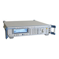
Rohde & Schwarz SMV03 Signal Generator Manuals
Manuals and User Guides for Rohde & Schwarz SMV03 Signal Generator. We have
1
Rohde & Schwarz SMV03 Signal Generator manual available for free PDF download: Operating Manual
Rohde & Schwarz SMV03 Operating Manual (299 pages)
SIGNAL GENERATOR
Brand:
Rohde & Schwarz
| Category:
Portable Generator
| Size: 5 MB
Table of Contents
Table of Contents
5
Putting into Operation
45
General Instructions
45
Unpacking the Instrument
45
Setting up the Instrument
46
Cleaning the Outside and Storing
46
Supply Voltage
47
How to Ensure EMC
47
Power Fuses
47
Switching On/Off the Instrument
47
Initial Status
47
RAM with Battery Back
48
Preset Setting
48
Functional Test
48
Mounting into a 19" Rack
48
Explanation of Front and Rear Panel
49
Elements of the Front Panel
49
Fig. 1-1 Front Panel View
49
Elements of the Rear Panel
54
Fig. 1-2 Rear Panel View
54
Fig. 1-2 Rear Panel View
55
Short Tutorial
57
Sample Setting for First Users
57
Fig. 2-1 Display for am Setting
59
Fig. 2-2 Display for Pattern Setting
61
Manual Operation
63
Design of the Display
63
Fig. 3-1 Design of the Display
63
Basic Operating Steps
64
Calling the Menus
64
Fig. 3-2 Modulation - am Menu
64
Selection and Change of Parameters
65
Quick Selection of Menu (QUICK SELECT)
66
Use of [FREQ] and [LEVEL] Keys
67
Use of [RF ON/OFF] and [MOD ON/OFF]
67
Changing Unit of Level
67
Correction of Input
68
List Editor
69
Fig. 3-3 Level - Ucor Menu
69
Select List
70
Delete List
70
Fig. 3-4 Select List Window
70
Fig. 3-5 Delete List Window
70
Edit List
71
Fig. 3-6 Edit Function Insert
72
Fig. 3-7 Fill Editing Function
73
Fig. 3-8 Edit Editing Function
74
Fig. 3-9 Delete Editing Function
75
Storing/Calling of Instrument Settings
76
Menu Summary for R&S SML
77
Menu Summary for R&S SMV03
78
Instrument Functions
79
RF Frequency
79
Extended Divider Range
79
Fig
79
Fig. 4-2 Typical Setups with Frequency Offset
80
RF Level
81
Level Offset
83
Non-Interrupting Level Setting
83
Fig. 4-4 Typical Setup with Level Offset
83
Switching On/Off Automatic Level Control (ALC)
84
User Correction (Ucor)
85
[RF ON/OFF] Key
86
Fig. 4-8 Ucor - Level Menu
86
Modulation - General
87
Modulation Sources
87
Simultaneous Modulation
88
Mutual Switch-Off of Modulation Types
88
[MOD ON/OFF] Key
88
Analog Modulations
89
Amplitude Modulation
89
Frequency Modulation
90
Phase Modulation
91
Pulse Modulation (Option R&S SML-B3)
92
Fig. 4-13 Signal Example 1: Single Pulse, Pulse Mode = Auto Trig
94
Fig. 4-14 Signal Example 2: Double Pulse, Pulse Mode = Ext Trig, Slope = Pos
94
Fig. 4-15 Signal Example 3: Single Pulse, Pulse Mode = Ext Gated
94
Stereo Modulation (Option R&S SML-B5)
95
Fig. 4-16 Modulation - Stereo Menu (Preset Setting), Equipped with Option R&S SML-B5
95
Vector Modulation (R&S SMV03 Only)
121
Fig. 4-15 Example: Vector Modulation
121
Fig. 4-16 VECTOR MOD Menu (Preset Settings) R&S SMV03
121
I/Q Impairment
123
LF Generator
124
LF Output
124
Fig. 4-17 LF Output Menu (Preset Setting)
124
PULSE/VIDEO Output
125
Sweep
127
Setting the Sweep Range (Start Freq, Stop Freq, Center Freq, Span)
127
Selecting Linear or Logarithmic Sweep (Spacing Lin, Log)
128
Operating Modes (Mode)
128
Sweep Inputs
129
Run
129
RF Sweep
129
Fig. 4-19 Sweep - Freq Menu
129
Level Sweep
131
Fig. 4-20 Sweep - Level Menu
131
LF Sweep
132
Utilities
133
Display
133
Fig. 4-22 Utilities Menu
133
Fig. 4-23 Utilities - Display Menu
133
System
134
Fig. 4-24 Utilities - System Menu
134
Fig. 4-25 Utilities - System - GPIB - Address Menu
134
Internal/External Reference Frequency (Refosc)
137
Phase of the Output Signal
138
Passwords for Accessing Protected Functions (Protect)
139
Calibration (Calib)
140
Table 4-1 Overview of Internal Calibration Routines
140
Display of Module Versions (Diag - Config)
141
Display of Voltages of Test Points (Diag - Tpoint)
142
Display of Service Data (Diag - Param)
143
Test
144
Assigning Modulations to the [MOD ON/OFF] Key (Modkey)
145
Setting the Sweep Blank Time
146
Status
147
Remote Control - Basic Information
149
Brief Instructions
149
IEC/IEEE Bus
149
RS-232-C Interface
150
Switchover to Remote Control
151
Remote Control Via IEC/IEEE Bus
151
Remote Control Via RS-232-C Interface
152
Messages
153
Interface Messages
153
Device Messages (Commands and Device Responses)
153
Structure and Syntax of Device Messages
154
Introduction to SCPI
154
Structure of Commands
154
Structure of Command Lines
157
Responses to Queries
157
Parameters
158
Overview of Syntax Elements
160
Instrument Model and Command Processing
161
Input Unit
161
Command Recognition
162
Data Set and Instrument Hardware
162
Status Reporting System
162
Output Unit
163
Command Sequence and Command Synchronization
163
Table 5-1 Synchronization by Means of *OPC, *OPC? and *WAI
163
Status Reporting System
164
Structure of an SCPI Status Register
164
Overview of Status Registers
166
Description of Status Registers
167
Table 5-2 Meaning of the Bits Used in the Status Byte
167
Table 5-3 Meaning of the Bits Used in the Event Status Register
168
Use of Status Reporting System
170
Reset Values of Status Reporting System
172
Interfaces
173
IEC/IEEE-Bus Interface
173
RS-232-C Interface
176
Remote Control - Description of Commands
179
Notation
179
Common Commands
181
Table 6-1 Common Commands
181
Table 6-2 Device Response to *OPT
182
Abort System
184
Calibration System
184
Diagnostic System
186
DISPLAY System
188
Memory System
189
Output System
189
Source System
191
Source:am Subsystem
191
Source:correction Subsystem
193
Source:DM Subsystem (R&S SMV03)
195
Source:fm Subsystem
197
Source:frequency Subsystem
199
Source:phase Subsystem
202
Source:pm Subsystem
203
Source:power Subsystem
205
Source:pulm Subsystem
208
Source:pulse Subsystem
209
Source:roscillator Subsystem
211
Source:stereosubsystem
212
Source:sweep Subsystem
216
Source2 System
219
Source2:Frequency Subsystem
219
Source2:Sweep Subsystem
221
Status System
223
System System
224
TEST System
227
Trigger System
228
UNIT System
230
List of Commands
231
Remote Control - Programming Examples
235
Including IEC-Bus Library for Quickbasic
235
Initialization and Default Status
235
Initiate Controller
235
Initiate Instrument
235
Transmission of Instrument Setting Commands
236
Switchover to Manual Control
236
Reading out Instrument Settings
236
Command Synchronization
237
Service Request
238
Maintenance
241
Storing and Packing
241
Exchanging the Lithium Battery
241
Error Messages
243
List of Error Messages
243
SCPI-Specific Error Messages
244
R&S SML / R&S SMV03-Specific Error Messages
248
Possible Error Sources
250
Performance Test
251
General
251
Table 10-1 Maximum Frequencies
251
Measuring Equipment and Accessories
252
Table 10-2 Measuring Equipment and Accessories
252
Table 10-5 Measuring Equipment and Accessories
252
Test Setups
253
Standard Test Setup
253
Test Setup for Setting Time
253
Test Setup for SSB Phase Noise
254
Test Setup for Output Reflection Coefficient
254
Test Setup for Pulse Modulator Option R&S SML-B3
255
Test Setup for Stereo Coder Option R&S SML-B5
255
Test Sequence
256
Display and Keyboard
256
Frequency
256
Table 10-3 Measuring the Frequency Setting Time
257
Reference Frequency
258
Spectral Purity
259
Residual
262
Level
263
Overvoltage Protection
268
Internal Modulation Generator
268
Amplitude Modulation
269
AM Total Harmonic Distortion
271
Frequency Modulation
272
FM Total Harmonic Distortion
273
Phase Modulation
276
Pulse Modulation (Option R&S SML-B3)
278
Stereo Modulation (Option R&S SML-B5)
280
Performance Test Report
284
Performance Test - Extension for R&S SMV03
288
Preliminary Remark
288
Measuring Equipment and Accessorie
288
Test Setups
290
Standard Test Setup
290
Test Sequence
291
Settig Time
291
Spectral Purity
291
Level
293
Vector Modulation
294
Performance Test Report
299
Table 10-4 Performance Test Report
299
Table 10-6 Performance Test Report
299
Advertisement
Advertisement
Related Products
Rohde & Schwarz SMA100B
Rohde & Schwarz SMAB-B85
Rohde & Schwarz SMAB-K24
Rohde & Schwarz SMAB-K721
Rohde & Schwarz SMAB-K723
Rohde & Schwarz SMJ-K52
Rohde & Schwarz SMCVB-K511
Rohde & Schwarz SMAB-B131
Rohde & Schwarz R&S SMBVB-K114
Rohde & Schwarz R&S SMW-K78
Rohde & Schwarz Categories
Measuring Instruments
Test Equipment
Portable Generator
Power Supply
Accessories
More Rohde & Schwarz Manuals
Login
Sign In
OR
Sign in with Facebook
Sign in with Google
Upload manual
Upload from disk
Upload from URL