Table of Contents
Advertisement
Quick Links
For spare parts drawings refer to the section " LIST OF COMPONENTS" enclosed to this manual.
• For any further information please contact your local dealer or call:
Phone (+39) 0522 647911 - Fax (+39) 0522 649760 - e-mail: Info@butler.it
1294-M015-2_B
LIBRAK240RTLD
LIBRAK240RTLCD
INSTRUCTION MANUAL
TRANSLATION FROM THE
GB
ORIGINAL INSTRUCTIONS
BUTLER ENGINEERING and MARKETING S.p.A. a s. u.
Via dell'Ecologia, 6 - 42047 Rolo - (RE) Italy
1294-M015-2_B
- Rev. n. 2 (11/2017)
Advertisement
Table of Contents

Related Manuals for Butler LIBRAK240RTLD


Summary of Contents for Butler LIBRAK240RTLD
- Page 1 • For any further information please contact your local dealer or call: BUTLER ENGINEERING and MARKETING S.p.A. a s. u. Via dell’Ecologia, 6 - 42047 Rolo - (RE) Italy Phone (+39) 0522 647911 - Fax (+39) 0522 649760 - e-mail: Info@butler.it 1294-M015-2_B - Rev. n. 2 (11/2017)
-
Page 2: Table Of Contents
1294-M015-0_B INSTRUCTION, USE AND MAINTENANCE MANUAL Page 2 of 52 LIBRAK240RTLD - LIBRAK240RTLCD SUMMARY SYMBOLS USED IN THE MANUAL AND 15.1.2 Entry of measures _________________21 15.2 User management _____________________24 ON THE MACHINE ________________________ 5 15.3 Unbalance measurement ______________24 1.0 GENERAL INTRODUCTION __________ 7 15.3.1 Indicative display of points where... - Page 3 1294-M015-0_B INSTRUCTION, USE AND Page 3 of 52 MAINTENANCE MANUAL LIBRAK240RTLD - LIBRAK240RTLCD 24.0 TECHNICAL DATA __________________ 48 28.0 FUNCTIONAL DIAGRAMS __________ 50 24.1 Dimensions ____________________________49 Table A - Electrical connection diagram _________________________51 25.0 STORING ___________________________ 50 Table B - Pneumatic connection diagram _________________________52 26.0 SCRAPPING ________________________ 50...
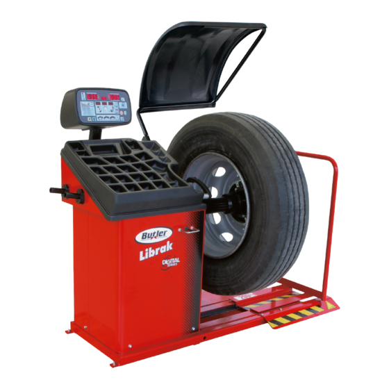
- Page 4 1294-M015-0_B INSTRUCTION, USE AND MAINTENANCE MANUAL Page 4 of 52 LIBRAK240RTLD - LIBRAK240RTLCD Fig. 1 1 – Weight holding bridge 2 – Control panel/led display 3 – Distance caliper 4 – Threaded shaft 5 – Lifting device 6 – Main switch 7 –...
-
Page 5: Symbols Used In The Manual And On The Machine
1294-M015-0_B INSTRUCTION, USE AND Page 5 of 52 MAINTENANCE MANUAL LIBRAK240RTLD - LIBRAK240RTLCD SYMBOLS USED IN THE MANUAL AND ON THE MACHINE Symbols Description Symbols Description Mandatory. Operations or jobs to Read instruction manual. be performed compulsorily. FORBIDDEN! Danger! Be particularly careful. - Page 6 1294-M015-0_B INSTRUCTION, USE AND MAINTENANCE MANUAL Page 6 of 52 LIBRAK240RTLD - LIBRAK240RTLCD INFORMATION PLATE LOCATION TABLE ♦ 999912380 99990758 999912940 999916311 • 99990114 999919050 999916980 999910050 999915570 B1541000 Code numbers of plates B1541000 Danger plate 99990114 Arrow plate 99990758...
-
Page 7: General Introduction
LIBRAK240RTLD - LIBRAK240RTLCD INTENDED USE SOME OF THE PICTURES AND/ OR DISPLAY SCREEN PAGES The machines of model LIBRAK240RTLD - PRESENT IN THIS MANUAL HAVE LIBRAK240RTLCD, and relative versions, are BEEN OBTAINED FROM PICTURES wheels balancing machines for trucks, projected to... -
Page 8: Safety Devices
1294-M015-0_B INSTRUCTION, USE AND MAINTENANCE MANUAL Page 8 of 52 LIBRAK240RTLD - LIBRAK240RTLCD SAFETY DEVICES GENERAL SAFETY RULES PERIODICALLY, AT LEAST MONTH- LY, CHECK THE INTEGRITY AND THE FUNCTIONALITY OF THE SAFETY AND PROTECTION DE- • Any tampering with or modification to the machine VICES ON THE MACHINE. -
Page 9: Packing And Mobilization For Transport
1294-M015-0_B INSTRUCTION, USE AND Page 9 of 52 MAINTENANCE MANUAL LIBRAK240RTLD - LIBRAK240RTLCD PACKING AND MOBILIZATION FOR OPERATORS MUST WEAR SUIT- TRANSPORT ABLE WORK CLOTHES, PROTEC- TIVE GLASSES AND GLOVES, AGAINST THE DANGER FROM THE SPRAYING OF DANGEROUS DUST, AND POSSIBLY LOWER BACK SUPPORTS FOR THE LIFT- ING OF HEAVY PARTS. -
Page 10: Unpacking
1294-M015-0_B INSTRUCTION, USE AND MAINTENANCE MANUAL Page 10 of 52 LIBRAK240RTLD - LIBRAK240RTLCD UNPACKING MOBILIZATION DURING UNPACKING, ALWAYS WEAR GLOVES TO PREVENT ANY INJURY CAUSED BY CONTACT THE LIFTING EQUIPMENT MUST WITHSTAND WITH PACKAGING MATERIAL A MINIMUM RATED LOAD EQUAL TO THE (NAILS, ETC.). -
Page 11: Working Environment Condi
1294-M015-0_B INSTRUCTION, USE AND Page 11 of 52 MAINTENANCE MANUAL LIBRAK240RTLD - LIBRAK240RTLCD WORKING ENVIRONMENT CONDI- TIONS The machine must be operated under proper condi- tions as follows: USE THE MACHINE IN A DRY AND AD - • temperature: 0° + 45° C EQUATELY LIT PLACE, POSSIBLY INDOORS •... -
Page 12: Machine Assembly
1294-M015-0_B INSTRUCTION, USE AND MAINTENANCE MANUAL Page 12 of 52 LIBRAK240RTLD - LIBRAK240RTLCD • Execute 4 holes with 10 mm diameter on the floor MACHINE ASSEMBLY by the holes on the bottom floor; After having freed the various components from the •... -
Page 13: Assembly Procedure
1294-M015-0_B INSTRUCTION, USE AND Page 13 of 52 MAINTENANCE MANUAL LIBRAK240RTLD - LIBRAK240RTLCD Assembly procedures Fig. 5 129401060 9.3.1 Fitting the shaft on the flange Screw the shaft with an Allen wrench (Fig. 6 ref. 1) on the flange (Fig. 6 ref. 2). -
Page 14: Electrical Connection
1294-M015-0_B INSTRUCTION, USE AND MAINTENANCE MANUAL Page 14 of 52 LIBRAK240RTLD - LIBRAK240RTLCD 10.0 ELECTRICAL CONNECTION FIT A TYPE-APPROVED (AS RE- PORTED BEFORE) PLUG TO THE EVEN THE TINIEST PROCEDURE MACHINE CABLE (THE GROUND OF AN ELECTRICAL NATURE WIRE IS YELLOW/GREEN AND... -
Page 15: Air Connection
1294-M015-0_B INSTRUCTION, USE AND Page 15 of 52 MAINTENANCE MANUAL LIBRAK240RTLD - LIBRAK240RTLCD 12.0 MULTIFUNCTION LED PANEL Fig. 8 The wheel balancers are equipped with a multi-function display panel with signal LEDs, together with a silk- screen representing the shape of a rim and the various available options. -
Page 16: Display And Leds Brightness Adjust
1294-M015-0_B INSTRUCTION, USE AND MAINTENANCE MANUAL Page 16 of 52 LIBRAK240RTLD - LIBRAK240RTLCD 12.1 DISPLAY and LEDs brightness adjust- Fig. 11 ment Press the keys indicated below to adjust DISPLAY and LEDs brightness. Keep key , pressed and, at the same time, press to increase brightness. -
Page 17: Wheel Assembly
13.2 Wheel assembly the wheel on the mandrel. 2. Place the support flange (Fig. 15 ref. 3) on the Only for LIBRAK240RTLD model mandrel (Fig. 15 ref. 1). 3. Fit the wheel (Fig. 15 ref. 2) with the inside of the 1. -
Page 18: Switching The Machine On And Off
INSTRUCTION, USE AND MAINTENANCE MANUAL Page 18 of 52 LIBRAK240RTLD - LIBRAK240RTLCD T H E G R I P- R I N G ( F I G. 1 5 - 1 5 REF. 5-9) MUST BE MOUNTED Key for MOTORCYCLE/CAR/TRUCK WITH THE TEETH OR DISCHARGE wheel cycle. -
Page 19: Wheel Balancing
1294-M015-0_B INSTRUCTION, USE AND Page 19 of 52 MAINTENANCE MANUAL LIBRAK240RTLD - LIBRAK240RTLCD 15.0 WHEEL BALANCING 15.1 Determination of wheel dimensions 15.1.1 Manual setting of wheel dimensions Both LEDs ALU-S will flash program The wheel balancers feature a graduated scale for the manual detection of the distance for weight fitting. - Page 20 1294-M015-0_B INSTRUCTION, USE AND MAINTENANCE MANUAL Page 20 of 52 LIBRAK240RTLD - LIBRAK240RTLCD • To make a measurement in STATIC mode (STAT): • To make a measurement in DYNAMIC mode (DYN): Press key to select STATIC balancing program. Press key to select DYNAMIC balancing pro- gram.
-
Page 21: Entry Of Measures
1294-M015-0_B INSTRUCTION, USE AND Page 21 of 52 MAINTENANCE MANUAL LIBRAK240RTLD - LIBRAK240RTLCD 15.1.2 Entry of measures Letter will appear on “D1” display to indicate • To make a measurement in static mode ST1-ST2: rim diameter value insert. The value on display “D2”... - Page 22 1294-M015-0_B INSTRUCTION, USE AND MAINTENANCE MANUAL Page 22 of 52 LIBRAK240RTLD - LIBRAK240RTLCD • To make a measurement in ALU-S mode: Press key to select ALU-S balancing program. The corresponding LED turns on. Weight application point Use keys to set the value read on the graduated scale on “D1”...
- Page 23 1294-M015-0_B INSTRUCTION, USE AND Page 23 of 52 MAINTENANCE MANUAL LIBRAK240RTLD - LIBRAK240RTLCD • To take a measurement in ALU-S1 and ALU-S2 • To take a measurement in ALU1, ALU2, ALU3 and modes: ALU4 modes: Press key until selecting ALU-S1 (LED ALU-...
-
Page 24: User Management
1294-M015-0_B INSTRUCTION, USE AND MAINTENANCE MANUAL Page 24 of 52 LIBRAK240RTLD - LIBRAK240RTLCD 15.2 User control function Wheel balancers can be used by 2 different users at the same time, pressing the “user” , key, selecting user 1 or 2. -
Page 25: Balancing Mode
1294-M015-0_B INSTRUCTION, USE AND Page 25 of 52 MAINTENANCE MANUAL LIBRAK240RTLD - LIBRAK240RTLCD 15.3.2 Balancing mode • Weights fitting at “6 o'clock”. The machine has the ability to perform the wheel bal- TO USE THIS MODE, THE REL- ancing (weights fitting) in 2 different ways:... -
Page 26: Dynamic Balancing
1294-M015-0_B INSTRUCTION, USE AND MAINTENANCE MANUAL Page 26 of 52 LIBRAK240RTLD - LIBRAK240RTLCD 15.3.3 Dynamic balancing 15.3.4 ALU-S procedure Dynamic balancing is a procedure that offsets the The ALU-S balancing is a procedure that offsets the wheel vibrations using 2 weights on different planes. -
Page 27: Static Balancing (Stat)
1294-M015-0_B INSTRUCTION, USE AND Page 27 of 52 MAINTENANCE MANUAL LIBRAK240RTLD - LIBRAK240RTLCD 15.3.5 Static balancing (STAT) 15.3.6 Positioning the correction weights on the wheel The STATIC balancing procedure is used to offset wheel vibrations using 1 weight on a single plane. An The weights must be positioned at the top part of the adhesive weight is used inside the rim. -
Page 28: Measuring The Unbalance With Auxil- Iary Programs
1294-M015-0_B INSTRUCTION, USE AND MAINTENANCE MANUAL Page 28 of 52 LIBRAK240RTLD - LIBRAK240RTLCD The fitting point has been found. Now the unbalance 15.4 Measuring the unbalance with auxil- can be corrected by fitting the necessary weight. iary programs The available functions allow to select the appropri- ate weight positions to be placed in different positions compared to the standard ones (dynamic unbalance). - Page 29 1294-M015-0_B INSTRUCTION, USE AND Page 29 of 52 MAINTENANCE MANUAL LIBRAK240RTLD - LIBRAK240RTLCD The ST1 function is a procedure that offsets wheel vibrations using a single weight with clip on a single plane positioned exactly at “12 o’ clock”. Enter the measurements (see Par. 15.1) and proceed as described in Par.
-
Page 30: Alu1 Procedure
1294-M015-0_B INSTRUCTION, USE AND MAINTENANCE MANUAL Page 30 of 52 LIBRAK240RTLD - LIBRAK240RTLCD 15.4.1 ALU1 procedure ALU1 balancing is a procedure that offsets the wheel vibrations using 2 weights on different planes. Adhesive weights are used on rim inner and outer edge, and is usually carried out on alloy rims. -
Page 31: Pax Mode
1294-M015-0_B INSTRUCTION, USE AND Page 31 of 52 MAINTENANCE MANUAL LIBRAK240RTLD - LIBRAK240RTLCD 15.4.2 PAX mode From the results page (see for example Fig. 27), press PAX mode is a special procedure specially devised to ; the entered measurements page will be balance wheels using the “PAX System ®”. - Page 32 1294-M015-0_B INSTRUCTION, USE AND MAINTENANCE MANUAL Page 32 of 52 LIBRAK240RTLD - LIBRAK240RTLCD The page shown in Fig. 31 will be displayed. IMMEDIATELY AFTER HAVING SELECTED THE ECO -WEIGHT PROCEDURE (SEE FIG. 31), YOU CAN KNOW IN ADVANCE THE TWO...
-
Page 33: Wheel Balancing In Motorbike Mode
1294-M015-0_B INSTRUCTION, USE AND Page 33 of 52 MAINTENANCE MANUAL LIBRAK240RTLD - LIBRAK240RTLCD 16.0 WHEEL BALANCING IN MOTORBIKE Balancing procedures are identical for both modes (car/motorbike). MODE By selecting motorbike mode, besides dynamic balanc- By enabling the “motorbike wheel balancing” function ing (see Par. - Page 34 1294-M015-0_B INSTRUCTION, USE AND MAINTENANCE MANUAL Page 34 of 52 LIBRAK240RTLD - LIBRAK240RTLCD TWO SMALLER WEIGHTS (55g) If necessary, press key again to select wheel IN- USING SPLIT PROCEDURE NER side, the LEDs close to the inner display D1 will turn on.
-
Page 35: Weights Hidden Behind Spokes Mode
1294-M015-0_B INSTRUCTION, USE AND Page 35 of 52 MAINTENANCE MANUAL LIBRAK240RTLD - LIBRAK240RTLCD 18.0 WEIGHTS HIDDEN BEHIND SPOKES Enter the correct number of spokes, increasing or de- MODE creasing it using keys . A minimum of 3 Adhesive correction weight positioning may not look at- spokes and a maximum of 20 can be entered. -
Page 36: Matching Procedure (Rim - Tyre Optimization)
1294-M015-0_B INSTRUCTION, USE AND MAINTENANCE MANUAL Page 36 of 52 LIBRAK240RTLD - LIBRAK240RTLCD 19.0 MATCHING PROCEDURE (Rim - Tyre Optimization) The “MATCHING” procedure offsets strong unbalance, reducing the weight quantity to be fitted on the wheel to achieve balancing. This procedure permits reducing unbalance as much as possible by offsetting the tyre unbalance with that of the rim. - Page 37 1294-M015-0_B INSTRUCTION, USE AND Page 37 of 52 MAINTENANCE MANUAL LIBRAK240RTLD - LIBRAK240RTLCD Position the reference mark on the rim in line with Make a reference mark on the rim and tyre, in line the arrow on the flange with the arrow on the flange...
-
Page 38: Calibration
1294-M015-0_B INSTRUCTION, USE AND MAINTENANCE MANUAL Page 38 of 52 LIBRAK240RTLD - LIBRAK240RTLCD 20.0 CALIBRATION - When the LEDs on the LEFT show that the position has been reached (see Par. 15.3.6) make the refer- From the opening program presentation page ence mark on RIM. -
Page 39: Zero Mandrel" Setting
1294-M015-0_B INSTRUCTION, USE AND Page 39 of 52 MAINTENANCE MANUAL LIBRAK240RTLD - LIBRAK240RTLCD 20.1 “Zero mandrel” setting 20.2 Weight measurement sensors calibra- tion (CAR mode) When the following symbols are shown on display screens D1 and D2 (see Chapt. 20.0): START FROM SELECTED "CAR"... - Page 40 1294-M015-0_B INSTRUCTION, USE AND MAINTENANCE MANUAL Page 40 of 52 LIBRAK240RTLD - LIBRAK240RTLCD Take the pliers of the automatic distance/diameter caliper and bring it to the rim edge Press key to perform wheel spin. These symbols will be shown on D1 and D2 displays:...
-
Page 41: Weight Measurement Sensors Calibra
1294-M015-0_B INSTRUCTION, USE AND Page 41 of 52 MAINTENANCE MANUAL LIBRAK240RTLD - LIBRAK240RTLCD 20.3 Weight measurement sensors calibra- After wheel spin, the following symbols will be shown on display screens D1 and D2: tion (TRUCK mode) START FROM SELECTED "TRUCK"... -
Page 42: User's Setting And Customiza- Tions
1294-M015-0_B INSTRUCTION, USE AND MAINTENANCE MANUAL Page 42 of 52 LIBRAK240RTLD - LIBRAK240RTLCD After wheel spin, the following symbols will be shown on display screens D1 and D2: Press key to confirm. The following symbols will be shown on D1 and D2 display screens:... -
Page 43: Setting Measurements Units For Rim Weight And Width/Diameter
1294-M015-0_B INSTRUCTION, USE AND Page 43 of 52 MAINTENANCE MANUAL LIBRAK240RTLD - LIBRAK240RTLCD 21.1 Setting measurements units for rim weight and width/diameter SOME OF THE PARAMETERS LISTED BELOW COULD NOT BE DISPLAYED FOR THIS TYPE OF MACHINE. The weight determining wheel unbalance can be indicated on the display in "gram" or "ounce" measurement unit. -
Page 44: Width Measurement Option Setting
1294-M015-0_B INSTRUCTION, USE AND MAINTENANCE MANUAL Page 44 of 52 LIBRAK240RTLD - LIBRAK240RTLCD “LED-LIGHT” function can be ENABLED or DISABLED VALUE 000 = Disabled Parameter 10* (LED LIGHT) VALUE 001 = Enabled “LASER BLADE” function can be ENABLED or DISABLED... -
Page 45: Setting Adhesive Weight Dimensions And Static Threshold Percentage
1294-M015-0_B INSTRUCTION, USE AND Page 45 of 52 MAINTENANCE MANUAL LIBRAK240RTLD - LIBRAK240RTLCD CAR = from 1 to 20 grams step 1 (from 0.05 to 1 ounce step 0.05) Parameter 21 (ALU PROGRAM TRUCK = from 10 to 200 grams step 10 (from 0.5 to 10 ounce step LOWER LIMIT) 0.5) -
Page 46: Error Signals
INSTRUCTION, USE AND MAINTENANCE MANUAL Page 46 of 52 LIBRAK240RTLD - LIBRAK240RTLCD 22.0 ERROR SIGNALS During wheel balancer operation, if wrong commands are given by the operator or device faults occur, an er- ror code or symbol may appear on the display screen D1. Press key to return to the previous program phase after remedying the fault. -
Page 47: Routine Maintenance
1294-M015-0_B INSTRUCTION, USE AND Page 47 of 52 MAINTENANCE MANUAL LIBRAK240RTLD - LIBRAK240RTLCD 23.0 ROUTINE MAINTENANCE To guarantee the efficiency and correct functioning of the machine, it is essential to carry out daily or weekly cleaning and weekly routine maintenance, as BEFORE CARRYING OUT ANY ROU- described below. -
Page 48: Technical Data
1294-M015-0_B INSTRUCTION, USE AND MAINTENANCE MANUAL Page 48 of 52 LIBRAK240RTLD - LIBRAK240RTLCD 24.0 TECHNICAL DATA LIBRAK240RTLD LIBRAK240RTLCD Wheel max. weight (Kg) Max. absorbed voltage (W) Power supply 230V 50/60 Hz 1 ph Balancing precision (g) Balancing speed (rpm) < 80 Min/max rim - machine distance 0 ÷... -
Page 49: Dimensions
1294-M015-0_B INSTRUCTION, USE AND Page 49 of 52 MAINTENANCE MANUAL LIBRAK240RTLD - LIBRAK240RTLCD 24.1 Dimensions Fig. 54 1301 1843... -
Page 50: Storing
1294-M015-0_B INSTRUCTION, USE AND MAINTENANCE MANUAL Page 50 of 52 LIBRAK240RTLD - LIBRAK240RTLCD 25.0 STORING 27.0 REGISTRATION PLATE DATA If storing for long periods disconnect the main power supply and take measures to protect the machine from dust build-up. Lubricate parts that could be damaged from drying out. -
Page 51: Diagram
8 – Power card kit 18 – Short flat cable 9 – Motor 19 – Display power supply cable 10 – Motor support ground cable LIBRAK240RTLD - LIBRAK240RTLCD WIRING CONNECTION 1294-M015-0_B DIAGRAM Page 51 of 52 Table N°A - Rev. 0... -
Page 52: Diagram
7 – Unidirectional pneumatic reducer 8 – Rilsan Pipe 6x4 bl L=200 9 – Rilsan Pipe 6x4 bl L=350 10 – Rilsan Pipe 6x4 bl L=500 11 – Rilsan Pipe 6x4 bl L=700 LIBRAK240RTLD - LIBRAK240RTLCD PNEUMATIC CONNECTION 1294-M015-0_B DIAGRAM Page 52 of 52 Table N°B - Rev. - Page 53 • En caso de dudas, para eventuales aclaraciones, póngase en contacto con el distribudor más próximo ó diríjasie directamente a: BUTLER ENGINEERING and MARKETING S.p.A. a s. u. Via dell’Ecologia, 6 - 42047 Rolo - (RE) Italy Phone (+39) 0522 647911 - Fax (+39) 0522 649760 - e-mail: Info@butler.it 1294-R015-2_B - Rev. n. 2 (11/2017)
- Page 54 TEILELISTE Pag. 2 di 16 LISTE DES PIECES DETACHEES LISTA DE PIEZAS LIBRAK240RTLD - LIBRAK240RTLCD SOMMARIO - SUMMARY - INHALT SOMMAIRE - SUMARIO Tavola N°1 - Rev. 0 ____ ....... 3 Tavola N°8 - Rev. 2 ____ 129491570 ... 11...
- Page 55 Tav.-Tab.11 Tav.-Tab.10 Tav.-Tab.12 Tav.-Tab.8 Tav.-Tab.7 Tav.-Tab.9 Tav.-Tab.4 Tav.-Tab.3 Tav.-Tab.6 Tav.-Tab.2 Tav.-Tab.5 LISTA DEI COMPONENTI - LIST OF COMPONENTS - TEILELISTE ASSIEME GENERALE Pag. 3 di 16 MAIN ASSEMBLY LISTE DES PIECES DETACHEES - LISTA DE PIEZAS GENERALSATZ ASSEMBLAGE GENERAL Tavola N°1 - Rev. 0 1294-R015-2_B JUNTO GENERAL...
- Page 56 1294-R015-2_B ASSIEME GENERALE MAIN ASSEMBLY LISTE DES PIECES DETACHEES - LISTA DE PIEZAS GENERALSATZ Pag. 4 di 16 ASSEMBLAGE GENERAL Tavola N°1 - Rev. 0 JUNTO GENERAL Tav. Cod. LIBRAK240RTLD LIBRAK240RTLCD 129491390 129490091 129490072 ...
- Page 57 LIBRAK240RTLD LIBRAK240RTLCD LISTA DEI COMPONENTI - LIST OF COMPONENTS - TEILELISTE GRUPPO TELAIO Pag. 5 di 16 FRAME UNIT LISTE DES PIECES DETACHEES - LISTA DE PIEZAS RAHMENSATZ GROUPE CHASSIS Tavola N°2 - Rev. 0 129491390 1294-R015-2_B...
- Page 58 LIBRAK240RTLD LIBRAK240RTLCD LISTA DEI COMPONENTI - LIST OF COMPONENTS - TEILELISTE GRUPPO SOLLEVATORE TELAIO Pag. 6 di 16 FRAME LIFTING DEVICE UNIT LISTE DES PIECES DETACHEES - LISTA DE PIEZAS SATZ FÜR RAHMENSHEBUNG GROUPE SOULÈVATEUR CHÂSSIS Tavola N°3 - Rev. 0...
- Page 59 LIBRAK240RTLD LIBRAK240RTLCD LISTA DEI COMPONENTI - LIST OF COMPONENTS - TEILELISTE GRUPPO ROTANTE Pag. 7 di 16 ROTARY UNIT LISTE DES PIECES DETACHEES - LISTA DE PIEZAS ROTIERENDER SATZ GROUPE ROTATIF Tavola N°4 - Rev. 0 129490072...
- Page 60 LIBRAK240RTLD LIBRAK240RTLCD LISTA DEI COMPONENTI - LIST OF COMPONENTS - TEILELISTE GRUPPO MOTORE Pag. 8 di 16 MOTOR UNIT LISTE DES PIECES DETACHEES - LISTA DE PIEZAS MOTORSATZ GROUPE MOTEUR Tavola N°5 - Rev. 0 129490103 1294-R015-2_B...
- Page 61 LIBRAK240RTLD LIBRAK240RTLCD LISTA DEI COMPONENTI - LIST OF COMPONENTS - TEILELISTE GRUPPO FRENO Pag. 9 di 16 BRAKE UNIT LISTE DES PIECES DETACHEES - LISTA DE PIEZAS BREMSATZ GROUPE FREIN Tavola N°6 - Rev. 0 129390291 1294-R015-2_B GRUPO FRENO...
- Page 62 LIBRAK240RTLD LIBRAK240RTLCD LISTA DEI COMPONENTI - LIST OF COMPONENTS - TEILELISTE IMPIANTO PNEUMATICO Pag. 10 di 16 PNEUMATIC SYSTEM LISTE DES PIECES DETACHEES - LISTA DE PIEZAS PNEUMATISCHE ANLAGE SYSTÈME PNEUMATIQUE Tavola N°7 - Rev. 0 129391752 1294-R015-2_B SISTEMA NEUMÁTICO...
- Page 63 LIBRAK240RTLD LIBRAK240RTLCD LISTA DEI COMPONENTI - LIST OF COMPONENTS - TEILELISTE GRUPPO PLANCIA Pag. 11 di 16 BOARD UNIT LISTE DES PIECES DETACHEES - LISTA DE PIEZAS BRETTSATZ GROUPE PLANCHE Tavola N°8 - Rev. 2 129491570 1294-R015-2_B...
- Page 64 LIBRAK240RTLD LIBRAK240RTLCD LISTA DEI COMPONENTI - LIST OF COMPONENTS - TEILELISTE GRUPPO MISURA DISTANZA Pag. 12 di 16 DISTANCE MEASURIN UNIT LISTE DES PIECES DETACHEES - LISTA DE PIEZAS SATZ FÜR ABSTANDSMESSUNG GROUPE MESURE DISTANCE Tavola N°9 - Rev. 0...
- Page 65 LIBRAK240RTLD LIBRAK240RTLCD LISTA DEI COMPONENTI - LIST OF COMPONENTS - TEILELISTE GRUPPO IMPIANTO POTENZA EQUILIBRATRICE Pag. 13 di 16 BALANCING MACHINE POWER SYSTEM UNIT LISTE DES PIECES DETACHEES - LISTA DE PIEZAS SATZ VON LEISTUNGANLAGE DER AUSWUCHTMASCHINEN GROUPE INSTALLATION PUISSANCE ÉQUILIBREUSE...
- Page 66 LIBRAK240RTLD LIBRAK240RTLCD LISTA DEI COMPONENTI - LIST OF COMPONENTS - TEILELISTE GRUPPO DOTAZIONE Pag. 14 di 16 EQUIPMENT UNIT LISTE DES PIECES DETACHEES - LISTA DE PIEZAS AUSRÜSTUNGSATZ GROUPE DOTATION Tavola N°11A - Rev. 0 129390650 1294-R015-2_B GRUPO DOTACIÓN...
- Page 67 LIBRAK240RTLD LIBRAK240RTLCD LISTA DEI COMPONENTI - LIST OF COMPONENTS - TEILELISTE GRUPPO DOTAZIONE Pag. 15 di 16 EQUIPMENT UNIT LISTE DES PIECES DETACHEES - LISTA DE PIEZAS AUSRÜSTUNGSATZ GROUPE DOTATION Tavola N°11B - Rev. 0 129390720 1294-R015-2_B GRUPO DOTACIÓN...
- Page 68 LIBRAK240RTLD LIBRAK240RTLCD LISTA DEI COMPONENTI - LIST OF COMPONENTS - TEILELISTE GHIERA BLOCCAGGIO RUOTE CARRI Pag. 16 di 16 CARRIAGES WHEELS LOCKING RING-NUT LISTE DES PIECES DETACHEES - LISTA DE PIEZAS SPERRNUTMUTTER FÜR LKW-RÄDER COLLIER DE BLOCAGE ROUES CAMIONS Tavola N°12 - Rev. 0...
Need help?
Do you have a question about the LIBRAK240RTLD and is the answer not in the manual?
Questions and answers