Table of Contents
Advertisement
Quick Links
For spare parts drawings refer to "LIST OF COMPONENTS" section.
• For any further information please contact your local dealer or call:
Phone (+39) 0522 647911 - Fax (+39) 0522 649760 - e-mail: Info@butler.it
1296-M024-01
LIBRAK350
LIBRAK350PRO
INSTRUCTION MANUAL
TRANSLATION FROM THE
EN
ORIGINAL INSTRUCTIONS
BUTLER ENGINEERING and MARKETING S.p.A. a s. u.
Via dell'Ecologia, 6 - 42047 Rolo - (RE) Italy
1296-M024-01- Rev. n. 01 (09/2021)
Advertisement
Table of Contents

Subscribe to Our Youtube Channel
Related Manuals for Butler LIBRAK350


Summary of Contents for Butler LIBRAK350
- Page 1 • For any further information please contact your local dealer or call: BUTLER ENGINEERING and MARKETING S.p.A. a s. u. Via dell’Ecologia, 6 - 42047 Rolo - (RE) Italy Phone (+39) 0522 647911 - Fax (+39) 0522 649760 - e-mail: Info@butler.it 1296-M024-01- Rev. n. 01 (09/2021)
-
Page 2: Table Of Contents
1296-M024-01 INSTRUCTION, USE AND MAINTENANCE MANUAL Page 2 of 61 LIBRAK350 - LIBRAK350PRO SUMMARY 13.2.2 Programs setting through GENERAL DESCRIPTION _________________ 5 “Measurements acquisition” screen page ________________________23 SYMBOLS USED IN THE MANUAL ________ 6 13.3 Indicative display of points where to... - Page 3 1296-M024-01 INSTRUCTION, USE AND Page 3 of 61 MAINTENANCE MANUAL LIBRAK350 - LIBRAK350PRO 15.0 ERROR SIGNALS ___________________ 56 18.0 STORING ___________________________ 60 16.0 ROUTINE MAINTENANCE __________ 57 19.0 SCRAPPING ________________________ 60 17.0 TECHNICAL DATA __________________ 58 20.0 REGISTRATION PLATE DATA ______ 60 17.1 Technical electrical data ______________58...
- Page 4 1296-M024-01 INSTRUCTION, USE AND MAINTENANCE MANUAL Page 4 of 61 LIBRAK350 - LIBRAK350PRO Model Feature / Fixtures / Versions External data gauge 1 off-road vehicle cone D.88-132 = standard OPT = optional...
-
Page 5: General Description
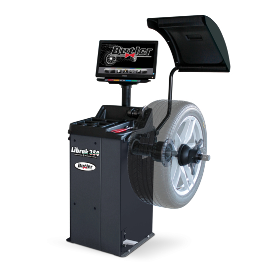
1296-M024-01 INSTRUCTION, USE AND Page 5 of 61 MAINTENANCE MANUAL LIBRAK350 - LIBRAK350PRO GENERAL DESCRIPTION Fig. 1 1 – Weight holding bridge 10 – Pressure ring 2 – Monitor 11 – Grippers for weights 3 – Distance-diameter caliper 12 – Carriages counterweight 4 –... -
Page 6: Symbols Used In The Manual
1296-M024-01 INSTRUCTION, USE AND MAINTENANCE MANUAL Page 6 of 61 LIBRAK350 - LIBRAK350PRO SYMBOLS USED IN THE MANUAL Symbols Description Symbols Description Read instruction manual. Danger! Be particularly careful. Move with fork lift truck or pal- Wear work gloves. let truck. -
Page 7: Information Plate Location Drawing
1296-M024-01 INSTRUCTION, USE AND Page 7 of 61 MAINTENANCE MANUAL LIBRAK350 - LIBRAK350PRO INFORMATION PLATE LOCATION DRAWING Code numbers of plates 99990114 Arrow plate 99990758 Electric shock danger plate 999910050 Protection device use plate 999912940 Lifting plate 999914160 230V 50/60 Hz 1 Ph voltage plate... -
Page 8: General Introduction
1296-M024-01 INSTRUCTION, USE AND MAINTENANCE MANUAL Page 8 of 61 LIBRAK350 - LIBRAK350PRO INTENDED USE SOME OF THE PICTURES AND/ OR DISPLAY SCREEN PAGES The machine described in this manual , and their PRESENT IN THIS MANUAL HAVE different versions, is a wheel balancing machine... -
Page 9: Safety Devices
1296-M024-01 INSTRUCTION, USE AND Page 9 of 61 MAINTENANCE MANUAL LIBRAK350 - LIBRAK350PRO SAFETY DEVICES GENERAL SAFETY RULES DAILY CHECK THE INTEGRITY AND THE FUNCTIONALITY OF THE SAFETY AND PROTECTION DEVICES ON THE MACHINE. • Any tampering with or modification to the machine not previously authorized by the manufacturer ex- • Control logic disposition... -
Page 10: Packing And Mobilization For Transport
1296-M024-01 INSTRUCTION, USE AND MAINTENANCE MANUAL Page 10 of 61 LIBRAK350 - LIBRAK350PRO PACKING AND MOBILIZATION FOR OPERATORS MUST WEAR SUIT- TRANSPORT ABLE WORK CLOTHES, PROTEC- TIVE GLASSES AND GLOVES, AGAINST THE DANGER FROM THE SPRAYING OF DANGEROUS DUST, AND POSSIBLY LOWER... -
Page 11: Unpacking
1296-M024-01 INSTRUCTION, USE AND Page 11 of 61 MAINTENANCE MANUAL LIBRAK350 - LIBRAK350PRO UNPACKING MOBILIZATION DURING UNPACKING, ALWAYS WEAR GLOVES TO PREVENT ANY INJURY CAUSED BY CONTACT THE LIFTING EQUIPMENT MUST WITHSTAND WITH PACKAGING MATERIAL A MINIMUM RATED LOAD EQUAL TO THE (NAILS, ETC.). -
Page 12: Working Environment Conditions
1296-M024-01 INSTRUCTION, USE AND MAINTENANCE MANUAL Page 12 of 61 LIBRAK350 - LIBRAK350PRO WORKING ENVIRONMENT CONDI- The base floor must be able to support the loads trans- mitted during operation. TIONS This surface must have a capacity load of at least 500 The machine must be operated under proper condi- Kg\m²... -
Page 13: Machine Assembly
1296-M024-01 INSTRUCTION, USE AND Page 13 of 61 MAINTENANCE MANUAL LIBRAK350 - LIBRAK350PRO MACHINE ASSEMBLY • To fasten the product to the ground, use anchoring plugs (Fig._4 ref. 1) with a threaded shank M8 (UNC EACH MECHANICAL INTERVEN- 5/16) suitable for the floor on which the tyre changer... -
Page 14: Assembly Procedures
1296-M024-01 INSTRUCTION, USE AND MAINTENANCE MANUAL Page 14 of 61 LIBRAK350 - LIBRAK350PRO Assembly procedures 9.2.2 Protection guard assembly (standard on some models) 9.2.1 Fitting the shaft on the flange 1. Screw the 3 bolts (Fig. 6 ref. 1) and the washers (Fig. -
Page 15: Monitor Fitting
1296-M024-01 INSTRUCTION, USE AND Page 15 of 61 MAINTENANCE MANUAL LIBRAK350 - LIBRAK350PRO 9.2.3 Monitor fitting 3. Secure the monitor (Fig. 8 ref. 1) to the support (Fig. 8 ref. 2) with the bolts (Fig. 8 ref. 3) and the 1. -
Page 16: Fitting Of External Data Gauge (Standard On Some Models)
1296-M024-01 INSTRUCTION, USE AND MAINTENANCE MANUAL Page 16 of 61 LIBRAK350 - LIBRAK350PRO 9.2.4 Fitting of external data gauge (stand- 5. Also make sure the gauge tip (Fig. 11 ref. 1) is positioned APPROXIMATELY at the centre of the ard on some models) chuck. -
Page 17: Electrical Connections
1296-M024-01 INSTRUCTION, USE AND Page 17 of 61 MAINTENANCE MANUAL LIBRAK350 - LIBRAK350PRO 10.0 ELECTRICAL CONNECTIONS 10.1 Electrical checks EVEN THE TINIEST PROCEDURE B E F O R E S TA R T I N G U P T H E... -
Page 18: Fitting The Wheel On The Shaft
1296-M024-01 INSTRUCTION, USE AND MAINTENANCE MANUAL Page 18 of 61 LIBRAK350 - LIBRAK350PRO 11.0 FITTING THE WHEEL ON THE Fig. 15 SHAFT To achieve perfect balancing, the wheel must be care- fully and properly fitted on the shaft. Imperfect centring will inevitably cause unbalances. -
Page 19: Control Panel
1296-M024-01 INSTRUCTION, USE AND Page 19 of 61 MAINTENANCE MANUAL LIBRAK350 - LIBRAK350PRO 13.0 WHEEL BALANCING THE PRESSURE RING (FIG. 17 REF . 1) MUST BE MOUNTED WITH THE TEETH OR DISCHARGE SIDE 13.1 Switching the machine on and off TOWARDS THE RING-NUT (FIG. -
Page 20: Balancing Programs Setting
INSTRUCTION, USE AND MAINTENANCE MANUAL Page 20 of 61 LIBRAK350 - LIBRAK350PRO At the bottom of the main screen page and of each W H E N T H E E Q U I P M E N T I S... -
Page 21: Programs Rapid Setting And Measurements Through Distance- Diameter Caliper Arm
1296-M024-01 INSTRUCTION, USE AND Page 21 of 61 MAINTENANCE MANUAL LIBRAK350 - LIBRAK350PRO 13.2.1 Programs rapid setting and meas- - bring into contact the weights fitting gripper with the inner part of the rim (2 contact points) (see Fig. urements through distance-diameter Fig. - Page 22 1296-M024-01 INSTRUCTION, USE AND MAINTENANCE MANUAL Page 22 of 61 LIBRAK350 - LIBRAK350PRO • Measuring procedure of electronic RUN-OUT with - The following screen page will appear on the monitor: the distance-diameter caliper arm. Fig. 26 The electronic RUN-OUT measuring device is useful to check if the rim has some imperfections.
-
Page 23: Programs Setting Through "Measurements Acquisition
1296-M024-01 INSTRUCTION, USE AND Page 23 of 61 MAINTENANCE MANUAL LIBRAK350 - LIBRAK350PRO 13.2.2 Programs setting through “Measure- Fig. 28 ments acquisition” screen page From the “Home” page, press the (Fig. 19 ref. 1) button to display "Measurements acquisition" screen page below: 1 –... -
Page 24: Indicative Display Of Points Where To Detect Measures/To Fit Weight
1296-M024-01 INSTRUCTION, USE AND MAINTENANCE MANUAL Page 24 of 61 LIBRAK350 - LIBRAK350PRO 13.3 Indicative display of points where to detect measures/to fit weight - Press the button to display the following pro- grams selection screen page: IT IS VERY IMPORTANT TO RE-... -
Page 25: Weights Positioning
1296-M024-01 INSTRUCTION, USE AND Page 25 of 61 MAINTENANCE MANUAL LIBRAK350 - LIBRAK350PRO 13.3.1 Weights positioning 13.4 Displaying the active/modifiable field The monitor displays when it is absolutely necessary During the various phases of measures detection, the that the weight is applied at "12 o'clock" position. Pay active field turns yellow. -
Page 26: Wheel Balancing Screen Page Description
1296-M024-01 INSTRUCTION, USE AND MAINTENANCE MANUAL Page 26 of 61 LIBRAK350 - LIBRAK350PRO 13.5 Wheel balancing screen page descrip- NORMALLY DURING THE DETEC- tion TION OF MEASUREMENTS, THE 1ST ACTIVE FIELD WILL BE THE After executing the spin of the wheel, the monitor dis-... - Page 27 1296-M024-01 INSTRUCTION, USE AND Page 27 of 61 MAINTENANCE MANUAL LIBRAK350 - LIBRAK350PRO The following screen will appear on the moni- tor: SPLIT MATCHING program program Press again the button to display the ECO-WEIGHT SPOKES approximated weight to be fitted to the wheel,...
-
Page 28: Balancing Mode
1296-M024-01 INSTRUCTION, USE AND MAINTENANCE MANUAL Page 28 of 61 LIBRAK350 - LIBRAK350PRO 13.5.1 Balancing mode The machine has the ability to perform the wheel bal- ancing (weights fitting) in 4 different ways: - using the distance-diameter caliper arm with weights fitting grippers;... - Page 29 1296-M024-01 INSTRUCTION, USE AND Page 29 of 61 MAINTENANCE MANUAL LIBRAK350 - LIBRAK350PRO 4. Bring the distance-diameter caliper arm in resting • Weights fitting at “6 o'clock” (without the use of position, after having led it towards the chuck to laser emitter).
-
Page 30: Use Of Machines With Disabled Automatic Data Gauge
1296-M024-01 INSTRUCTION, USE AND MAINTENANCE MANUAL Page 30 of 61 LIBRAK350 - LIBRAK350PRO 13.6 Use of machines with disabled auto- VALUE IN VALUE IN VALUE matic data gauge MILLIMETRES INCHES DETECTED ON TO BE ENTERED TO BE ENTERED THE GRADUATED... -
Page 31: Manual Setting Of Wheel Dimensions
1296-M024-01 INSTRUCTION, USE AND Page 31 of 61 MAINTENANCE MANUAL LIBRAK350 - LIBRAK350PRO 13.6.1 Manual setting of wheel dimensions 13.7 Standard balancing programs In case the operator wants to edit and/or manually 13.7.1 Static enter the wheel dimensions, proceed as follows:... -
Page 32: Static-2
1296-M024-01 INSTRUCTION, USE AND MAINTENANCE MANUAL Page 32 of 61 LIBRAK350 - LIBRAK350PRO 13.7.3 Static-2 13.7.5 ALU-S STATIC 2 function is a procedure that offsets wheel ALU-S program permits balancing wheels by two fit- vibrations using a single adhesive weight on a single ting adhesive weights on the outer and inner sides of plane positioned exactly at “12 o'clock”. -
Page 33: Alu-S2
1296-M024-01 INSTRUCTION, USE AND Page 33 of 61 MAINTENANCE MANUAL LIBRAK350 - LIBRAK350PRO 13.7.7 ALU-S2 13.7.9 ALU-2 ALU-S2 function permits balancing wheels with light ALU-2 function balances wheels with light alloy rims alloy rims by fitting two adhesive weights: one on the... -
Page 34: Optional Balancing Programs
1296-M024-01 INSTRUCTION, USE AND MAINTENANCE MANUAL Page 34 of 61 LIBRAK350 - LIBRAK350PRO 13.7.11 ALU-4 13.8 Optional balancing programs ALU-4 function is a procedure that uses mixed weights 13.8.1 ECO-WEIGHT mode to offset wheel unbalance: weight with clip on inner side of wheel, adhesive weight on outer side. - Page 35 1296-M024-01 INSTRUCTION, USE AND Page 35 of 61 MAINTENANCE MANUAL LIBRAK350 - LIBRAK350PRO Press the brake pedal and fit the adhesive weight inside pliers as shown in Fig. 34. Fig. 34 Fit the adhesive weight in the pliers of the gauge rod...
-
Page 36: Split Mode
1296-M024-01 INSTRUCTION, USE AND MAINTENANCE MANUAL Page 36 of 61 LIBRAK350 - LIBRAK350PRO 13.8.2 SPLIT mode IMMEDIATELY AFTER HAVING SELECTED THE ECO -WEIGHT Split procedure proves useful when the dynamic unbal- PROCEDURE, YOU CAN KNOW ance of a wheel is fairly high and the weight to be fitted IN ADVANCE THE TWO DYNAMIC is not available, for instance a 100 g weight. - Page 37 1296-M024-01 INSTRUCTION, USE AND Page 37 of 61 MAINTENANCE MANUAL LIBRAK350 - LIBRAK350PRO TWO SMALLER WEIGHTS (55g) (1.94 oz) USING SPLIT PROCEDURE Press button to select the outer weight to edit. Press buttons to increase or decrease the total weight to be fitted.
-
Page 38: Weights Hidden Behind Spokes
1296-M024-01 INSTRUCTION, USE AND MAINTENANCE MANUAL Page 38 of 61 LIBRAK350 - LIBRAK350PRO Fit the clip weight of the chosen value at “12 o'clock” on 13.8.3 Weights hidden behind spokes mode Adhesive correction weight positioning may not look the outside of the wheel. Press again button attractive on some types of rims. - Page 39 1296-M024-01 INSTRUCTION, USE AND Page 39 of 61 MAINTENANCE MANUAL LIBRAK350 - LIBRAK350PRO Bring any spoke upwards at "12 o'clock" position and Perform another test spin. The “weights hidden behind spokes” procedure is completed. press the button to confirm and continue.
-
Page 40: Matching Mode
1296-M024-01 INSTRUCTION, USE AND MAINTENANCE MANUAL Page 40 of 61 LIBRAK350 - LIBRAK350PRO 13.8.4 Matching mode On the monitor the next screen page will be displayed: The Matching procedure offsets strong unbalance, reducing the weight quantity to be fitted on the wheel to achieve balancing. - Page 41 1296-M024-01 INSTRUCTION, USE AND Page 41 of 61 MAINTENANCE MANUAL LIBRAK350 - LIBRAK350PRO STEP 2. Remove the wheel from the wheel balancer. Fig. 36 Remove the tyre and turn it on the rim through 180°. Fit the wheel back on the wheel balancer, positioning...
-
Page 42: Special Balancing Programs
1296-M024-01 INSTRUCTION, USE AND MAINTENANCE MANUAL Page 42 of 61 LIBRAK350 - LIBRAK350PRO 13.9 Special balancing programs - Press the button to bring the wheel into posi- 13.9.1 Pax tion. PAX mode is a special procedure specially devised to balance wheels using the “PAX System ®”. 2 adhesive weights on different planes are used on rim inner side. -
Page 43: Recalculation Function
1296-M024-01 INSTRUCTION, USE AND Page 43 of 61 MAINTENANCE MANUAL LIBRAK350 - LIBRAK350PRO 13.10 Recalculation function 13.11 Wheel balancing in Motorcycle mode (with distance caliper extension Kit) After making a spin, the wheel automatically stops, indicating the weight/s to be fitted and its/their position. -
Page 44: User Menu (Options And Calibration)
1296-M024-01 INSTRUCTION, USE AND MAINTENANCE MANUAL Page 44 of 61 LIBRAK350 - LIBRAK350PRO 14.0 USER MENU (OPTIONS AND CALI- 14.1 Options menu BRATION) Press button to display the monitor screen to enable/disable the options as shown below: From the main page “Home” press the button to move to the next screen page and the button to access the user menu. - Page 45 1296-M024-01 INSTRUCTION, USE AND Page 45 of 61 MAINTENANCE MANUAL LIBRAK350 - LIBRAK350PRO List of available options Enable/disable the lock function for THE ICONS OF THE AVAILABLE caliper arm in position. OPTIONS WILL TURN BLUE WHEN THEY ARE SELECTED. It allows you to change the unit of...
-
Page 46: Lower Weight Limit
1296-M024-01 INSTRUCTION, USE AND MAINTENANCE MANUAL Page 46 of 61 LIBRAK350 - LIBRAK350PRO 14.1.1 Lower weight limit Correction weight below a certain limit is normally Enable/disable user function. shown equal to zero. This limit can be set from 10 g to 1 g (from 0.5 oz to 0.05 oz). -
Page 47: Setting Adhesive Weight Dimensions And Static Threshold Percentage
1296-M024-01 INSTRUCTION, USE AND Page 47 of 61 MAINTENANCE MANUAL LIBRAK350 - LIBRAK350PRO 14.1.2 Setting adhesive weight dimensions 14.1.3 User management and static threshold percentage The "User Management" function is disabled on ma- chine delivery. To enable it, proceed as described in To ensure the balancing machine precisely calculates Para 14.1. -
Page 48: Enabling Of Electronic Run-Out Measuring Device
1296-M024-01 INSTRUCTION, USE AND MAINTENANCE MANUAL Page 48 of 61 LIBRAK350 - LIBRAK350PRO 14.2 Enabling of electronic Run-out measur- ing device Press button , shown on the monitor (Fig. 41 ref. 2) or select the field (Fig. 42 ref. 1) and subse- From the main page “Home”... -
Page 49: Machine Calibrations
1296-M024-01 INSTRUCTION, USE AND Page 49 of 61 MAINTENANCE MANUAL LIBRAK350 - LIBRAK350PRO 14.3 Machine calibrations Press button to display the monitor screen to enable/disable the options as shown below: Press the button (Fig. 39 ref. 2) to display the following screen page on monitor: Fig. -
Page 50: Chuck "0" (Zero) Calibration
1296-M024-01 INSTRUCTION, USE AND MAINTENANCE MANUAL Page 50 of 61 LIBRAK350 - LIBRAK350PRO 14.3.1 Chuck “0” (zero) calibration 14.3.2 Weight measurement sensors calibra- tion Press the button (Fig. 44 ref. 1) to display the following screen page on the monitor:... - Page 51 1296-M024-01 INSTRUCTION, USE AND Page 51 of 61 MAINTENANCE MANUAL LIBRAK350 - LIBRAK350PRO - Remove the weight from 100 g (3.52 oz) from the outside of the wheel and apply it on the inner side at "12 o'clock". AT THIS POINT TAKE THE WEIGHT...
-
Page 52: Gauges Calibration
1296-M024-01 INSTRUCTION, USE AND MAINTENANCE MANUAL Page 52 of 61 LIBRAK350 - LIBRAK350PRO 14.3.3 Gauges calibration Place the gauge (Fig. 45 ref. 1) on the chuck flange (Fig. 45 ref. 2). Fig. 45 Press the button (Fig. 44 ref. 3) to display the... - Page 53 1296-M024-01 INSTRUCTION, USE AND Page 53 of 61 MAINTENANCE MANUAL LIBRAK350 - LIBRAK350PRO - Place the gauge as shown in the following figure: - Press push button On the monitor the next screen page will be dis- played: Measure the exact diameter of a rim (see Fig. 47) and place it on the screen on the monitor by pressing the buttons.
- Page 54 1296-M024-01 INSTRUCTION, USE AND MAINTENANCE MANUAL Page 54 of 61 LIBRAK350 - LIBRAK350PRO - Turn the gauge ferrule (Fig. 48 ref. 1) on the inner Calibration of external data gauge (standard on edge of the wheel upwards (see Fig._48). some models) Fig.
- Page 55 1296-M024-01 INSTRUCTION, USE AND Page 55 of 61 MAINTENANCE MANUAL LIBRAK350 - LIBRAK350PRO Press button Press button On the monitor the next screen page will be displayed: At the end of the operation, the following screen will appear on the monitor: Move the tip of the width measuring device (Fig.
-
Page 56: Error Signals
INSTRUCTION, USE AND MAINTENANCE MANUAL Page 56 of 61 LIBRAK350 - LIBRAK350PRO 15.0 ERROR SIGNALS During wheel balancer operation, if wrong commands are given by the operator or device faults occur, an error code may appear on the monitor screen. -
Page 57: Routine Maintenance
1296-M024-01 INSTRUCTION, USE AND Page 57 of 61 MAINTENANCE MANUAL LIBRAK350 - LIBRAK350PRO 16.0 ROUTINE MAINTENANCE To guarantee the efficiency and correct functioning of the machine, it is essential to carry out daily or weekly cleaning and weekly routine maintenance, as BEFORE CARRYING OUT ANY ROU- described below. -
Page 58: Technical Data
1296-M024-01 INSTRUCTION, USE AND MAINTENANCE MANUAL Page 58 of 61 LIBRAK350 - LIBRAK350PRO 17.0 TECHNICAL DATA 17.1 Technical electrical data Max. absorbed voltage (W) Voltage (V) Power supply Phases Frequency (Hz) 50/60 Typical current draw (A) Rotation speed (rev/min) < 100 17.2 Technical mechanical data... -
Page 59: Dimensions
1296-M024-01 INSTRUCTION, USE AND Page 59 of 61 MAINTENANCE MANUAL LIBRAK350 - LIBRAK350PRO 17.3 Dimensions Fig. 51 * Standard on some models... -
Page 60: Storing
1296-M024-01 INSTRUCTION, USE AND MAINTENANCE MANUAL Page 60 of 61 LIBRAK350 - LIBRAK350PRO 18.0 STORING 20.0 REGISTRATION PLATE DATA If storing for long periods disconnect the main power supply and take measures to protect the machine from dust build-up. Lubricate parts that could be damaged from drying out. - Page 61 22 – Width potentiometer extension cable 11 – Piezo with front cable 23 – Potentiometer with shielded cable 12 – Piezo with cable 24 – Cable from transformer to power supply LIBRAK350 - LIBRAK350PRO 1296-M024-01 WIRING CONNECTION DIAGRAM Page 61 of 61 Drawing N°A - Rev.
- Page 62 The technical documentation file is constituted by Butler S.p.A.s.u. Vorgesetzte Rechtsperson für die Erstellung des technischen Lastenheftes ist Butler S.p.A.s.u. La société Butler S.p.A.s.u. est l'organisme délégué à la presentation de la documentation technique. Butler S.p.A.s.u. es encargata a la constitución del archivo técnico.
Need help?
Do you have a question about the LIBRAK350 and is the answer not in the manual?
Questions and answers