Table of Contents
Advertisement
Quick Links
www.ti.com
User's Guide
IWR6843L EVM
Chethan Kumar Y.B.
The IWR6843LEVM from Texas Instruments is an easy-to-use low cost FR4-based evaluation board for the
XWR6843 mmWave sensing device, with direct connectivity to the MMWAVEICBOOST and DCA1000EVM
development kits. This EVM contains everything required to start developing software for on-chip C67x DSP
core and low power Arm
®
Started........................................................................................................................................................................2
Features......................................................................................................................................................................2
Contents........................................................................................................................................................................2
2 Hardware.................................................................................................................................................................................
Diagram....................................................................................................................................................................5
3.1 PCB Storage and Handling Recommendations.................................................................................................................
Antenna..........................................................................................................................................................6
4.1 Transmitter and Receiver Virtual Array..............................................................................................................................
Details.....................................................................................................................................................................8
Settings...................................................................................................................................................................8
5.2
LEDs...................................................................................................................................................................................9
5.3
Connectors.........................................................................................................................................................................9
5.4 USB Connector..................................................................................................................................................................
Connector..................................................................................................................................................10
5.6 MMWAVEICBOOST HD Connector.................................................................................................................................
5.7 CANFD Connector...........................................................................................................................................................
Connections...............................................................................................................................................................11
5.9 EEPROM..........................................................................................................................................................................
5.10 Default I2C Address.......................................................................................................................................................
Mode.................................................................................................................................................................11
5.12 Flashing the Board.........................................................................................................................................................
Mode......................................................................................................................................................13
5.15 Raw ADC Data Capture Using MMWAVEICBOOST and DCA1000 EVMs...................................................................
5.16 Muxing Scheme.............................................................................................................................................................
7 TI E2E Community................................................................................................................................................................
8 References............................................................................................................................................................................
Trademarks
Arm
®
and Cortex
®
are registered trademarks of Arm Limited (or its subsidiaries) in the US and/or elsewhere.
All trademarks are the property of their respective owners.
SWRU585 - NOVEMBER 2021
Submit Document Feedback
Cortex
®
-R4F controllers
Table of Contents
Demo................................................................................................................................................2
Recommendations...................................................................................................................6
Applications..............................................................................................................................6
Mode.............................................................................................................................................14
Code............................................................................................................15
Copyright © 2021 Texas Instruments Incorporated
ABSTRACT
Table of Contents
3
6
7
9
10
10
11
11
13
15
15
15
15
IWR6843L EVM
1
Advertisement
Table of Contents

Subscribe to Our Youtube Channel
Related Manuals for Texas Instruments IWR6843L EVM


Summary of Contents for Texas Instruments IWR6843L EVM
-
Page 1: Table Of Contents
Chethan Kumar Y.B. ABSTRACT The IWR6843LEVM from Texas Instruments is an easy-to-use low cost FR4-based evaluation board for the XWR6843 mmWave sensing device, with direct connectivity to the MMWAVEICBOOST and DCA1000EVM development kits. This EVM contains everything required to start developing software for on-chip C67x DSP core and low power Arm ®... -
Page 2: Getting Started
IWR6843 radar sensor. For details on getting started with these demos, see www.ti.com/tool/mmwave-sdk. CAUTION • Caution Hot Surface • Contact May Cause Burn • Do Not Touch IWR6843L EVM SWRU585 – NOVEMBER 2021 Submit Document Feedback Copyright © 2021 Texas Instruments Incorporated... -
Page 3: Hardware
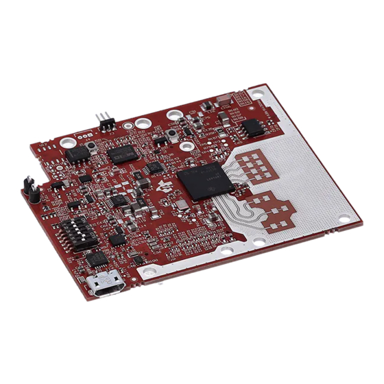
The IWR6843 operates at a 4-GHz bandwidth from 60 to 64 GHz. The IWR6843LEVM has an antenna gain of ~5-6 dBi across different antenna pairs. Figure 2-1. IWR6843LEVM Top View Figure 2-2. IWR6843LEVM Bottom View SWRU585 – NOVEMBER 2021 IWR6843L EVM Submit Document Feedback Copyright © 2021 Texas Instruments Incorporated... - Page 4 Hardware www.ti.com Figure 2-3. Salient features of EVM (top side) Figure 2-4. Salient features of EVM (bottom side) IWR6843L EVM SWRU585 – NOVEMBER 2021 Submit Document Feedback Copyright © 2021 Texas Instruments Incorporated...
-
Page 5: Block Diagram
LVDS DP [7:0] OPTIONAL VBGAP GPIO [2:0] 1.2 V 1.8 V 1.0 V DCA1000 60 PIN CONNECTOR 60 PIN CONNECTOR Figure 2-5. Functional Block Diagram SWRU585 – NOVEMBER 2021 IWR6843L EVM Submit Document Feedback Copyright © 2021 Texas Instruments Incorporated... -
Page 6: Pcb Storage And Handling Recommendations
The IWR6843LEVM includes four receivers and three transmitters FR4 based antennas on the PCB. Figure 4-1 shows the Antenna configuration. Figure 4-1. TX and Rx Antennas of the EVM IWR6843L EVM SWRU585 – NOVEMBER 2021 Submit Document Feedback Copyright © 2021 Texas Instruments Incorporated... -
Page 7: Transmitter And Receiver Virtual Array
Note Wavelength (Lambda) is computed based on a 62 GHz frequency. Antenna placements are done according to this frequency. Figure 4-3. Azimuth Antenna Radiation Patterns SWRU585 – NOVEMBER 2021 IWR6843L EVM Submit Document Feedback Copyright © 2021 Texas Instruments Incorporated... -
Page 8: Hardware Details
60 pin connector, J1, J6 S1.5 Muxes USER UART to 60 pin header J1 Muxes USER UART to USB connector J5 S1.6 Reset switch GPIO1 toggle switch IWR6843L EVM SWRU585 – NOVEMBER 2021 Submit Document Feedback Copyright © 2021 Texas Instruments Incorporated... -
Page 9: Leds
UART • MSS logger UART (can be used to get MSS code logs on the PC) Figure 5-2. USB Connector (J5) SWRU585 – NOVEMBER 2021 IWR6843L EVM Submit Document Feedback Copyright © 2021 Texas Instruments Incorporated... -
Page 10: Dca1000 Hd Connector
The CAN connector provides access to the two CAN_FD interfaces (CAN_L and CAN_H signals) from the onboard CAND-FD transceivers. These signals can be directly wired to the CAN bus. Figure 5-5. CANFD Connector IWR6843L EVM SWRU585 – NOVEMBER 2021 Submit Document Feedback Copyright © 2021 Texas Instruments Incorporated... -
Page 11: I2C Connections
Figure 5-6. Figure 5-6. Virtual COM Port The SICP2105 drivers must be installed to access the UART port. Download and install the drivers here. SWRU585 – NOVEMBER 2021 IWR6843L EVM Submit Document Feedback Copyright © 2021 Texas Instruments Incorporated... - Page 12 The S1 switch setting for functional and flashing mode is shown in Table 5-5. Table 5-5. S1 Swtch Setting for Functional and Flashing Mode S1.1 S1.2 S1.3 S1.4 S1.5 S1.6 Flashing Functional IWR6843L EVM SWRU585 – NOVEMBER 2021 Submit Document Feedback Copyright © 2021 Texas Instruments Incorporated...
-
Page 13: Flashing The Board
S1 switch settings for this mode is shown in Table 5-6. Table 5-6. S1 Configuration for DCA1000EVM Mode S1.1 S1.2 S1.3 S1.4 S1.5 S1.6 DCA1000EMV mode SWRU585 – NOVEMBER 2021 IWR6843L EVM Submit Document Feedback Copyright © 2021 Texas Instruments Incorporated... -
Page 14: Mmwaveicboost Mode
SOP mode is set by the MMWAVEICBOOST. More on the mmWAVEICBOOST, setup and features it provides can be found in the MMWAVEICBOOST section MMWAVEICBOOST EVM userguide. Figure 5-10. MMWAVEICBOOST Mode IWR6843L EVM SWRU585 – NOVEMBER 2021 Submit Document Feedback Copyright © 2021 Texas Instruments Incorporated... -
Page 15: Raw Adc Data Capture Using Mmwaveicboost And Dca1000 Evms
Hardware Setup for IWR6843ISK and IWR6843ISK-ODS | TI.com Video • Hardware Setup for MMWAVEICBOOST and antenna module | TI.com Video • mmwave-sdk • USB to UART Drivers for the CP2105 SWRU585 – NOVEMBER 2021 IWR6843L EVM Submit Document Feedback Copyright © 2021 Texas Instruments Incorporated... - Page 16 TI products. TI’s provision of these resources does not expand or otherwise alter TI’s applicable warranties or warranty disclaimers for TI products. TI objects to and rejects any additional or different terms you may have proposed. IMPORTANT NOTICE Mailing Address: Texas Instruments, Post Office Box 655303, Dallas, Texas 75265 Copyright © 2022, Texas Instruments Incorporated...
Need help?
Do you have a question about the IWR6843L EVM and is the answer not in the manual?
Questions and answers