Table of Contents
Advertisement
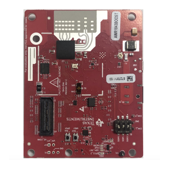
xWR1843 Evaluation Module (xWR1843BOOST)
The xWR1843 BoosterPack™ from Texas Instruments™ is an easy-to-use evaluation board for the
xWR1843 mmWave sensing device, with direct connectivity to the microcontroller (MCU) LaunchPad™
Development Kit. The BoosterPack contains everything required to start developing software for on-chip
C67x DSP core and low-power Arm
debugging as well as onboard buttons and LEDs for quick integration of a simple user interface.
1
1.1
1.2
1.3
......................................................................................................................
2
2.1
2.2
2.3
2.4
2.5
2.6
2.7
2.8
3
3.1
3.2
4
5
6
7
..................................................................................................................
8
Trademarks
BoosterPack, Texas Instruments, LaunchPad, Code Composer Studio are trademarks of Texas
Instruments.
Arm is a registered trademark of Arm Limited.
Windows is a registered trademark of Microsoft Corporation.
All other trademarks are the property of their respective owners.
SPRUIM4B - December 2018 - Revised May 2020
Submit Documentation Feedback
Single-Chip mmWave Sensing Solution
R4F controllers, including onboard emulation for programming and
®
...............................................................................................................
..........................................................................................................
.......................................................................................................
..........................................................................................................
.......................................................................................................
.................................................................................................
..........................................................................................................
......................................................................................................
.............................................................................................................
...................................................................................
.........................................................................................
...........................................................................................................
..................................................................................................
.............................................................................................
............................................................................................................
xWR1843 Evaluation Module (xWR1843BOOST) Single-Chip mmWave
Copyright © 2018-2020, Texas Instruments Incorporated
SPRUIM4B - December 2018 - Revised May 2020
Contents
.................................................................
...........................................................
........................................................................
User's Guide
2
2
2
2
3
5
5
6
9
9
............................
10
11
13
16
16
16
18
18
19
19
19
1
Sensing Solution
Advertisement
Table of Contents


Need help?
Do you have a question about the WR1843 Series and is the answer not in the manual?
Questions and answers