Subscribe to Our Youtube Channel
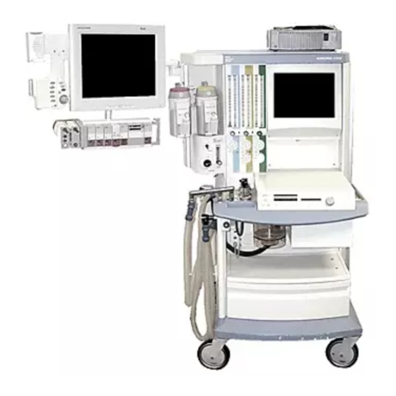
Summary of Contents for Dräger Medical NM6000
- Page 1 RETURN TO SERVICE PROCEDURE TABLE OF CONTENTS RETURN TO CD-ROM TABLE OF CONTENTS Field Service Procedure Part Number: SP00244 Rev: B Date: 28 March 2003 © 2003 Draeger Medical, Inc. NM6000 Auxiliary Video Installation...
- Page 2 RETURN TO SERVICE PROCEDURE TABLE OF CONTENTS RETURN TO CD-ROM TABLE OF CONTENTS...
- Page 3 RETURN TO SERVICE PROCEDURE TABLE OF CONTENTS RETURN TO CD-ROM TABLE OF CONTENTS NM6000 Auxiliary Video Installation Installation Procedure 1.0 Installing the Video Splitter: NOTE: Machine must be equipped with a flat panel display (not CRT type). If applicable, refer to Flat Panel Upgrade kit, P/N 4116805.
- Page 4 RETURN TO SERVICE PROCEDURE TABLE OF CONTENTS RETURN TO CD-ROM TABLE OF CONTENTS Installation Procedure (continued) VIDEO CABLE (NEW) SP24401 EXISTING VIDEO CABLE FLAT PANEL POWER PCB (EXISTING) HD15 F-F ADAPTER AUX POWER VIDEO PCB CABLE SPLITTER EXISTING 6-32 KEP POWER NUT (4X) CABLE...
- Page 5 NOTE: The next step is for NM6400 machines ONLY. Skip step and discard label (P/N 4118305) when installing Auxiliary Video in other NM6000 Series machines. 1.20 Apply label (P/N 4118305) on the rear cover as shown in Figure 2. Apply label so that the indicated area of silkscreen is covered.
- Page 6 RETURN TO SERVICE PROCEDURE TABLE OF CONTENTS RETURN TO CD-ROM TABLE OF CONTENTS Installation Procedure (continued) NEW REAR COVER NEW REAR COVER 5 3/16" IF NARKOMED 6400, APPLY LABEL 4118305 OVER THIS AREA OF SILKSCREEN VIDEO 1 VIDEO 2 VIDEO 3 4 7/16"...
- Page 7 RETURN TO SERVICE PROCEDURE TABLE OF CONTENTS RETURN TO CD-ROM TABLE OF CONTENTS Installation Procedure (continued) 2.0 Installing the Battery Shield and Drawer Ground: Pull the drawer all the way out and remove it from its tracks by pulling up on both black retaining clips.
- Page 8 RETURN TO SERVICE PROCEDURE TABLE OF CONTENTS RETURN TO CD-ROM TABLE OF CONTENTS Installation Procedure (continued) Place the ground clamp (4117792) on the rear edge of the drawer - oriented as shown in Figure 4, and mark its location. Remove the paint from the drawer where the clamp set screws will contact bare metal when the clamp is installed.
- Page 9 NOTE: Proceed to Section 3 or Section 4 if you are installing a display unit at this time. This completes the NM6000 auxiliary video installation. 2.12 Restore power to the machine and perform the PHASE adjustment on the flat panel display as given in Section 5.7A of the Narkomed 6000 Technical Service manual.
- Page 10 RETURN TO SERVICE PROCEDURE TABLE OF CONTENTS RETURN TO CD-ROM TABLE OF CONTENTS Installation Procedure (continued) SP24406 10-32 KEP NUT GROUND STRAP ASSEMBLY FIGURE 6. Ground Strap Installation...
- Page 11 Figure 7. Connect the other end of the cord to a hospital AC wall outlet. CAUTION: Do Not plug the other end of the power cord into the convenience outlet on the machine. This completes the NM6000 auxiliary video installation with machine-mounted remote display option.
- Page 12 RETURN TO SERVICE PROCEDURE TABLE OF CONTENTS RETURN TO CD-ROM TABLE OF CONTENTS Installation Procedure (continued) 3.14 Restore power to the machine and perform the PHASE adjustment on the flat panel display as given in Section 5.7A of the Narkomed 6000 Technical Service manual. 3.15 Reinstall the table lamp panel at the front of the machine.
- Page 13 RETURN TO SERVICE PROCEDURE TABLE OF CONTENTS RETURN TO CD-ROM TABLE OF CONTENTS Installation Procedure (continued) DISPLAY UNIT SP24407 GCX COUNTER TOP ARM DISPLAY POWER GCX TOP SHELF CHANNEL CORD & BASE PLATE 12 IN. GCX RAIL VIDEO CABLE TRANSFORMER MOUNTING PLATE AUXILIARY OUTLET...
- Page 14 Do Not plug the other end of the power cord into the convenience outlet on the machine. This completes the NM6000 auxiliary video installation with wall-mounted remote display option. Restore power to the machine and perform the PHASE adjustment on the flat panel display as given in Section 5.7A of the Narkomed 6000 Technical Service manual.
- Page 15 RETURN TO SERVICE PROCEDURE TABLE OF CONTENTS RETURN TO CD-ROM TABLE OF CONTENTS Installation Procedure (continued) 4.11 Verify the machine’s self-diagnostics, flat panel display, remote display, auxiliary lamp and strip chart recorder (if fitted) are working properly. 4.12 Perform electrical safety and battery tests; refer to Section 6 in the Narkomed 6000 Technical Service Manual.
- Page 16 RETURN TO SERVICE PROCEDURE TABLE OF CONTENTS RETURN TO CD-ROM TABLE OF CONTENTS Installation Procedure (continued) DISPLAY UNIT SP24408 GCX PIVOT ARM 19 IN. GCX RAIL VIDEO CABLE 10-32 KEP NUT (4X) TRANSFORMER DISPLAY POWER CORD MOUNTING PLATE ISOLATION TRANSFORMER POWER CORD DUST...
- Page 17 RETURN TO SERVICE PROCEDURE TABLE OF CONTENTS RETURN TO CD-ROM TABLE OF CONTENTS...
- Page 18 RETURN TO SERVICE PROCEDURE TABLE OF CONTENTS RETURN TO CD-ROM TABLE OF CONTENTS DrägerService is a division of Draeger Medical, Inc. 3122 Commerce Drive Telford, PA 18969 Tel: (215) 721-5402 (800) 543-5047 Fax: (215) 721-5784 Web: www.draegermedical.com Printed in the U.S.A.


Need help?
Do you have a question about the NM6000 and is the answer not in the manual?
Questions and answers