
Related Manuals for Lowrance X52


Summary of Contents for Lowrance X52
- Page 1 Pub. 988-0151-211 www.lowrance.com X52 and X59DF Fish-Finding & Depth-Sounding Sonars Installation and Operation Instructions...
- Page 2 Lowrance. Any unauthorized commercial distribution of this manual is strictly prohibited. Lowrance Electronics may find it necessary to change or end our policies, regulations, and special offers at any time. We reserve the right to do so without notice. All features and specifications subject to change without notice.
-
Page 3: Table Of Contents
Table of Contents Introduction ... i Capabilities and Specifications: X52 and X59DF... 1 Installation & Accessories... 3 Preparations... 3 Transducer Installation... 3 Recommended Tools and supplies... 4 Selecting a Transducer Location ... 4 How low should you go? ... 5 Shoot-Thru-Hull vs. - Page 4 Backlight Level ... 46 Calibrate Speed... 46 Chart Speed... 46 Grayline ... 47 Contrast... 48 Depth Cursor... 49 Depth Range - Automatic ... 50 Depth Range - Manual ... 50 Depth Range - Upper and Lower Limits ... 51 To change the upper and lower limits:...
-
Page 5: Introduction
( However, if you want to fine-tune your unit, press the X52 and X59DF have several powerful features you can control by scrolling through easy-to-use menus with the arrow and menu keys. - Page 6 Sonar comes packed with the X59DF. It has 35°/12° cone angles. Single frequency models for X52 with a 20° cone angle are sold separately. Both models offer a wide fish detection area of up to 60º with high sensitivity settings.
-
Page 7: Installation & Accessories
Installation & Accessories Preparations You can install the sonar system in some other order if you prefer, but we recommend this installation sequence: CAUTION: You should read over this entire installation section before drilling any holes in your vehicle or vessel! 1. -
Page 8: Recommended Tools And Supplies
Recommended Tools and supplies If you prefer the option of routing the cable through the transom, you will need a 5/8" drill bit. (If you intend to install an additional speed or temp sensor and route its cable through the same hole in the transom, you will need a 1"... -
Page 9: How Low Should You Go
3. The transducer should be installed with its face pointing straight down, if possible. For shoot-thru applications: Many popular fishing boat hulls have a flat keel pad that offers a good mounting surface. On vee hulls, try to place the transducer where the deadrise is 10° or less. Left, vee pad hull;... -
Page 10: Shoot-Thru-Hull Vs. Transom Mounting
Transom Hull bottom Align transducer centerline with hull bottom. A dual frequency transducer is shown at left and a single frequency transducer at right. However, there are times when you may need to adjust the transducer slightly higher or lower. (The slots in the mounting brackets allow you to loosen the screws and slide the transducer up or down.) If you frequently lose bottom signal lock while running at high speed, the transducer may be coming out of the water as you cross waves or... -
Page 11: Transom Transducer Assembly And Mounting
Second, the transducer angle cannot be adjusted for the best fish arches on your sonar display. (This is not an issue for flasher-style sonars.) Lack of angle adjustment can be particularly troublesome on hulls that sit with the bow high when at rest or at slow trolling speeds. Third, a transducer CAN NOT shoot through wood and metal hulls. - Page 12 with the alignment mark molded into the bracket. Place the ratchets onto the transducer with the letter "A" aligned with the 12 o'clock position on the transducer stem. These positions set the transducer's coarse angle adjustment for a 14° transom. Most outboard and stern- drive transoms have a 14°...
- Page 13 holes in the bracket with the letter "B" aligned with the dot stamped in the bracket. Reassemble the transducer and bracket and place them against the transom. Again, check to see if you can move the transducer so it's parallel with the ground. If you can, then go to step 3A. If it doesn't, repeat step 2A, but use a different alignment letter until you can place the transducer on the transom correctly.
- Page 14 Bolt Flat washer Assemble transducer and bracket. 3. Assembling the transducer. A. One-piece bracket: Once you determine the correct position for the ratchets, assemble the transducer as shown in the following figure. Don't tighten the lock nut at this time. Rubber washers Assemble transducer and bracket.
- Page 15 Drill the holes. For the one-piece bracket, use the #29 bit (for the #10 screws). For the two-piece bracket, use the #20 bit (for the #12 screws). Transom Transom Position transducer mount on transom and mark mounting holes. Side view shown at left and seen from above at right. 5.
- Page 16 bracket's mounting screws, sealing them with the sealant/adhesive compound. Adjust the transducer so that it's parallel to the ground and tighten the nut until it touches the outer washer, then add 1/4 turn. Don't over tighten the lock nut! If you do, the transducer won't "kick-up" if it strikes an object in the water.
-
Page 17: Trolling Motor Bracket Installation
Manual locking collar connector requires a 1" hole. Caution: If you drill a hole in the transom for the cable, make sure it is located above the waterline. After installation, be sure to seal the hole with the same marine grade above- or below-waterline sealant/adhesive used for the mounting screws. -
Page 18: Transducer Orientation And Fish Arches
Transducer mounted on trolling motor, side view. Transducer Orientation and Fish Arches If you do not get good fish arches on your display, it could be because the transducer is not parallel with the ground when the boat is at rest in the water or at slow trolling speeds. -
Page 19: Shoot-Thru-Hull Preparation
the arch is printed, then the nose of the transducer is angled too far down and needs to be raised. NOTE: Periodically wash the transducer's face with soap and water to remove any oil film. Oil and dirt on the face will reduce the sensitivity or may even prevent operation. -
Page 20: Testing Determines Best Location
Testing Determines Best Location Ideally, the shoot-thru transducer should be installed as close to the transom as possible, close to the centerline. This will give you the best performance during high speed maneuvers. Transducer location Transducer location (high speed) (trolling speed) Shoot-thru-hull transducer locations for high speed or trolling speed operation. -
Page 21: Shoot-Thru-Hull Installation
figure on the following page.) Notice how the signal strength decreases. The second bottom signal will probably disappear and the bottom signal intensity will likely decrease. 3. Now move the transducer around to find the best location with the strongest possible bottom signal. If you find a spot with an acceptable bottom signal, mark the location and move on to step 4. - Page 22 Sand this surface (unit's face) Orient the Skimmer with the nose facing the bow of the boat. 2. The epoxy consists of the epoxy itself and a hardener. Remove the two compounds from the package and place them on the paper plate. Thoroughly stir the two compounds together until the mixture has a uniform color and consistency.
-
Page 23: Speed/Temperature Sensors
Speed/Temperature Sensors Optional Temperature Sensor All the units in this series can display water temperature from a single analog sensor. Your unit comes packed with a transducer with a temp sensor built into it. If you wish to purchase an optional additional sensor for your unit, refer to the accessory ordering information inside the back cover of this manual. -
Page 24: Power Connections
Good location Stern view showing good location for mounting sensor on transom. Transom Speed sensor mounting configuration: side view (left) and rear view (right.) If the base of the transom has a radius, fill the gap between the transom and the sensor with the sealant. This will help ensure a smooth water flow. -
Page 25: Powering A Nmea 2000 Buss (Nmea 2000 Power Cable)
2000 Power". The thicker three-wire cable (red, black and white) is the Power Supply for your unit (and optional external speaker connection for some units); it has no label on the cable. To unit Blue connector The Power/Data cable for this unit. Depending on your configuration, you may not use all of these wires. - Page 26 with electrical interference. Therefore, it's safer to go ahead and attach the power cable directly to the battery. CAUTION: When using the unit in a saltwater environment, we strongly recommend that you shut off the power supply to the power cable when the unit is not in use.
- Page 27 Blue connector To power a NMEA 2000 buss, also connect NMEA 2000 Power cable to the boat's battery. NMEA 0183 Data Cable Power connections for the units in this series. NOTES: If you're powering a NMEA 2000 buss, you will attach both the NMEA 2000 Power cable and the unit's Power Supply cable to the boat's battery.
-
Page 28: Nmea 2000 Cable Connections
NMEA 2000 buss installed. Over the next few years, however, NMEA 2000 will become much more common. To help you get the most out of this technology, your Lowrance unit is designed to work with a NMEA 2000 network as soon as it becomes available. -
Page 29: Mounting The Unit: Bracket, In-Dash Or Portable
Sonar unit, rear view Power/Data socket (blue socket nut) All blue connectors NMEA 0183 data cable (unused) NMEA 2000 power cable Main power supply cable Mounting the Unit: Bracket, In-Dash or Portable You can install the unit on the top of a dash with the supplied gimbal bracket. - Page 30 If you use the supplied bracket, you may be interested in the optional R-A-M bracket mounting system. This converts the unit's gimbal bracket to a swivel mount, which can be used on the dash or overhead mounting positions. Optional R-A-M mounting system. Bracket Installation Mount the unit in any convenient location, provided there is clearance behind the unit when it's tilted for the best viewing angle.
- Page 31 If you choose to fill in the hole, be sure to position the cables against the rear edge of the hole as you apply the fill material. [5.20] Front view (left) and side view (right) showing dimensions of X52 and X59DF sonar unit when mounted on gimbal bracket. [5.35] 61.3 [2.42]...
- Page 32 Portable Installation Like many Lowrance products, this sonar unit is capable of portable operation by using an optional portable power pack. The power pack and an optional portable transducer expand the uses for your sonar unit.
-
Page 33: Other Accessories
it to the dock, on a float tube, on an ice fishing trip or use it as a second sonar in a friend's boat. Look inside the back cover of this manual for accessory ordering information. Other Accessories Two switch boxes are available for this unit. The SB-9BL transducer switch box switches two transducers to one sonar unit. - Page 34 Notes...
-
Page 35: Basic Sonar Operation
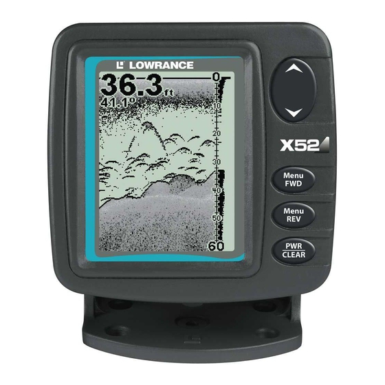
The unit sounds a tone when you press any key. This tells you the unit has accepted a command. Numbers in the photo correspond to key explanations below: Lowrance X59DF Sonar, front view, showing screen and keyboard. 1. MENU/PWR (menu and power) This key appears in the manual text simply as turn the unit on and off. -
Page 36: Memory
3. EXIT Press this key to clear menus from the screen and return to the Sonar Chart display. You will also use to cancel alarms, and to clear any EXIT information windows that may appear on the screen. 4. UP and DOWN ARROWS These keys appear in the manual text as ↓... - Page 37 Main Menu. Main Menu Commands There are four "basic" Main Menu commands that you'll really want to read more about. They are: • Screen commands ( ): change the ONTRAST ACKLIGHT EVEL appearance of the display screen. Use these commands to adjust how the screen looks under various lighting conditions.
-
Page 38: Sonar Menu
• Set Keel Offset command: calibrates the unit to show depth under the keel or actual depth from the surface. • Calibrate Water Speed command: adjusts how a speed sensor measures water speed. • Reset Water Distance command: resets water distance log to zero. •... - Page 39 Section, but Sensitivity and Auto Sensitivity are important basic functions that are discussed both here and in the Advanced Section. The other Sonar Menu commands include: • Grayline command: separates fish and structure near the bottom from the actual bottom, and defines bottom composition/hardness. •...
- Page 40 Digital data overlay (depth & temperature) Fish arches around school of bait fish Structure Sonar Page, showing full sonar chart mode. Sonar chart display options (from left) full sonar chart and split zoom. Surface signal Bottom signal Surface clutter Depth scale In FasTrack, fish arches show as horizontal bars.
- Page 41 Sonar chart display options (from left) digital data and flasher. You can customize how the Sonar Page pictures and other data are displayed in many ways. We'll discuss all of those features and options in the Advanced Section, but to show you how easy the sonar unit is to operate, the following page contains a simplified, 10-step quick reference that will cover most fish finding situations.
-
Page 42: Basic Sonar Quick Reference
Basic Sonar Quick Reference 1. Mount the transducer and unit. Connect the unit to electric power and the transducer. 2. Launch your boat. 3. To turn on the unit, press and release 4. Head for your fishing grounds. Your unit automatically displays digital depth and surface water temperature in the corner of the screen. -
Page 43: Sonar Operations
Sonar Operations As you can see from the quick reference on the previous page, basic operation is pretty easy, right out of the box. If you are a sonar novice, try operating the unit with the factory defaults until you get a feel for how it's working. As you're learning the basics, there is one setting you might want to tinker with from time to time —... - Page 44 You can change the sensitivity level whether you are in Auto Sensitivity mode or Manual Sensitivity mode. The adjustment method works the same in both modes, but it gives you slightly different results. Adjusting sensitivity in Auto Sensitivity Mode is similar to manually adjusting a car's speed with the accelerator pedal while cruise control is on.
-
Page 45: Fish Symbols Vs. Full Sonar Chart
San Francisco Bay saw clouds of clutter in the water but no fish arches. When a down rigger was pulled up, it brought up several small jellyfish. The fishermen switched their Lowrance sonar to Fish I.D., which screened out the schools of jellyfish and clearly showed the game fish there as fish symbols. -
Page 46: Other Free Training Aids
Visit our web site, . Be sure to check out the free WWW.LOWRANCE.COM Sonar Tutorial, which includes animated illustrations and more pictures of actual sonar returns, all described in detail. There's even a "printer friendly"... -
Page 47: Advanced Sonar Options & Other Features
Advanced Sonar Options & Other Features Material in this section is arranged in alphabetical order. ASP (Advanced Signal Processing) The ASP feature is a noise rejection system built into the sonar unit that constantly evaluates the effects of boat speed, water conditions and interference. -
Page 48: Alarms
Alarms This unit has two different types of sonar alarms. The first is a Fish Alarm. It sounds when the Fish I.D. feature determines that an echo is a fish. The other alarm is the Depth Alarm, which has both a Shallow and a Deep setting. -
Page 49: Fish Alarm
To switch to a different depth setting, open the Sonar Alarms menu and repeat the instructions in step 3 above. To adjust and turn on the deep alarm: 1. Press MENU MENU 2. Press ↓ to 3. Press ↑ or ↓ until the depth is correct, then press 4. -
Page 50: Backlight Level
Backlight Level The unit defaults to the maximum backlight level. To adjust the display's backlight level: Press |↓ to . The slider MENU MENU ACKLIGHT EVEL ACKLIGHT EVEL bar appears. Press ↑ or ↓ to move the bar. At The lower end of the scale backlighting is turned off;... -
Page 51: Grayline
However, you might consider experimenting with chart speed when you are stationary or drifting very slowly. You may sometimes achieve better images as you slow down the chart speed to match how fast you are moving across the bottom. If you are at anchor, ice fishing or fishing from a dock, experiment with a chart speed around 50 percent. -
Page 52: Contrast
If you have two signals of equal size, one with gray and the other without, then the target with gray is the stronger signal. This helps distinguish weeds from trees on the bottom, or fish from structure. Grayline is adjustable. The factory default for this unit is 69 percent. Since Grayline shows the difference between strong and weak signals, adjusting the sensitivity may also require a different Grayline level. -
Page 53: Depth Cursor
The Contrast control bar. Depth Cursor The depth cursor consists of a horizontal line with a digital depth box on the right side. The numbers inside the box show the depth of the cursor. Cursor line Depth box Sonar chart with the depth cursor active. The line indicates the large fish is 40.52 feet deep. -
Page 54: Depth Range - Automatic
Depth Range - Automatic When turned on for the first time, the bottom signal is automatically placed in the lower half of the screen. This is called Auto Ranging and is part of the automatic function. However, depending upon the bottom depth and the current range, you can change the range to a different depth. -
Page 55: Depth Range - Upper And Lower Limits
Depth Range - Upper and Lower Limits Virtually any segment of the water column can be displayed by using the upper and lower limit feature. This lets you pick the shallow and deep depth range limits that are shown on the screen, provided there is at least 5 feet between the upper and lower limit you select. -
Page 56: To Turn Off Upper And Lower Limits
3. To set the lower limit, press ↓ to the depth is correct, then press To turn off upper and lower limits: 1. From the Sonar Page, press FasTrack This feature automatically converts all echoes to short horizontal lines on the display's far right side. The graph on the rest of the screen continues to operate normally. -
Page 57: Fishtrack
extending outwards from a group of limbs is the hardest object for the Fish I.D. feature to distinguish from fish. You may see fish symbols on the screen when actually, there are no fish. The reverse is also true. Does that mean Fish I.D. is broken? No — the feature is simply interpreting sonar returns in a specific way to help take some of the work out of reading the screen. -
Page 58: Overlay Data
targets. This feature is available only when the Fish I.D. feature is on. The default setting for FishTrack is off. To turn on FishTrack: (Note: These instructions will turn on FishTrack and Fish I.D. at the same time.) 1. From the Sonar Page, press 2. - Page 59 The Overlay Data selection menu. When selected, a check mark appears beside the data type. (If you wish, you may now use ↓ or ↑ to select other Data Types for display.) Data list showing "Water Speed" selected to display on Sonar Page. 3.
-
Page 60: Ping Speed & Hyperscroll
3. To return to the previous page, press To change displayed data font size: 1. Press |↓ to MENU 2. Press ↓ or ↑ to select Data Type, then press (displayed in the bottom of the Overlay Data Shown window) cycles through available sizes. -
Page 61: To Change Ping Speed
However, when you are running at high speeds, or just want the fastest possible screen update, you may want to use the HyperScroll feature. When you change the Ping Speed to any setting greater than 50 percent, the unit automatically enters HyperScroll mode. These faster ping rates allow you to maintain a high-detail picture on the screen, and the screen refresh rate and chart scroll speed can keep pace with the boat as it moves quickly over the bottom terrain. -
Page 62: Pop-Up Help
2. The Ping Speed Control Bar appears. Press ↓ to decrease ping speed to 50 percent. When it's set at the desired level, press When you boost ping speed and switch into HyperScroll, the width of the FasTrack bar graph display doubles in width at the right side of the screen. -
Page 63: Reset Water Distance
3. All the menus are cleared and all options are returned to the factory settings. Main Menu with Reset Options command selected. Reset Water Distance The sonar chart's Digital Data display option includes a window that shows distance traveled, called Water Distance ("W Distance"). This information is calculated from an optional water speed sensor. - Page 64 Automatic Sensitivity The default sensitivity mode is automatic. The unit bases the sensitivity level on water depth and conditions. When the unit is in the automatic mode, sensitivity is automatically adjusted to keep a solid bottom signal displayed, plus a little more power. This gives it the capability to show fish and other detail.
-
Page 65: To Turn Auto Sensitivity Back On
To adjust sensitivity in manual mode: 1. First, turn off Auto Sensitivity: from the Sonar Page, press ENSITIVITY 2. Press ↑ to ENSITIVITY Press ↓ or ↑ to pick a different sensitivity setting. When it's set at the desired level, press To turn Auto Sensitivity back on: From the Sonar Page, press NOTE:... -
Page 66: Set Language
Software Version Information From time to time, Lowrance updates the operating system software in some of its products. These software upgrades are usually offered to customers as free downloads from our web site, www.lowrance.com. -
Page 67: Sonar Chart Mode
The Main Menu with Software Information command selected. 1. Press MENU MENU 2. Read the information displayed on the screen. To return to the last page displayed, press EXIT|EXIT. Sonar Chart Mode Grayscale is the default setting for the sonar chart, but we offer other variations to suit your viewing preferences. -
Page 68: Split Zoom Sonar Chart
targets. The line at the top of the screen represents the surface. The bottom depth and surface temperature (if equipped with a temperature sensor or a transducer with a temp sensor built in) show at the top left corner of the screen. The FasTrack™... -
Page 69: Digital Data/Chart
Split Zoom Sonar Chart. Image at left shows the left window zoomed to 2X. The right image shows the left window zoomed to 4X. The depth overlay data is set to the default large text size; the water temperature is set to the medium text size. Digital Data/Chart This mode shows six large digital boxes or windows containing: Water Depth;... -
Page 70: Flasher
Flasher The Flasher page represents a flasher style sonar. A circular dial shows all returning echoes at a high screen refresh rate. It uses the Grayline feature to show weaker targets as lighter shades. The bottom depth is also shown as a black bar across the outer circle. Bottom signal Sonar Simulator This unit has a built-in simulator that lets you run it as if you were on... -
Page 71: Surface Clarity
stops the chart from scrolling. Sonar restarts automatically each time you turn on your unit. Press |↓ to MENU EXIT HART To turn on sonar and start the chart scrolling again, repeat the above step. Sonar Menu with Stop Chart command selected. The box is unchecked, indicating that the chart is scrolling across the screen. -
Page 72: Units Of Measure
Sonar Features menu with Surface Clarity selected. ↓ or ↑ to select clarity level| Press Surface clutter In the illustration at left, Surface Clarity is turned off. The right view shows Surface Clarity set at High. Units of Measure This menu sets the speed and distance (statute or nautical miles, meters), depth (feet, fathoms, or meters) and temperature (degrees Fahrenheit or Celsius). -
Page 73: Upper And Lower Limits
The Units of Measure Menu. To set Units of Measure: Press ↓ to the desired units, then press ENT. After all the options are set as desired, press to return to the EXIT|EXIT page display. Upper and Lower Limits See the entry in this section for Depth Range - Upper and Lower Limits Volume This command adjusts the speaker volume, which controls the sound levels for keystrokes and alarms. -
Page 74: Zoom Pan
To switch to zoom: 1. Press |↓ to MENU 2. The Zoom Level menu appears. Press ↓ or ↑ to select the desired zoom level, then press 3. To select a different zoom or turn zoom off, repeat steps 1 and 2. To turn on the Zoom Bar: 1. -
Page 75: Troubleshooting
Troubleshooting If your unit is not working, or if you need technical help, please use the following troubleshooting section before contacting the factory customer service department. It may save you the trouble of returning your unit for repair. For contact information, refer to the last page, just inside the back cover of this manual. - Page 76 specially formulated so that it will cure properly for shoot-through applications. 2. Electrical noise from the boat's motor can interfere with the sonar. This causes the sonar to automatically increase its Discrimination or noise rejection feature. This can cause the unit to eliminate weaker signals such as fish or even structure from the display.
- Page 77 4. The boat must be moving at a slow trolling speed to see fish arches. If the boat is motionless, fish stay in the cone, showing on the screen as straight horizontal lines. Noise A major cause of sonar problems is electrical noise. This usually appears on the sonar's display as random patterns of dots or lines.
- Page 78 that has a smooth flow of water at all boat speeds. Read your transducer owner's manual for the best mounting position.
-
Page 79: Index
Accessories, 1, 3, 25, 26, 29 Alarms, 33, 44, 45; Depth Alarms, 44; Fish Alarm, 44, Antenna, 73 ASP (Advanced Signal Processing), 16, 43 Backlights / Lighting, 1, 33, 46, Batteries, 3, 21, 22, 23, 32, 71, 72, 73 Calibrate Speed, 46 Chart Speed, 35, 46, 47 Communications Ports, 20, 21, 23, 24... - Page 80 Reset Water Distance, 34, 59 Route, 3, 4, 5, 11, 12, 13, 18, 20, 71, 73 Sensitivity, 16, 35, 38, 39, 40, 41, 57, 58, 59, 60, 61, 70, 73 Simulator, 1, 34, 66 Software Version Information, Sonar Chart Color Mode, 63 Sonar Chart Display Options, 31, 35, 63, 64, 65 Sonar Menu, 31, 32, 34, 58, 67,...
- Page 81 LOWRANCE ELECTRONICS FULL ONE-YEAR WARRANTY "We," "our," or "us" refers to LOWRANCE ELECTRONICS, INC., the manufacturer of this product. "You" or "your" refers to the first person who purchases this product as a consumer item for personal, family or household use.
-
Page 82: How To Obtain Service
…in the USA: We back your investment in quality products with quick, expert service and genuine Lowrance parts. If you're in the United States and you have technical, return or repair questions, please contact the Factory Customer Service Department. Before any product can be returned, you must call customer service to determine if a return is necessary. -
Page 83: Accessory Ordering Information For All Countries
1) Your local marine dealer. Most quality dealers that handle marine electronic equipment should be able to assist you with these items. To locate a Lowrance dealer near you, visit our web site and look for the Dealer Locator (www.lowrance.com/support/dealerlocator). Or, you can consult your telephone directory for listings. -
Page 84: Visit Our Web Site
Visit our web site: Lowrance Pub. 988-0151-211 Copyright © 2004 All Rights Reserved Printed in USA 111904 Lowrance Electronics, Inc.
Need help?
Do you have a question about the X52 and is the answer not in the manual?
Questions and answers