
Related Manuals for Lowrance X96


Summary of Contents for Lowrance X96
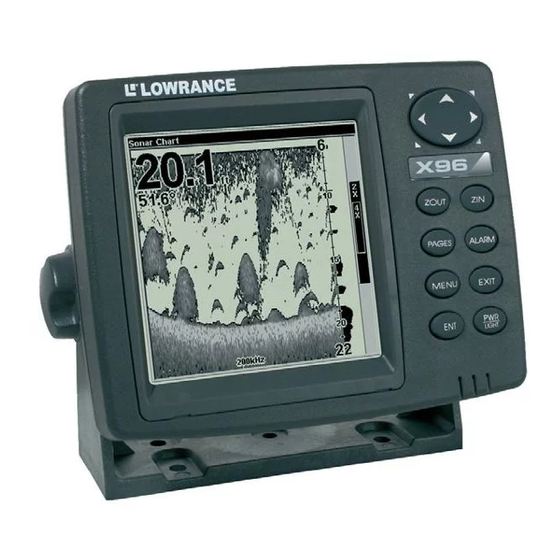
- Page 1 Pub. 988-0151-401 www.lowrance.com X96 & X96TX Fish-finding & Depth Sounding Sonar Installation and Operation Instructions...
- Page 2 We reserve the right to do so without notice. All features and specifications subject to change without notice. All screens in this manual are simulated. On the cover: X96 shown. For free owner's manuals and other information, visit our web site: www.lowrance.com...
-
Page 3: Table Of Contents
Section 1: Read Me First!... 1 Capabilities and Specifications: X96 & X96TX ... 2 How Sonar Works ... 3 How to use this manual: typographical conventions ... 3 Arrow Keys ... 4 Keyboard ... 4 Menu Commands ... 4 Instructions = Menu Sequences ... 4 Section 2: Installation &... - Page 4 To adjust and turn on the shallow alarm: ... 40 To adjust and turn on the deep alarm: ... 41 Zone Alarm ... 41 To adjust and turn on the zone alarm:... 41 Fish Alarm... 42 To turn on the fish alarm:... 42 Brightness ...
- Page 5 Software Version Information... 62 Sonar Chart Mode... 63 To change the chart mode scheme: ... 63 Sonar Chart Display Options ... 63 Full Sonar Chart ... 64 Digital Data/Chart ... 65 Customizing the Digital Data Screen ... 65 Sonar Simulator... 66 Stop Chart ...
- Page 6 A CAREFUL NAVIGATOR NEVER RELIES ON ONLY ONE METHOD TO OBTAIN POSITION INFORMATION. When showing navigation data to a position (waypoint), a GPS unit will show the shortest, most direct path to the waypoint. It provides navigation data to the waypoint regardless of obstructions.
-
Page 7: Section 1: Read Me First
Section 1: Read Me First! How this manual can get you out on the water, fast! Welcome to the exciting world of digital sonar! We know you're anxious to begin finding fish, but we have a favor to ask. Before you grab your unit and begin installing it, please give us a moment to explain how our manual can help you get the best performance from your compact, wide-screen, fish finder. -
Page 8: Capabilities And Specifications: X96 & X96Tx
3 for important information on how sonar works. Capabilities and Specifications: X96 & X96TX Display:... 5.0" (12.7 cm) diagonal high contrast Film Resolution:... 320 pixel x 320 pixel resolution; 102,400 total Backlighting: ……………Incandescent backlit screen with multiple... -
Page 9: How Sonar Works
Audible alarms: ... Deep/shallow/fish/zone. Automatic ranging:... Yes, with instant screen updates. Zoom bottom track: ... Yes. Split-screen zoom:... Yes. Surface water temp: ... Yes. Speed/distance log: ... Optional (requires optional speed sensor). NOTICE! The storage temperature range for your unit is from -4 degrees to +167 degrees Fahrenheit (-20 degrees to +75 degrees Celsius). -
Page 10: Arrow Keys
The following paragraphs explain how to interpret the text formatting for those commands and other instructions: Arrow Keys The arrow keys control a horizontal line depth cursor on the sonar screen. The arrow keys also help you move around the menus so you can execute different commands. -
Page 11: Section 2: Installation & Accessories
Installation & Accessories Preparations You can install the sonar system in some other order if you prefer, but we recommend this installation sequence: Caution: You should read over this entire installation section before drilling any holes in your vessel! 1. Determine the approximate location for the sonar unit, so you can plan how and where to route the cables for the transducer and power. -
Page 12: Recommended Tools And Supplies
Remember, the transducer installation is the most critical part of a sonar installation. Recommended Tools and supplies If you prefer the option of routing the cable through the transom, you will need a 5/8" drill bit. A transom mount requires use of a high quality, marine grade above- or below-waterline caulking compound. -
Page 13: How Low Should You Go
Electrical noise from engine wiring, bilge pumps and aerators can be displayed on the sonar's screen. Use caution when routing the transducer cable around these wires. CAUTION: Clamp the transducer cable to transom near the transducer. This will help prevent the transducer from entering the boat if it is knocked off at high speed. -
Page 14: Shoot-Thru-Hull Vs. Transom Mounting
If you cruise or fish around lots of structure and cover, your transducer may be frequently kicking up from object strikes. If you want, you may move the transducer a little higher for more protection. There are two extremes you should avoid. Never let the edge of the mounting bracket extend below the bottom of the hull. - Page 15 Align plastic ratchets in bracket. B. Two-piece bracket: Locate the four plastic ratchets in the transducer's hardware package. Press two ratchets into the sides of the plastic bracket and two on either side of the transducer as shown in the following illustrations.
- Page 16 Trans ducer Transducer bracket Ratchet Ratchet Add ratchets to bracket and transducer. 2. Aligning the transducer on the transom. A. One-piece bracket: Slide the transducer between the two ratchets. Temporarily slide the bolt though the transducer assembly and hold it against the transom. Looking at the transducer from the side, check to see if it will adjust so that its face is parallel to the ground.
- Page 17 B. Two-piece bracket: Assemble the transducer and bracket as shown in the following figure. Temporarily slide the bolt though the transducer assembly but do not tighten the nut at this time. Hold the assembled transducer and bracket against the transom. Looking at the transducer from the side, check to see if it will adjust so its face is parallel to the ground.
- Page 18 B. Two-piece bracket: Once you determine the correct position for the ratchets, assemble the transducer as shown in the figure in step 2B. Don't tighten the lock nut at this time. 4. Drilling mounting holes. Hold the transducer and bracket assembly against the transom. The transducer should be roughly parallel to the ground.
- Page 19 Both bracket types: Attach the transducer to the transom. Slide the transducer up or down until it's aligned properly with the bottom of the hull as shown in the preceding and following figures. Tighten the bracket's mounting screws, sealing them with the caulking compound. Adjust the transducer so that it's parallel to the ground and tighten the nut until it touches the outer washer, then add 1/4 turn.
- Page 20 7. Make a test run to determine the results. If the bottom is lost at high speed, or if noise appears on the display, try sliding the transducer bracket down. This puts the transducer deeper into the water, hopefully below the turbulence causing the noise. Don't allow the transducer bracket to go below the bottom of the hull! TROLLING MOTOR BRACKET INSTALLATION 1.
- Page 21 TRANSDUCER ORIENTATION AND FISH ARCHES If you do not get good fish arches on your display, there is a good possibility the transducer is not parallel with the ground when the boat is at rest in the water or at slow trolling speeds. Transducer aimed too far back Full fish arch...
- Page 22 A successful transducer installation can be made on hulls with flotation materials (such as plywood, balsa wood or foam) between layers of fiberglass if the material is removed from the selected area. Fill with epoxy Flotation material Epoxy to hull first Epoxy the transducer to a solid portion of the hull.
-
Page 23: Shoot-Thru-Hull Installation
If not, then mark the location that gave you the best sonar returns and read through the instructions on the following pages for shoot-thru-hull mounting. Transducer location (high speed) Shoot-thru-hull transducer locations for high speed or trolling speed operation. Shoot-thru-hull Installation 1. -
Page 24: Speed/Temperature Sensors
Place the transducer into the epoxy, twisting and turning it to force any air bubbles out from under the transducer face. The face of the transducer should be parallel with the hull, with a minimum amount of epoxy between the hull and transducer. After the epoxy dries, route the cable to the sonar unit. - Page 25 Power/trans- ducer cable. Sonar unit with secondary temperature sensor. Primary temp sensor Power/trans- ducer cable. Sonar unit with external speed sensor or combo speed/temp sensor. The primary temperature sensor is built into the transducer. Sonar unit rear view Temp sensor built into transducer is built into the transducer.
-
Page 26: Optional Speed Sensor Installation
Optional Speed Sensor Installation If you wish to purchase an optional speed sensor for your unit, refer to the accessory ordering information inside the back cover of this manual. The following instructions describe how to install the speed sensor. Recommended tools for this job include: drill, 5/8" drill bit, 1/8" drill bit for pilot holes, screwdriver. -
Page 27: Power Connections
If the base of the transom has a radius, fill the gap between the transom and the sensor with the caulking compound. This will help ensure a smooth water flow. Route the sensor's cable through or over the transom to the sonar unit. If you need to drill a hole in the transom to pass the connector through, the required hole size is 5/8". -
Page 28: Mounting The Unit: Bracket, In-Dash Or Portable
To unit Power connections for the sonar unit. CAUTION: Do not use this product without a 3-amp fuse wired into the power cable! Failure to use a 3-amp fuse will void your warranty. This unit has reverse polarity protection. No damage will occur if the power wires are reversed. -
Page 29: Bracket Installation
bracket to a swivel mount, which can be used on the dash or overhead mounting positions. Installation instructions are supplied with the R-A-M mounting kits. Optional R-A-M mounting system. Bracket Installation Mount the unit in any convenient location, provided there is clearance behind the unit when it's tilted for the best viewing angle. - Page 30 Drill a 1-inch (25.4 mm) hole in the dash for the power and transducer cables. The best location for this hole is immediately under the gimbal bracket location. This way, the bracket can be installed so that it covers the hole, holds the cables in position and results in a neat installation. Some customers, however, prefer to mount the bracket to the side of the cable hole —...
-
Page 31: In-Dash Installation
In-Dash Installation You can mount the unit in the dash with an optional FM-5 In-Dash Adapter Kit. The kit includes mounting hardware, a template for cutting the hole and an instruction sheet, part 988-0147-43. In-dash mounting template for the sonar unit, showing dimensions. - Page 32 Install batteries in power pack battery adapter.
-
Page 33: Section 3: Basic Sonar Operation
Section 3: Basic Sonar Operation This section addresses the unit's most basic sonar operations. The instructions presented in Sec. 3 follow a chronological order. Sec. 4, Sonar Options & Other Features, will discuss other more advanced functions and utilities. Material in Sec. 4 is arranged in alphabetical order. -
Page 34: Power/Lights On And Off
4. ARROW KEYS – Used to navigate through the menus, make menu selections, move the sonar chart cursor and enter data. 5. ENT – Allows you to accept values or execute menu commands. 6. EXIT – Lets you return to the previous screen, clear data or erase a menu. - Page 35 Main Menu. The Main Menu commands and their functions are: Screen: changes the contrast or brightness of the display screen. Sounds: enables or disables the sounds for key strokes and alarms and sets the alarm style. Sonar Alarms: turns alarms on or off and changes alarm thresholds. Units of Measure: changes units of measure used for depth, speed, distance and temperature.
-
Page 36: Sonar Pages
Sonar page options (left). Sonar page menu (right). Sonar Pages Sonar pages display a cross-section view of the water column beneath the boat. The chart moves across the screen, displaying sonar signal echoes that represent fish, structure and the bottom. The sonar page menu has its own menu, which is used for some advanced functions and for setting various options. - Page 37 Full Sonar Chart (left). Split Zoom Sonar Chart (right). Digital Data Sonar Chart (left). FlashGraf Chart (right).
- Page 38 Digital data overlay (depth & temperature) Fish arches Structure Bottom signal Sonar Page, showing full sonar chart mode. You can customize how the Sonar Page displays its pictures and other data in many ways. Your unit also includes several features and options that can help you better interpret the underwater scene.
-
Page 39: Basic Sonar Quick Reference
Basic Sonar Quick Reference 1. Mount the transducer and unit. Connect the unit to electric power and the transducer. 2. Launch your boat. 3. To turn on the unit, press and release 4. Head for your fishing grounds. Your unit automatically displays digital depth and surface water temperature in the corner of the screen. -
Page 40: Sonar Operations
Sonar Operations As you can see from the quick reference on the previous page, basic operation is pretty easy, right out of the box. If you are a sonar novice, try operating the unit with the factory defaults until you get a feel for how it's working. As you're learning the basics, there is one setting you might want to tinker with from time to time —... - Page 41 You can change the sensitivity level whether you are in Auto Sensitivity mode or Manual Sensitivity mode. The adjustment method works the same in both modes, but it gives you slightly different results. Adjusting sensitivity in Auto Sensitivity Mode is similar to manually adjusting a car's speed with the accelerator pedal while cruise control is on.
-
Page 42: Fish Symbols Vs. Full Sonar Chart
Sonar Menu with Sensitivity command selected (left). The Sensitivity Control Bar (right). NOTE: If you want to change the sensitivity in Manual Mode, first turn off Auto Sensitivity. From the Sonar Page, press |↑ to ENSITIVITY sensitivity setting. When it's set at the desired level, press Important Tip: While you are experimenting with the many options in the X-96, it's possible to scramble the settings so the sonar picture disappears... -
Page 43: Other Free Training Aids
Fish I.D. is most handy when you're in another part of the boat or performing some task that prevents you from watching the sonar screen. Then you can turn on Fish I.D. and the audible fish alarm. When that lunker swims under your boat, you'll hear it! Fish I.D. - Page 44 Notes...
-
Page 45: Section 4: Options & Features
Section 4: Options & Features ASP (Advanced Signal Processing) The ASP feature is a noise rejection system built into the sonar unit that constantly evaluates the effects of boat speed, water conditions and interference. This automatic feature gives you the best display possible under most conditions. -
Page 46: Alarms
Alarms This unit has three types of sonar alarms. The first is the Fish Alarm. It sounds when the Fish I.D. feature determines an echo is a fish. Another alarm is the Zone Alarm, which consists of a bar on the side of the screen. -
Page 47: To Adjust And Turn On The Deep Alarm
4. Press ← to HALLOW 5. To turn off the alarm, press To switch to a different depth setting, open the Sonar Alarms menu and repeat the instructions in step 3 above. To adjust and turn on the deep alarm: 1. -
Page 48: Fish Alarm
Notice the size of the black alarm bar on the right side of the screen changes as you manipulate the ↑ ↓ keys. 4. To set the lower boundary for the Zone Alarm, use ← or→ to select , then press ↑ or ↓ to move the bottom of the bar to the desired OWER depth. -
Page 49: Calibrate Speed
Calibrate Speed The speed sensor can be calibrated to compensate for inaccuracies. Before you change the setting, calculate the percentage the speed is off. You will enter this percentage in a moment. If you figure the sensor is reading 10 percent faster than actual speed, you will enter –... -
Page 50: Contrast
Sonar Page menu (left) with Chart Speed selected. Chart Speed Control Bar (right). If you do experiment with chart speed, remember to reset it to maximum when you resume trolling or moving across the water at higher speed. To change chart speed: 1. -
Page 51: Depth Range - Automatic
Sonar Page menu with Depth Cursor selected (left). Chart with depth cursor active (right). Cursor line shows the large fish is 34.64 feet deep. The cursor can be moved to any location on the screen, letting you pinpoint the depth of a target. 1. -
Page 52: Depth Range - Manual
2. The Depth Range Control Scale appears. Press ↑ or ↓ to select a different depth range. A black bar highlights the selected range. Range numbers in gray cannot be selected. 3. When the new range is selected, press Depth Range - Manual You have complete control over the range when the unit is in the manual mode. -
Page 53: Fish I.d. (Fish Symbols & Depths)
Surface clutter Structure Grayline Bottom signal Fish I.D. (Fish Symbols & Depths) The Fish I.D. feature identifies targets that meet certain conditions as fish. The microcomputer analyses all echoes and eliminates surface clutter, thermoclines, and other signals that are undesirable. In most instances, remaining targets are fish. -
Page 54: To Turn The Fish I.d. Feature On
Many fish arches visible Fig. 1 A Fish arches above structure Fig. 2 A Figures 1A and 2A (left) show Sonar Page in normal chart mode. Figures 1B and 2B (right) show the same underwater scene with Fish I.D. turned on. -
Page 55: To Turn On Fishtrack
To turn on FishTrack: (Note: These instructions will turn on FishTrack and Fish I.D. at the same time.) 1. From the Sonar Page, press 2. Press →|↓ to To turn off FishTrack, repeat steps 1 and 2. Turning off FishTrack will not turn off Fish I.D. -
Page 56: To Turn Fishreveal On
Sonar Chart Mode command with FishReveal selected To turn FishReveal on: 1. From the Sonar Page, press 2. Press ↓ to ONAR 3. Press |↑ to EXIT 4. Press ↑ until the Sensitivity Control Bar reads 100% (or close to it), then press . -
Page 57: Grayline
Grayline Grayline helps you distinguish between strong and weak echoes, highlighting the differences between a hard soft bottom. A soft, muddy or weedy bottom will return a weaker signal, shown with a narrow gray line or with no line at all. A hard bottom returns a strong signal, displayed as a wide gray line. - Page 58 Fig. 1A Fig. 2A Fig. 3A The figures above show how different Grayline settings can reveal more information. Figures, 1A, 2A and 3A show locations with Grayline set to the default level, 64 percent. Figures 1B, 2B and 3B show the same locations with Grayline increased to 84 percent.
-
Page 59: Hyperscroll
HyperScroll See the entry on Ping Speed, which controls the HyperScroll feature. Noise Rejection See the entry on Advanced Signal Processing in this section. Overlay Data To change the digital data shown on top of the sonar page: 1. Press |↓... -
Page 60: To Turn Off Displayed Data
Data list showing Water Distance selected for display on Sonar Page. 3. To return to the previous page, press To turn off displayed data: 1. Press |↓ to MENU 2. Press ↓ or ↑ to select Data Type| disappears from the top of the list. (If you wish, you may now use ↓ or ↑ to select other Data Types to turn off.) 2. -
Page 61: Ping Speed & Hyperscroll
Sonar chart with Overlay Data turned on. This example shows Depth, Water Temperature and the boat’s Water Speed. Ping Speed & HyperScroll Ping Speed controls the rate at which the transmitter and transducer broadcast sonar sound waves — pings — into the water. The unit has a default ping speed of 50 percent. -
Page 62: To Change Ping Speed
Ping Speed command on the Sonar Menu (left). Ping Speed Control Bar (right) at default setting. To change Ping Speed: 1. From the Sonar Page, press 2. The Ping Speed Control Bar appears. Press ↑ to increase ping speed or press↓... -
Page 63: Reset Options
To turn on Popup Help, press |↓ to . With the MENU MENU OPUP option highlighted, press to check it (turn on) and uncheck it (turn off.) After the option is set, press to return to the page display. EXIT Main Menu (left) with Pop-up Help command highlighted. -
Page 64: Reset Water Distance
Main Menu with Reset Options command selected (left). The Reset Options dialog box (right), with Yes selected. Reset Water Distance The sonar chart's Digital Data display option includes a window that shows distance traveled, called Water Distance (W Distance). This information is calculated from an optional water speed sensor. -
Page 65: Sensitivity & Auto Sensitivity
Screen Command (left) and Screen Menu (right) with Contrast bar selected. To adjust the display's brightness: 1. Press ↓ to . Press → or ← to move the bar. The left end of RIGHTNESS the scale is minimum contrast. The right end is maximum contrast. To adjust the screen's display mode: 1. -
Page 66: Automatic Sensitivity
Automatic Sensitivity The default sensitivity mode is automatic. The unit bases the sensitivity level on water depth and conditions. When the unit is in automatic mode, sensitivity is automatically adjusted to keep a solid bottom signal displayed, plus a little more power. This gives it the capability to show fish and other detail. -
Page 67: To Turn Auto Sensitivity Back On
To adjust sensitivity in manual mode: 1. Turn off Auto Sensitivity from the Sonar Page by pressing ENSITIVITY 2. Press ↑ to ENSITIVITY Press ↓ or ↑ to pick a different sensitivity setting. When it's set at the desired level, press To turn Auto Sensitivity back on: 1. -
Page 68: Set Language
1. Press MENU MENU 2. The Keel Offset dialog box appears. Press ↓ to change the plus (+) sign to a minus (–) sign. 3. Press → to the first number, then press ↑ to change the number to 3 4. -
Page 69: Sonar Chart Mode
Main Menu with Software Information command selected (left). The Software Information screen (right). 1. Press MENU MENU 2. Read the information displayed on the screen. 3. To return to the main page display, press Sonar Chart Mode The default scheme for the sonar chart is grayscale, but we offer other variations to suit your viewing preferences. -
Page 70: Full Sonar Chart
Pages Menu showing sonar chart display options Full Sonar Chart This is the default mode used when the unit is turned on for the first time or when it's reset to factory defaults. The bottom signal scrolls across the screen from right to left. Depth scales on the right side of the screen aid in determining the depth of targets. -
Page 71: Digital Data/Chart
Digital Data/Chart This mode shows the chart on the right side of the screen. The left side has six digital data boxes containing: Water Depth; Water Speed (from an optional speed sensor); Water Distance (distance traveled or log, it also requires a speed sensor);... -
Page 72: Sonar Simulator
Options List for customizing Digital Data windows. The list appears with Water Speed selected (left). Temperature 2 has been chosen to replace Water Speed in the top digital data window (right). Tip: You can customize other digital data windows before returning to the Sonar Page. -
Page 73: Stop Chart
Main Menu, with simulator turned on (check box is checked). 2. Turn off Sonar Simulator by pressing |↓ to MENU MENU ONAR EXIT IMULATOR Full Sonar Chart with sonar simulator turned on. Stop Chart If you are running multiple units on a boat, there are times when you may want to turn off the sonar. -
Page 74: Surface Clarity
Sonar Menu with Stop Chart command selected. The box is unchecked, indicating the chart is scrolling across the screen. Surface Clarity The markings extending downward from the top of the chart are called surface clutter. These markings are caused by wave action, boat wakes, temperature inversion and more. -
Page 75: Units Of Measure
Surface clutter Surface Clarity turned off (left). Surface Clarity set to High (right). Units of Measure This menu sets the speed and distance (statute or nautical miles, meters), depth (feet, fathoms, or meters) and temperature (degrees Fahrenheit or Celsius). To change units: Press |↓... -
Page 76: Zoom & Zoom Bar
Use ← → to highlight either Fahrenheit or Celsius and press . After the option is set, press to return to the main page display. EXIT EXIT Zoom & Zoom Bar This unit lets you zoom in or zoom out the display quickly and easily by pressing the Zoom In key, or Zoom Out key, ZOUT... -
Page 77: Section 5: Troubleshooting
Section 5: Troubleshooting If your unit is not working, or if you need technical help, please use the following troubleshooting section before contacting the factory customer service department. It may save you the trouble of returning your unit for repair. For contact information, refer to the last page, just inside the back cover of this manual. - Page 78 This can cause the unit to eliminate weaker signals such as fish or even structure from the display. 3. The water may be deeper than the sonar's ability to find the bottom. If the sonar can't find the bottom signal while it's in the automatic mode, the digital sonar display will flash continuously.
- Page 79 NOISE A major cause of sonar problems is electrical noise. This usually appears on the sonar's display as random patterns of dots or lines. In severe cases, it can completely cover the screen with black dots, or cause the unit to operate erratically, or not at all. To eliminate or minimize the effects of electrical noise, first try to determine the cause.
- Page 80 Notes...
- Page 81 FULL ONE-YEAR WARRANTY "We," "our," or "us" refers to LOWRANCE ELECTRONICS, a division of LEI, the manufacturer of this product. "You" or "your" refers to the first person who purchases this product as a consumer item for personal, family, or household use. We warrant this product against defects or malfunctions in materials and workmanship, and against failure to conform to this product's written specifications, all for one (1) year from the date of original purchase by you.
-
Page 82: How To Obtain Service
How to Obtain Service… …in the USA: We back your investment in quality products with quick, expert service and genuine Lowrance replacement parts. If you're in the United States and you have technical, return or repair questions, please contact the Factory Customer Service Department. -
Page 83: Accessory Ordering Information For All Countries
Accessory Ordering Information for all countries To order Lowrance accessories such as power cables or transducers, please contact: 1) Your local marine dealer or consumer electronics store. Most quality dealers that handle marine electronic equipment or other consumer electronics should be able to assist you with these items. To locate a Lowrance dealer near you, visit our web site, www.lowrance.com and look for the Dealer Locator. -
Page 84: Visit Our Website
Visit our web site: Lowrance Pub. 988-0151-401 © Copyright 2005 All Rights Reserved Printed in USA 100405 Lowrance Electronics, Inc.
Need help?
Do you have a question about the X96 and is the answer not in the manual?
Questions and answers