
Related Manuals for Lowrance X86 DS


Summary of Contents for Lowrance X86 DS
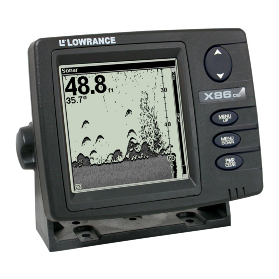
- Page 1 Pub. 988-0151-411 www.lowrance.com X86 DS & X86 TX Fish-finding & Depth Sounding Sonars Installation and Operation Instructions...
- Page 2 All features and specifications subject to change without notice. All screens in this manual are simulated. On the cover: X86 DS shown. For free owner's manuals and the most current information on this product, its operation and accessories, visit our web site: www.lowrance.com...
-
Page 3: Table Of Contents
Section 1: Introduction...1 Specifications: X86 DS and X86 TX ...1 How Sonar Works...2 Preparations ...3 Section 2: Installation & Accessories...5 Recommended Tools and Supplies ...5 Selecting a Transducer Location ...5 How low should you go? ...6 Shoot-thru-hull vs. Transom Mounting ...7 Transom Transducer Assembly and Mounting ...8... - Page 4 Depth Display...41 Temperature Display ...41 Voltage ...42 Units...42 Backlight...43 Contrast ...43 Simulator ...44 Set Language ...44 Software Information...44 Reset Options...44 Troubleshooting...45...
-
Page 5: Section 1: Introduction
Then, read the rest of the manual. The more you know about your sonar, the better it will work for you. Capabilities and Specifications: X86 DS and X86 TX Case size:... 5.4" H x 6.9" W x 3.4" D (13.8 cm H x 17.6 cm Display: ...4.5"... -
Page 6: How Sonar Works
Depth capability: ...To 1,000 feet (305 meters) with 83 kHz. Ac- Depth display: ...Continuous display. Audible alarms: ...Deep/shallow/fish/battery. Automatic ranging: ...Yes. Auto bottom track: ...Yes. Zoom bottom track:...Yes. Surface water temp: ...Yes. NOTICE! The storage temperature for your unit is from -4 degrees to +167 degrees Fahrenheit (-20 degrees to +75 degrees Celsius). -
Page 7: Preparations
Dual Search Transducer Your unit is packed with a Dual Search Skimmer Transducer that can transmit at 83 kHz and 200 kHz. A new innovation, the 83 kHz frequency offers superior sonar perform- ance at all depths from very shallow up to 1,000 ft and provides up to 120º... - Page 8 Notes...
-
Page 9: Section 2: Installation & Accessories
Installation & Accessories These instructions will help you install your Skimmer transom, on a trolling motor or inside a hull. Please read all instruc- tions before proceeding with any installation. Your Skimmer transducer typically comes packaged with a one-piece stainless steel bracket for mounting it to the transom of your boat. The optional trolling motor mount uses a one-piece plastic bracket with an adjustable strap. -
Page 10: How Low Should You Go
NOTE: Some aluminum boats with strakes or ribs on the outside of the hull create large amounts of turbulence at high speed. These boats typically have large outboard motors capable of propelling the boat at speeds faster than 35 mph. Typically, a good location on alumi- num boats is between the ribs closest to the engine. -
Page 11: Shoot-Thru-Hull Vs. Transom Mounting
Transducer centerline Align transducer centerline with hull bottom. If you want to adjust the transducer slightly higher or lower, the slots in the mounting brackets allow you to loosen the screws and slide the transducer up or down. If you frequently lose bottom signal lock while running at high speed, the transducer may be coming out of the water as you cross waves or wakes. -
Page 12: Transom Transducer Assembly And Mounting
Lack of angle adjustment can be particularly troublesome on hulls that sit with the bow high when at rest or at slow trolling speeds. Third, a transducer CAN NOT shoot through wood and metal hulls. Those hulls require either a transom mount or a thru-hull installation. Fourth, if your Skimmer transducer has a built in temp sensor, it will only show the temperature of the bilge, not the water surface temp. - Page 13 If you can, then go to step 3. If it doesn't, repeat step 2, but use a dif- ferent alignment letter until you can place the transducer on the transom correctly. Ratchets Insert bolt and check transducer position on transom. 3.
- Page 14 Transom Transom Position transducer mount on transom and mark mounting holes. Side view (left) and shown from above (right). 5. Attaching transducer to transom. Remove the transducer from the bracket and re-assemble it with the cable passing through the bracket over the bolt as shown in the following figures. Route cable over bolt and through bracket.
-
Page 15: Trolling Motor Bracket Installation
6. Route the transducer cable through or over the transom to the sonar unit. Make sure to leave some slack in the cable at the transducer. If possible, route the transducer cable away from other wiring on the boat. Electrical noise from the engine's wiring, bilge pumps, VHF radio wires and cables, and aerators can be picked up by the sonar. -
Page 16: Transducer Orientation And Fish Arches
3. Route the transducer cable alongside the trolling motor shaft. Use plastic ties (not included) to attach the transducer cable to the troll- ing motor shaft. Make sure there is enough slack in the cable for the motor to turn freely. Route the cable to the sonar unit and the trans- ducer is ready for use. -
Page 17: Shoot-Thru-Hull Preparation
If only the back half of the arch is printed, then the nose of the trans- ducer is angled too far down and needs to be raised. NOTE: Periodically wash the transducer's face with soap and water to re- move any oil film. Oil and dirt on the face will reduce the sensitiv- ity or may even prevent operation. - Page 18 1. Anchor the boat in about 30 feet of water. Add a little water to the sump of the boat. Plug the transducer into the sonar unit, turn it on, then hold the transducer over the side of the boat in the water. Adjust the sensitivity and range controls until a second bottom echo is seen on the display.
-
Page 19: Shoot-Thru-Hull Installation
You will need to figure some way to prop the transducer into position while you make your test run. A brick or two might be sufficient to hold it in place. 5. When you are satisfied with a location, mark it and proceed with the installation. -
Page 20: Power And Cable Connections
WARNING: Use only the epoxy available from LEI. It has been for- mulated to work with these installation procedures. Other epoxy types may be too thin or may not cure to the right consistency for optimum transducer perform- ance. 2. The epoxy consists of the epoxy itself and a hardener. Remove the two compounds from the package and place them on the paper plate. - Page 21 ble to the auxiliary power switch included in most boat designs. If that results in electrical interference, or if such a switch is not available, we recommend connecting direct to the battery and in- stalling an inline switch. This will let you shut off power to the power cable when the unit is not in use.
-
Page 22: Mounting The Sonar Unit: In-Dash Or Bracket
You can install the sonar unit on the top of a dash with the supplied bracket. It can also be installed in the dash with an optional dash- mounting kit. The FM-5 mount kit will work for both the X86 DS and X86 TX. -
Page 23: Bracket Installation
In-dash mounting template for X86 DS & X86 TX, showing dimensions. The preceding figure is not printed to scale. A scaled template is avail- able for free download from our web site, www.lowrance.com. Bracket Installation Mount the unit in any convenient location, provided there is clearance when it’s tilted for the best viewing angle. - Page 24 173.9 [6.85] 137.9 [5.43] Millimeter [Inch] Front view (left) and side view (right) showing dimensions of sonar Drill a 5/8" (15.9 mm) hole in the dash for the power/transducer cable. The best location for this hole is immediately under the gimbal bracket location.
-
Page 25: Portable Installation
Front Install the gimbal bracket. Orient the bracket so the arms slope to- ward the front of your unit. Attach the unit to the gimbal bracket using the supplied gimbal knobs and washers. Slide the rubber washers onto the gimbal knobs then loosely screw the knobs into their sockets. -
Page 26: Portable Transducer Assembly
"D" cell battery Install batteries in power case battery adapter. Portable Transducer Assembly Recommended tools for installation include a slotted screw driver and two adjustable wrenches. Assemble the transducer and bracket as shown in the following figure. Attach the transducer to the bracket with the supplied hardware. Make sure there is one washer on each side of the transducer, inside the bracket. - Page 27 Bolt Washer Portable transducer assembly: rear view (left) and side view (right.) Clean the chosen area of the hull before attaching the suction cup. Lo- cate the transducer on the hull as shown in the following figure. Don't allow the bracket to extend below the hull, because water pressure against it can cause the suction cup to come off at speed.
- Page 28 Notes...
-
Page 29: Section 3: Operation
Section 3: Operation Keyboard Basics The unit sounds a tone when you press any key. Numbers in the figure correspond to key explanations below: Lowrance X86 DS 1. PWR/CLEAR In this manual, the Power/Clear key is referred to as . Press this key to turn the unit on and off. -
Page 30: Memory
3. UP & DOWN ARROWS (↑ ↓) These Up and Down arrow keys are referred to as ↓ (DOWN) ↑ (UP) this manual. You will use these keys to adjust most features and functions on your unit. Memory This unit has permanent memory that saves the following user settings when power is turned off: Units of Measure, Temp Size, Depth Size, Fish I.D. -
Page 31: Fastrack
In the following figure, the screen shows a depth range from 0 to 80 feet and the bottom depth is 36.9 feet, shown by the digital sonar. The water temperature is 34.5° F. Digital depth Water Temp Bottom signal Depth range at bottom of depth scale FasTrack... -
Page 32: Full Chart
Pages The Pages menu allows you to display a full sonar chart or a Flash- Graf. The FlashGraf is a split screen that displays the sonar chart on the left side of the screen with a flasher on the right. Pages menu with Sonar Chart selected (left). -
Page 33: Depth Range
Digital depth Water Temp Bait fish Bottom signal Depth range at bottom of depth scale Full Chart page showing digital depth (above) and temp (below). The Fish I.D. feature is turned off. Depth Range The unit automatically adjusts the depth range according to water con- ditions. -
Page 34: Zoom
Zoom The zoom feature enlarges all images on the screen by doubling (2X) or quadrupling (4X) the size of the echoes. When you activate the zoom command, the screen will be split in half with the zoomed area dis- played on the left. The normal view will be shown on the right side of the screen. -
Page 35: Sensitivity
Enlarged fish arches Zoom Range menu with the 40-80 foot zoom selected. Notice the win- dow on the left zoomed 2X. The zoom range, 40-80 feet, covers a 40-foot water segment. When zoomed in 2X, the zoom window will show 20 feet of the water column with echoes magnified to twice their normal size. - Page 36 You can change the sensitivity level whether you are in Auto Sensitivity mode or Manual Sensitivity mode. The adjustment method works the same in both modes, but provides slightly different results. To adjust sensitivity in Auto Mode: Repeatedly press MENU sitivity is set to Auto, then press scroll bar.
-
Page 37: Grayline
® Grayline Grayline lets you distinguish between strong and weak echoes. It al- lows you to tell the difference between a hard and soft bottom. For ex- ample, a soft, muddy or weedy bottom returns a weaker signal which is shown with a narrow line or no gray line at all. -
Page 38: Chart Speed
To change the Grayline level, repeatedly press scroll bar appears. Press scrolling on the screen will show the effects of the Grayline adjustment. If you reach the maximum or minimum level, a tone sounds alerting you to the limits. Press Chart Speed The speed at which echoes scroll across the screen is called the chart speed. -
Page 39: Fish I.d
or less). This frequency is the best choice for about 80 percent of the fresh and salt water sport fishing applications. When you get into very deep salt water, up to 1,000 feet, the 83 kHz frequency will work best. The 200 kHz transducer will give you better detail and definition, but less depth penetration. -
Page 40: Fishtrack
Individual tree limbs extending outward from a group of limbs are the hardest objects for the Fish I.D. feature to distinguish from fish. Fish arches Underwater scene in normal fish arch mode (left). Fish I.D. menu with To see what is under your boat in maximum detail, we recommend you turn off Fish I.D. -
Page 41: Alarms
If you want to turn off FishTrack depths, but leave Fish I.D. on, press to select , then press to use the FishTrack feature. Fish ID menu and symbol with FishTrack on. The fish is 44 feet deep. Alarms Your sonar unit has four alarms: fish, shallow, deep and battery. NOTE: When one of the alarms is triggered, press the the alarm. -
Page 42: Depth Alarms
Depth Alarms The depth alarms are triggered only by the bottom signal. No other echoes will activate these alarms. The depth alarms consist of a shal- low and a deep alarm. The shallow alarm sounds an alarm when your vessel enters water that is more shallow than the alarm's setting. The deep alarm sounds a tone your vessel enters water that is deeper than the alarm's setting. -
Page 43: Deep Alarm
Deep Alarm menu (left). Deep Alarm dialog box (right). Deep Alarm To set the deep alarm depth, repeatedly press appears. Press the ↓ to enter the first number in the dialog box, then press ↓ to move to the next digit. Repeat those steps until the desired DOWN depth has been entered in the dialog box. -
Page 44: Noise Rejection And Asp
Press the ↓ appear. Input a voltage value between 7 and 18 volts. Use the to enter the first number in the dialog box, then press move to the next digit. Repeat those steps until the desired value has been entered in the dialog box. To move the cursor back to any of the previously entered numbers, press the Battery Alarm menu. -
Page 45: Depth Display
setting. There are times when you may want to turn off ASP. This al- lows you to view all incoming echoes before they are processed by the ASP feature. To change the ASP setting, repeatedly press menu appears. Use EJECTION to clear the menu. -
Page 46: Voltage
Temperature menu (left). Temperature display set to small size (right). Voltage The Voltage menu allows you to display battery voltage on the screen in a small or medium size or can be turned off completely. To display voltage: Repeatedly press until the menu appears. -
Page 47: Backlight
Units set to Feet, which displays temperature in Fahrenheit (left). Units set to Meters, which shows the temperature in Celsius. (right) Backlight The display's backlight allows the unit to be used at night. To turn the backlight on or off, repeatedly press until the menu MENU... -
Page 48: Simulator
Simulator This unit has a built-in simulator that shows simulated sonar returns with fish signals. This lets you practice with the unit as if you were on the water. All the unit's functions and features are usable in simulator mode. To use the simulator, repeatedly press until the menu... -
Page 49: Troubleshooting
Troubleshooting If your unit is not working, or if you need technical help, please use the following troubleshooting section before contacting the factory cus- tomer service department. It may save you the trouble of returning your unit for repair. For contact information, refer to the last page, just inside the back cover of this manual. - Page 50 3. The water may be deeper than the sonar's ability to find the bottom. If the sonar can't find the bottom signal while it's in the automatic mode, the digital sonar display will flash continuously. It may change the range to limits far greater than the water you are in.
- Page 51 In severe cases, it can completely cover the screen with black dots, or cause the unit operate erratically, or not at all. To eliminate or minimize the effects of electrical noise, first try to de- termine the cause. With the boat at rest in the water, the first thing you should do is turn all electrical equipment on the boat off.
- Page 52 Notes...
- Page 53 "We," "our," or "us" refers to LOWRANCE ELECTRONICS, a division of LEI, the manu- facturer of this product. "You" or "your" refers to the first person who purchases this product as a consumer item for personal, family, or household use. We warrant this product against defects or malfunctions in materials and workmanship, and against failure to conform to this product's written specifications, all for one (1) year from the date of original purchase by you.
-
Page 54: How To Obtain Service
How to Obtain Service… …in the USA: We back your investment in quality products with quick, expert service and genuine Lowrance replacement parts. If you're in the United States and you have technical, return or repair questions, please con- tact the Factory Customer Service Department. Before any product can be returned, you must call customer service to determine if a return is necessary. -
Page 55: Accessory Ordering Information For All Countries
Accessory Ordering Information for all countries To order Lowrance GPS accessories such as computer cables or MMC cards, please contact: 1) Your local marine dealer or consumer electronics store. Most quality dealers that handle marine electronic equipment or other consumer electronics should be able to assist you with these items. -
Page 56: Visit Our Web Site
Visit our web site: Lowrance Pub. 988-0151-411 © Copyright 2006 All Rights Reserved Printed in USA 042006 Lowrance Electronics, Inc.
Need help?
Do you have a question about the X86 DS and is the answer not in the manual?
Questions and answers