Table of Contents
Advertisement
Advertisement
Table of Contents

Subscribe to Our Youtube Channel
Related Manuals for Anetic Aid QA3 21110


Summary of Contents for Anetic Aid QA3 21110
- Page 1 Document No. 992012. Issue 19 – 24.10.22...
- Page 2 Document No. 992012. Issue 19 – 24.10.22...
-
Page 3: Table Of Contents
Contents Page Introduction 1. Introduction 1.1. Warnings & Cautions 1.2. Intended Use & Contraindications . 1.3. Device Classification 1.4. Serial Number Label 1.5. Putting the Stretcher into Service . 1.6. Abridged Summary of Warnings and Cautions 2. Product Specifications 3. Patient Stretcher Product Functions 4. - Page 4 Contents Page 44. Product Maintenance 45. Label Identification Product Accessories 46. Product Accessories 47. Using the Optional Monitor Shelf with Removable Refreshment Tray (catalogue no. 21152) 48. Using an Optional Loose Transfusion Pole (catalogue no. 21161) 49. Using the Optional Storage Box (catalogue no. 21191) . Quick Debugging Guide for DRIVE Assist &...
-
Page 5: Introduction 1. Introduction
If the stretcher is damaged or faulty it must be taken out of use with immediate effect and the fault reported to Anetic Aid, your authorised dealer NOTE: or maintenance department. The stretcher must not be used until the damage or fault has been repaired. -
Page 6: Device Classification
If the stretcher is damaged or faulty it must be taken out of use with immediate effect and the fault reported to Anetic Aid, your authorised dealer or maintenance department. The stretcher must not be used until the damage or fault has been repaired. - Page 7 Incompatible mattresses can create hazards; only replace the mattress with a new mattress supplied by Anetic Aid, or your authorised dealer, to ensure compatibility in accordance with BS EN 60601-2-52:2010+A1:2015. Disinfectant products are corrosive in nature; failure to properly wash and dry the stretcher surfaces could leave a corrosive residue which may cause damage to the stretcher.
-
Page 8: Product Specifications
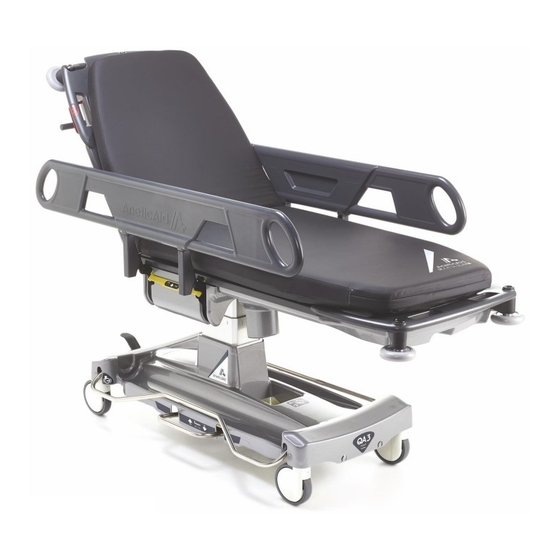
Product Specifications Product Specifications Fig. 1 Document No. 992012. Issue 19 – 24.10.22 Page 4... - Page 9 Product Specifications QA3 Patient Stretcher QA3 Emergency Stretcher Key to Fig. 1 (and build options) (and build options) Ø150mm Ø200mm Ø150mm Ø200mm Castor Diameter (5.9”) (7.9”) (5.9”) (7.9”) NOTE: Ø150mm are the standard option, Ø200mm is a build option. Height range (all stretchers): 475mm 520mm 535mm...
- Page 10 50kPa to 106kPa Environmental regulatory information; WEEE, waste batteries, etc.: For the latest information about Anetic Aid’s environmental policy, WEEE policy, and the safe disposal of this product, please refer to our website. NOTE: All dimensions quoted are subject to the following tolerances; angles ±5°, lengths and widths ±25mm, depths ±10mm.
-
Page 11: Patient Stretcher Product Functions
Product Functions Patient Stretcher Product Functions (21110) Key to Fig. 2 Backrest Actuation Lever. Trendelenburg Actuation Lever. Steering Pedal (activates 5 wheel). Brake Pedal. Raise and Lower Pedal. Side Rail. Side Rail Release Lever. Fixed Transfusion Pole. Fold-away Pushing Handles. Fixed Pushing Handles. -
Page 12: Emergency Stretcher Product Functions
Product Functions Emergency Stretcher Product Functions (21120, 21122, 21124 and 21126) Key to Fig. 3 - See Fig. 2 Patient Stretcher specification for standard features. Additional Fixed Transfusion Pole. ‘V’ Mounting for 1 Litre Suction Canister. X-Ray Platform. Document No. 992012. Issue 19 – 24.10.22 Page 8... -
Page 13: Drive Assist Product Functions
Product Functions DRIVE Assist Product Functions (21112, 21114, 21122 and 21124) Key to Fig. 4 - See Fig. 2 Patient Stretcher specification for standard features. Fold-away DRIVE assist Pushing Handles. Fixed DRIVE assist Pushing Handles. Charging Socket. Head End User Interface, see Fig. 13 in Section 19 for more details. Used on DRIVE Patient Stretcher (21112), DRIVE Emergency Stretcher (21122). -
Page 14: Powered Stretcher Product Functions
Product Functions Powered Product Functions (21114, 21116, 21124 and 21126) Key to Fig. 5 - See Fig. 2 Patient Stretcher specification for standard features. Head End User Interface, see Fig. 14 in Section 19 for more details. Used on DRIVE Powered Patient Stretcher (21114), DRIVE Powered Emergency Stretcher (21124). -
Page 15: Ophthalmic Stretcher Product Functions
Product Functions Ophthalmic Product Functions (21118) Key to Fig.6 - See Fig. 2 Patient Stretcher specification for standard features, and See Fig. 5 Powered Product specification for powered functions. Trendelenburg Actuation Levers; there are two levers, one on the patient left hand side of the trolley, and one on the patient right hand side. -
Page 16: Manual Functions
Manual Functions Introduction to Manual Functions This section of the document gives a description of product functions that are manually operated, and how to use them. Some of the manual functions are common across the product range, and are relevant to DRIVE, DRIVE Powered and Powered Stretchers. Height Adjustment The height of the patient platform is adjusted by using either of the raise and lower pedals (item 5, Fig.2). -
Page 17: Using The Backrest
Manual Functions When the IV pole is in use, the weight of the side rail is increased and the side rail may lower more quickly. Keep a firm grip on the side rail as it lowers to NOTES: control its movement; see Section 16, ‘Using the Transfusion Pole’, for details on the maximum weight for the IV pole. -
Page 18: Using The Transfusion Pole
Manual Functions 16. Using the Transfusion Pole The Patient Stretcher is supplied with one fixed transfusion pole fitted into the patient’s left hand side rail (item 8, Fig. 2). The Emergency Stretcher is fitted with two fixed transfusion poles, one on each side rail. To use the transfusion pole, as illustrated in Fig. -
Page 19: Additional Features Of An Emergency Stretcher
Manual Functions CAUTION: When folding the transfusion pole away ensure that it is fully retracted and returned to its storage position within the side rail; failure to do this may cause the pole to get caught on obstructions when pushing the stretcher. -
Page 20: Using The Dual-Articulating Head Positioner (Qa3 Ophthalmic Stretcher Only)
Manual Functions 18. Using the Dual-articulating Head Positioner (QA3 Ophthalmic Trolley only) The stretcher is designed to allow for different head section options to be fitted; the image below shows the ‘Dual-articulating Head Positioner’ (see Section 45. Product Accessories, for optional head sections). To remove the head section, lift the release handle Fig. -
Page 21: Drive Assist Function
DRIVE Assist Function Introduction to DRIVE Assist This section of the document explains what DRIVE assist means, and how to use it. The stretcher incorporates a motorised 5 wheel, the ‘DRIVE wheel’. The assistance the DRIVE wheel provides is to help reduce the pushing and pulling forces required to start and stop the stretcher, and the force required in motion;... -
Page 22: Drive Assist Handle Calibration
DRIVE Assist Function DRIVE Assist Handle Calibration When the stretcher is switched on, the system status indicator (item 2, Fig. 13) will flash for 1-3 seconds indicating that the DRIVE handles are calibrating. The indicator will turn solid green when calibration is successful and another short beep will sound; the DRIVE handles are now active. -
Page 23: Drive Assist Handle Deactivation And Automatic Switch Off
DRIVE Assist Function WARNING: Do not stow the fold-away handles when driving, or whilst DRIVE assist is active. Ensure the brakes are engaged before stowing the fold-away handles. WARNING: When leaving a patient unattended, always switch off the DRIVE assist function and apply the brakes. DRIVE Assist Handle Deactivation &... - Page 24 DRIVE Assist Function of standstill, the wheel brake will disengage to allow the stretcher to be manoeuvred without using the DRIVE handles. If you release the stretcher on flat ground, the DRIVE wheel brake will slow the stretcher to a stop within a few metres. ...
-
Page 25: Powered Functions
Powered Functions Introduction to Powered Functions This section of the document gives a description of product functions that are electrically Powered and button operated, and how to operate them. Powered features are available on the following stretchers; Powered Patient Stretcher (21116), Powered Emergency Stretcher (21126), DRIVE Powered Patient Stretcher (21114) and DRIVE Powered Emergency Stretcher (21124), Ophthalmic Stretcher (21118). -
Page 26: Switching On Powered Functions
Powered Functions Key to Fig. 16 - User Interface (foot end), used on the following products; Powered Patient Stretcher (21116), DRIVE Powered Patient Stretcher (21114), Ophthalmic Stretcher (21118) 11 & 12. Raise KneeFlex / Lower KneeFlex 13 & 14. Raise Backrest and KneeFlex simultaneously / Lower Backrest and KneeFlex simultaneously CPR Position Button (lower patient platform, backrest and KneeFlex simultaneously) -
Page 27: Using The Emergency Stop Button
Powered Functions Using the Emergency Stop Button The emergency stop button is located at the foot end of the stretcher beneath the user interface, see (A) in Fig. 17. The emergency stop button is used to deactivate all of the powered functions in the unlikely event of a powered function auto-actuating. -
Page 28: Common Product Information
Identification) to identify that an 800mm wide mattress must be fitted. WARNING: Incompatible mattresses can create hazards; only replace the mattress with a new mattress supplied by Anetic Aid, or your authorised dealer, to ensure compatibility in accordance with BS EN 60601-2-52:2010. -
Page 29: Fitting A Replacement Mattress Cover
Common Product Information Judith Waterlow The mattress is rated as medium to high risk and suitable for the Score majority of patients up to 23 hours. It is important to remain aware of individual patient needs, and standard nursing practices must always apply for patients immobile or at high risk of pressure sores. -
Page 30: Product Warranty
Anetic Aid or their approved distributor. Anetic Aid will repair or replace, at their discretion, any components found to be defective or at variance with the manufacturer’s specification within this time at... -
Page 31: Label Identification
Common Product Information 45. Label Identification The following list is a description of all the labels used on the stretcher; Serial number label. Maximum patient weight limit is 320kg (705.5lbs), and the stretcher safe working load is 320kg (705.5lbs). Depress the brake pedal to brake all four castors. - Page 32 Common Product Information Pull up on the Trendelenburg actuation lever to adjust the patient platform angle. The IV pole must be fully inserted into the mounting socket to be locked into the vertical position. The maximum weight per hook is 3kg (6.6lbs) and the safe working load for the IV pole is 6kg (13.2lbs).
- Page 33 Common Product Information The screen printed Anetic Aid brand logo with multiple information symbols; ‘K8 Pressure Care’ technology, CE marked, refer to the instructions for use, UKCA, mattress is x-ray translucent, latex free, compliant Fire Crib Test BS7177:2008 for medium hazard.
- Page 34 Common Product Information QA3 Emergency Stretcher branding label. QA3 Ophthalmic Stretcher branding label. DRIVE branding. Powered branding. DRIVE Powered branding. Ophthalmic branding. Document No. 992012. Issue 19 – 24.10.22 Page 30...
-
Page 35: Product Accessories
Product Accessories 46. Product Accessories Code Description QA3 Patient Stretcher System 21110 QA3™ Patient Stretcher - includes K8 Pressure Care Mattress QA3™ DRIVE Patient Stretcher - includes K8 Pressure Care Mattress 21112 QA3™ DRIVE Powered Patient Stretcher - includes K8 Pressure Care 21114 Mattress 21118... - Page 36 Product Accessories Document No. 992012. Issue 19 – 24.10.22 Page 32...
-
Page 37: Using An Optional Loose Transfusion Pole (Catalogue No. 21161)
Product Accessories The monitor shelf frame can be fitted with two transfusion poles (catalogue no. 21152- B1) as a factory fitted option. The height of the transfusion pole is adjusted by releasing the thumb lock (D), lifting the pole to the desired height, and retightening the thumb lock. -
Page 38: Quick Debugging Guide For Drive Assist & Powered Functions
Quick Debugging Guide for DRIVE Assist & Powered Functions 50. Quick Debugging Guide for DRIVE Assist In case your DRIVE assist system fails to perform as expected, follow these steps; 50.1. Check if the system is switched on; the system switches off automatically after 30 minutes of inactivity. - Page 39 Quick Start Guide for DRIVE Assist This ‘quick start guide’ is intended to help you use the DRIVE assist function in a few simple steps. However, it is advisable that the full Instructions for Use are read thoroughly before using the equipment. Engage the DRIVE wheel;...
- Page 40 Document No. 992012. Issue 19 – 24.10.22 Page 36...
Need help?
Do you have a question about the QA3 21110 and is the answer not in the manual?
Questions and answers