Anetic Aid QA4 Operating Instructions Manual
Surgery trolley system - powered function, version 2
Hide thumbs
Also See for QA4:
- Instructions for use manual (28 pages) ,
- Instructions for use manual (8 pages) ,
- Instructions for use manual (20 pages)
Table of Contents

Related Manuals for Anetic Aid QA4


Summary of Contents for Anetic Aid QA4
- Page 1 QA4 Surgery Trolley System – Powered Function, Version 2 Operating Instructions Catalogue No. 21300 Anetic Aid Ltd. Queensway Guiseley West Yorkshire, LS20 9JE United Kingdom T +44 (0) 1943 878647 F +44 (0) 1943 870455 www.aneticaid.com...
-
Page 2: Table Of Contents
QA4 Surgery Trolley System – Powered Function, Version 2 Operating Instructions Contents Page 1. Introduction 1.1. Warnings and Cautions 1.2. Scope of Use 1.3. Equipment Classification 2. Product Specifications 3. Product Functions 3.1. Powered Trolley Functions 3.1.1. Using the Handset 3.1.2. -
Page 3: Introduction
QA4 Surgery Trolley System – Powered Function, Version 2 Operating Instructions 1. Introduction These instructions are intended to assist you with the operation of the QA4 day surgery trolley. It is important that these instructions are read thoroughly before using the equipment. -
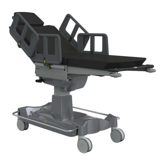
Page 4: Product Specifications
QA4 Surgery Trolley System – Powered Function, Version 2 Operating Instructions 2. Product Specifications Fig. 1 Key to Fig. 1 Height, MIN Weight Limits; 680 mm Height, MAX 1080 mm Trolley 250 kg Mattress Length 2040 mm Head Section 25 kg... -
Page 5: Product Functions
QA4 Surgery Trolley System – Powered Function, Version 2 Operating Instructions 3. Product Functions Fig. 2 Key to Fig. 2 Handset Brake Pedals Steering Pedal Lateral Tilt Handle Head Section Tilt Actuation Lever Removable Leg Section Cotsides Pushing Handles Oxygen Cylinder Mounting Trough ‘V’... -
Page 6: Powered Trolley Functions
QA4 Surgery Trolley System – Powered Function, Version 2 Operating Instructions 3.1. Powered Trolley Functions 3.1.1. Using the Handset The following four trolley functions are The handset is externally removable and electromechanical in operation and are plugs into the handset socket on the... -
Page 7: Using The Backrest
QA4 Surgery Trolley System – Powered Function, Version 2 Operating Instructions 3.1.3. Using the Backrest Observe that when the patient platform is traversed in either direction the mid The backrest can be raised and lowered section static frame arm is revealed. -
Page 8: Manual Trolley Functions
QA4 Surgery Trolley System – Powered Function, Version 2 Operating Instructions 3.1.5. Using the Trendelenberg CAUTION: The steering wheel must be disengaged manually when the trolley is Function pushed head first over an obstruction, i.e. patient platform a lift threshold, or damage may occur. -
Page 9: Using The Leg Section
QA4 Surgery Trolley System – Powered Function, Version 2 Operating Instructions 3.2.5. Using the Leg Section greater access to the patient from the head end for theatre staff. The trolley is fitted as standard with a non-articulating lightweight leg section Lower (no.6, fig.2), if the trolley is fitted with an... -
Page 10: Using The Cotsides
QA4 Surgery Trolley System – Powered Function, Version 2 Operating Instructions 3.2.5.3. Articulating Leg Section 3.2.6.2. Removing the Cotsides NOTE: The articulating leg section is an Ensure the cotside is in the ‘up’ position, optional accessory for this trolley. depress the button as indicated, see fig. - Page 11 QA4 Surgery Trolley System – Powered Function, Version 2 Operating Instructions 3.2.6.4. Attaching the Full Length will automatically relock in the down position. Cotside The optional full length cotside attaches to the trolley by hooking onto the side bar. To secure the cotside, rotate the locking clamp handle 90°...
- Page 12 QA4 Surgery Trolley System – Powered Function, Version 2 Operating Instructions 3.2.7.1. Releasing the Emergency correctly possibly disengaging unexpectedly. Backrest Handle 3.2.8. Using the Transfusion Pole The trolley is fitted with a loose transfusion pole (no.13, fig.2) that can be fitted at any point along the side bar and secured using the locking lever.
-
Page 13: Battery Charging And Battery Maintenance
QA4 Surgery Trolley System – Powered Function, Version 2 Operating Instructions NOTE: The maximum weight limit per IV fig.2). The socket should now be hook is 3kg or 3 litres, and the safe switched on. working load for the IV pole is 6kg. -
Page 14: Patient Weight Limits
QA4 Surgery Trolley System – Powered Function, Version 2 Operating Instructions prevent the side rail from locking when a ‘deep discharge’ condition. A normal 8 raised. hour charging period will not be sufficient to recover the battery. The battery will 7. -
Page 15: Product Maintenance
QA4 Surgery Trolley System – Powered Function, Version 2 Operating Instructions purchaser registering the product with Maximum patient weight limit is 250kg Anetic confirm receipt, and the trolley safe working load is 300kg. installation date and product details. The maximum load for the head section... - Page 16 QA4 Surgery Trolley System – Powered Function, Version 2 Operating Instructions Depress both leg section release buttons to remove the leg section. Unlocking the emergency backrest handle allows the user to lower the backrest in the event of an emergency.
- Page 17 NOTES...
- Page 18 NOTES...
- Page 19 NOTES...
Need help?
Do you have a question about the QA4 and is the answer not in the manual?
Questions and answers