Table of Contents
Advertisement
Quick Links
Advertisement
Table of Contents

Related Manuals for Moxa Technologies NPort 5200 Serie


Summary of Contents for Moxa Technologies NPort 5200 Serie
- Page 1 NPort 5200 Series User’s Manual Fifth Edition, September 2005 www.moxa.com/product Moxa Technologies Co., Ltd. Tel: +886-2-8919-1230 Fax: +886-2-8919-1231 Web: www.moxa.com MOXA Technical Support Worldwide: support@moxa.com.tw The Americas support@moxa.com...
-
Page 2: Copyright Notice
The software described in this manual is furnished under a license agreement and may be used only in accordance with the terms of that agreement. Copyright Notice Copyright © 2005 Moxa Technologies Co., Ltd. All rights reserved. Reproduction without permission is prohibited. -
Page 3: Table Of Contents
Table of Contents Chapter 1 Introduction ....................1-1 Overview ..........................1-2 Package Checklist......................... 1-2 Product Features ........................1-2 Product Specifications ......................1-3 Chapter 2 Getting Started ..................2-1 Panel Layout......................... 2-2 Connecting the Hardware ..................... 2-4 Wiring Requirements....................2-4 Connecting the Power....................2-4 Grounding NPort 5200 .................... - Page 4 Auto warning: Email and SNMP trap................. 5-27 Event Type........................5-28 Monitor..........................5-30 Monitor Line....................... 5-30 Monitor Async......................5-30 Monitor Async-Settings....................5-30 Change Password........................ 5-31 Load Factory Default......................5-31 Chapter 6 Configuring NPort Administrator.............6-1 Overview ..........................6-2 Installing NPort Administrator ..................... 6-2 Configuration........................
-
Page 5: Chapter 1 Introduction
Introduction Chapter 1 The NPort 5200 Series of advanced serial device servers make it easy to network enable your serial devices. The NPort 5200 Series includes 4 models: NPort 5210/5210-T (2 ports for RS-232), NPort 5230/5230-T (1 port for RS-232; 1 port for RS-422/485), NPort 5232/5232-T (2 ports for RS-422/485), and NPort 5232I/5232I-T (2 ports for RS-422/485, with isolation protection). -
Page 6: Overview
NPort 5200 Series User’s Manual Introduction Overview NPort 5200 Series serial device servers are designed to make your industrial serial devices Internet ready in no time. The compact size of NPort 5200 device servers makes them the ideal choice for connecting your RS-232 (NPort 5210/5230/5210-T/5230-T) or RS-422/485 (NPort 5230/5232/ 5232I/5230-T/5232-T/5232I-T) serial devices—such as PLCs, meters, and sensors—to an IP-based Ethernet LAN, making it possible for your software to access serial devices from... -
Page 7: Product Specifications
NPort 5200 Series User’s Manual Introduction Product Specifications Ethernet 10/100 Mbps, RJ45 Protection Built-in 1.5 KV magnetic isolation Serial Interface—NPort 5210/5210-T Interface RS-232 No. of Ports Port Type RJ45 (8-pin) Signals TxD, RxD, RTS, CTS, DTR, DSR, DCD, GND Serial Line Protection 15 KV ESD for all signals Serial Interface—NPort 5230/5230-T Interface... - Page 8 NPort 5200 Series User’s Manual Introduction Serial Communication Parameters Parity None, Even, Odd, Space, Mark Data Bits 5, 6, 7, 8 Stop Bit 1, 1.5, 2 Flow Control RTS/CTS (for RS-232 ports only), XON/XOFF Transmission Speed 110 bps to 115.2 Kbps Software Features Protocols ICMP, IP, TCP, UDP, DHCP, BOOTP, Telnet, DNS, SNMP,...
- Page 9 NPort 5200 Series User’s Manual Introduction Environmental Operating Temperature 0 to 55°C (32 to 131°F), 5 to 95%RH -40 to 75°C for “-T” versions Storage Temperature -20 to 85°C (-4 to 185°F), 5 to 95%RH Regulatory Approvals FCC Class A, CE Class A Safety UL, CUL, TÜV WARRANTY...
-
Page 10: Chapter 2 Getting Started
Getting Started Chapter 2 In this chapter, we give instructions on how to install the NPort 5200 device servers. Software installation is covered in subsequent chapters. The following topics are covered in this chapter: Panel Layout Connecting the Hardware Wiring Requirements Connecting the Power Grounding NPort 5200 Connecting to the Network... -
Page 11: Panel Layout
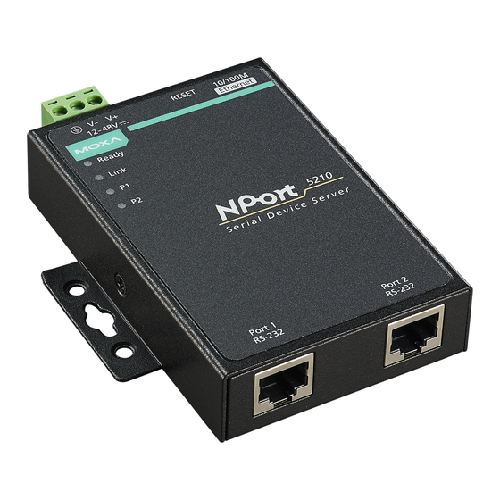
NPort 5200 Series User’s Manual Getting Started Panel Layout NPort 5210/5210-T NPort 5230/5230-T Top-end View Top-End View Terminal Block Terminal Block Power input Power input Reset button Reset button RJ45 10/100 Mbps Ethernet port RJ45 10/100 Mbps Ethernet port Nameplate View Nameplate View RESET 10/100M... - Page 12 NPort 5200 Series User’s Manual Getting Started NPort 5232/5232-T NPort 5232I/5232I-T Top-end View Top-end View Terminal Block Terminal Block Power input Power input Reset button Reset button RJ45 10/100 Mbps Ethernet port RJ45 10/100 Mbps Ethernet port Nameplate View Nameplate View RESET 10/100M RESET...
-
Page 13: Connecting The Hardware
NPort 5200 Series User’s Manual Getting Started Connecting the Hardware This section describes how to connect NPort 5200 to serial devices for first time testing purposes. We cover Wiring Requirements, Connecting the Power, Grounding NPort 5200 Series, Connecting to the Network, Connecting to a Serial Device, and LED Indicators. Wiring Requirements ATTENTION Safety First! -
Page 14: Connecting To The Network
NPort 5200 Series User’s Manual Getting Started ATTENTION This product is intended to be mounted to a well-grounded mounting surface such as a metal panel. SG: The Shielded Ground (sometimes called Protected Ground) contact is the left most contact of the 3-pin power terminal block connector when viewed from the angle shown here. -
Page 15: Initial Ip Address Configuration
Initial IP Address Configuration Chapter 3 When setting up your NPort 5200 for the first time, the first thing you should do is configure the IP address. This chapter introduces the methods that can be used to configure the device server’s IP address. -
Page 16: Initializing Nport 5200'S Ip Address
NPort 5200 Series User’s Manual Initial IP Address Configuration Initializing NPort 5200’s IP Address 1. Determine whether your NPort 5200 needs to use a Static IP or Dynamic IP (either DHCP or BOOTP application). 2. If NPort 5200 is used in a Static IP environment, you can use NPort 5200 Administration Suite, ARP, Web Console, Telnet Console, or Serial Console to configure the new IP address. -
Page 17: Telnet Console
NPort 5200 Series User’s Manual Initial IP Address Configuration Take the following steps to use ARP to configure the IP address: 1. Obtain a valid IP address for your NPort 5200 from your network administrator. 2. Obtain NPort 5200’s MAC address from the label on its bottom panel. 3. - Page 18 NPort 5200 Series User’s Manual Initial IP Address Configuration 3. When the Telnet window opens, if you are prompted to input the Console password, input the password and then press Enter. Note that this page will only appear if the NPort 5200 is password protected. 4.
- Page 19 NPort 5200 Series User’s Manual Initial IP Address Configuration 6. Use the Backspace key to erase the current IP address, type in the new IP address, and then press Enter. 7. Press any key to continue.
-
Page 20: Serial Console (19200, N, 8, 1)
NPort 5200 Series User’s Manual Initial IP Address Configuration 8. Type m and then press Enter to return to the main menu. 9. Type s and then press Enter to Save/Restart the system. 10. Type y and then press Enter to save the new IP address and restart the NPort 5200. Serial Console (19200, n, 8, 1) You may use the RS-232 console port to set up the IP address for NPort 5200. - Page 21 NPort 5200 Series User’s Manual Initial IP Address Configuration ATTENTION The Serial Console can only be accessed by NPort 5200’s RS-232 ports (ports 1 and 2 for NPort 5210, and port 1 for NPort 5230). Since NPort 5232 and NPort 5232I do not have an RS-232 interface, the Serial Console program cannot be used to configure NPort 5232/5232I’s IP address.
- Page 22 NPort 5200 Series User’s Manual Initial IP Address Configuration 7. NPort 5200 will switch automatically from data mode to console mode as it receives a continuous “ ` ”string. 8. Input the password when prompted. Note that this page will only appear when the NPort 5200 has been set up for password protection.
-
Page 23: Choosing The Proper Operation Mode
Choosing the Proper Operation Mode Chapter 4 In this chapter, we describe the various NPort 5200 operation modes. The options include “Driver Mode,” which uses a driver installed on the host computer, and operation modes that rely on TCP/IP socket programming concepts. After reading this chapter, choose the operation mode most suitable for your application, and then refer to Chapter 5 for detailed instructions on how to configure the operation mode’s parameters. -
Page 24: Overview
NPort 5200 Series User’s Manual Choosing the Proper Operation Mode Overview NPort 5200 serial device servers network-enable traditional RS-232/422/485 devices. A serial device server is a tiny computer equipped with a CPU, real-time OS, and TCP/IP protocols that can bi-directionally transform data between the serial and Ethernet formats. By incorporating serial device servers in your application, you will be able to access, manage, and configure remote facilities and equipment over the Internet from anywhere in the world. -
Page 25: Tcp Server Mode
NPort 5200 Series User’s Manual Choosing the Proper Operation Mode ATTENTION The driver used for Real COM Mode is bundled with NPort Administrator. The driver is installed on your computer automatically when you install NPort 5200 Administration Suite. One of the major conveniences of using Real COM Mode is that Real COM Mode allows users to continue using RS-232/422/485 serial communications software that was written for pure serial communications applications. -
Page 26: Tcp Client Mode
NPort 5200 Series User’s Manual Choosing the Proper Operation Mode TCP Client Mode In TCP Client Mode, NPort 5200 can actively TCP Client Mode establish a TCP connection with a pre-determined host computer when serial data arrives. After the data has been transferred, NPort 5200 can disconnect automatically from the host computer by using the TCP alive check time or TCP/IP... -
Page 27: Reverse Telnet Mode
NPort 5200 Series User’s Manual Choosing the Proper Operation Mode Reverse Telnet Mode Console management is commonly used upon Console/AUX or COM port of routers, switches, and UPS. Rtelnet works the same as RAW mode that they only listen to one specific TCP port after booting up, and wait for the host on the network to initiate the connection. -
Page 28: Chapter 5 Web Console Configuration
Web Console Configuration Chapter 5 The Web Console is the most user-friendly method available to configure NPort 5200. In this chapter, we introduce the Web Console function groups and function definitions. The following topics are covered in this chapter: Opening Your Browser Basic Settings Network Settings Serial Settings... -
Page 29: Opening Your Browser
NPort 5200 Series User’s Manual Web Console Configuration Opening Your Browser Open your browser with the cookie function enabled. (To enable your browser for cookies, right click on your desktop Internet Explorer icon, select Properties, click on the Security tab, and then select the three Enable options as shown in the figure below.) Type 192.168.127.254 in the Address input box (use the correct IP address if different from the default), and then press Enter. - Page 30 NPort 5200 Series User’s Manual Web Console Configuration ATTENTION Refer to Chapter 3, Initial IP Address Configuration, to see how to configure the IP address. Examples shown in this chapter use the Factory Default IP address (192.168.127.254). The NPort 5200 homepage will open next. On this page, you can see a brief description of the Web Console’s nine function groups.
-
Page 31: Basic Settings
NPort 5200 Series User’s Manual Web Console Configuration Basic Settings Server name Setting Factory Default Necessity 1 to 39 characters [model name]_[Serial No.] Optional This option is useful for specifying the location or application of different NPort 5200s. Time NPort 5200 has a built-in Real-Time Clock for time calibration functions. Real-time information can be added to Auto warning “Email”... - Page 32 NPort 5200 Series User’s Manual Web Console Configuration Time server Setting Factory Default Necessity IP Address or Domain Name blank Optional (E.g., 192.168.1.1, time.stdtime.gov.tw, or time.nist.gov) NPort 5200 uses SNTP (RFC-1769) for auto time calibration. Input the correct “Time server” IP address or domain name. Once NPort 5200 is configured with the correct Time server address, NPort 5200 will request time information from the “Time server”...
-
Page 33: Network Settings
NPort 5200 Series User’s Manual Web Console Configuration Network Settings You must assign a valid IP address to NPort 5200 before it will work in your network environment. Your network system administrator should provide you with an IP address and related settings for your network. - Page 34 NPort 5200 Series User’s Manual Web Console Configuration Netmask Setting Factory Default Necessity E.g., 255.255.255.0 255.255.255.0 Required A netmask identifies a local area network. When a packet is sent out over the network, the NPort 5200 will use the subnet mask to check whether the destination TCP/IP host specified in the packet is on the local network segment.
-
Page 35: Snmp Settings
NPort 5200 Series User’s Manual Web Console Configuration SNMP Settings Community name Setting Factory Default Necessity 1 to 39 characters public Optional (E.g., Support, 886-89191230 #300) A community name is a plain-text password mechanism that is used to authenticate queries weakly to agents of managed network devices. -
Page 36: Serial Settings
NPort 5200 Series User’s Manual Web Console Configuration Auto report period Setting Factory Default Necessity Time interval (in seconds) Optional Serial Settings Click on Serial Settings, located under Main Menu, to display serial port settings for ports 1 and 2. To modify serial settings for a particular port, click on either Port 1 or Port 2 under Serial Settings, located under Main Menu on the left side of the browser window. -
Page 37: Serial Parameters
NPort 5200 Series User’s Manual Web Console Configuration Serial Parameters ATTENTION Check your serial device’s user’s manual to determine the proper settings for the device’s serial communication parameters. Use these settings to configure NPort 5200’s serial parameters. Baud rate Setting Factory Default Necessity 110 bps to 230.4 Kbps... -
Page 38: Operating Settings
NPort 5200 Series User’s Manual Web Console Configuration Operating Settings Click on Operating Settings, located under Main Menu, to display the operating settings for both of NPort 5200’s serial ports. Real COM Mode TCP alive check time Setting Factory Default Necessity 0 to 99 min 7 min... - Page 39 NPort 5200 Series User’s Manual Web Console Configuration Max connection is usually used when the user needs to receive data from different hosts simultaneously. The factory default is 1. In this case, only one specific host can access this port of the NPort 5200, and the Real COM driver on that host will have full control over the port.
- Page 40 NPort 5200 Series User’s Manual Web Console Configuration Delimiter 1 Setting Factory Default Necessity 00 to FF (hex) Required Delimiter 2 Setting Factory Default Necessity 00 to FF (hex) Required Once the NPort 5200 receives both delimiters through its serial port, it immediately packs all data currently in its buffer and sends it to the NPort 5200’s Ethernet port.
-
Page 41: Tcp Server Mode
NPort 5200 Series User’s Manual Web Console Configuration If the user wants to send a series of characters in the same packet, the serial device attached to NPort 5200 should send that series of characters during a time interval less than the Force transmit timeout for NPort 5200, and the total length of data must be less than or equal to NPort 5200’s internal buffer size. - Page 42 NPort 5200 Series User’s Manual Web Console Configuration status between the NPort 5200 and remote host by sending “keep alive” packets periodically. If the remote host does not respond to the packet, NPort 5200 assumes that the connection was closed down unintentionally.
- Page 43 NPort 5200 Series User’s Manual Web Console Configuration Delimiter 1 Setting Factory Default Necessity 00 to FF blank Optional Delimiter 2 Setting Factory Default Necessity 00 to FF blank Optional Once the NPort 5200 receives both delimiters through its serial port, it immediately packs all data currently in its buffer and sends it out the NPort 5200’s Ethernet port.
-
Page 44: Tcp Client Mode
NPort 5200 Series User’s Manual Web Console Configuration Therefore, you should set Force transmit timeout to be larger than 8.3 ms, so in this case, it must be greater than or equal to 10 ms. If the user wants to send a series of characters in the same packet, the serial device attached to NPort 5200 should send that series of characters during a time interval less than the Force transmit timeout for NPort 5200, and the total length of data must be less than or equal to NPort 5200’s internal buffer size. - Page 45 NPort 5200 Series User’s Manual Web Console Configuration TCP alive check time Setting Factory Default Necessity 0 to 99 min 7 min Optional 0 min: TCP connection is not closed due to an idle TCP connection. 1 to 99 min: NPort 5200 closes the TCP connection automatically if there is no TCP activity for the given time.
- Page 46 NPort 5200 Series User’s Manual Web Console Configuration Delimiter 1 Setting Factory Default Necessity 00 to FF (hex) blank Optional Delimiter 2 Setting Factory Default Necessity 00 to FF (hex) blank Optional Once the NPort 5200 receives both delimiters through its serial port, it immediately packs all data currently in its buffer and sends it to the NPort 5200’s Ethernet port.
- Page 47 NPort 5200 Series User’s Manual Web Console Configuration If the user wants to send a series of characters in the same packet, the serial device attached to NPort 5200 should send that series of characters during a time interval less than the Force transmit timeout for NPort 5200, and the total length of data must be less than or equal to NPort 5200’s internal buffer size.
-
Page 48: Udp Mode
NPort 5200 Series User’s Manual Web Console Configuration Connect/Disconnect Description Startup/None A TCP connection will be established on startup, and will remain (default) active indefinitely. Any Character/None A TCP connection will be established when any character is received from the serial interface, and will remain active indefinitely. Any Character/ A TCP connection will be established when any character is received Inactivity Time... - Page 49 NPort 5200 Series User’s Manual Web Console Configuration Delimiter 1 Setting Factory Default Necessity 00 to FF blank Required Delimiter 2 Setting Factory Default Necessity 00 to FF blank Required Once the NPort 5200 receives both delimiters through its serial port, it immediately packs all data currently in its buffer and sends it out the NPort 5200’s Ethernet port.
-
Page 50: Pair Connection Mode
NPort 5200 Series User’s Manual Web Console Configuration If the user wants to send a series of characters in the same packet, the serial device attached to NPort 5200 should send that series of characters during a time interval less than the Force transmit timeout for NPort 5200, and the total length of data must be less than or equal to NPort 5200’s internal buffer size. -
Page 51: Pair Connection Slave Mode
NPort 5200 Series User’s Manual Web Console Configuration TCP alive check time Setting Factory Default Necessity 0 to 99 min Required 7 min 0 min: TCP connection is not closed due to an idle TCP connection. 1 to 99 min: NPort 5200 closes the TCP connection automatically if there is no TCP activity for the given time. -
Page 52: Reverse Telnet Mode
NPort 5200 Series User’s Manual Web Console Configuration Reverse Telnet Mode TCP alive check time Setting Factory Default Necessity 0 to 99 min Required 0 min: TCP connection is not closed due to an idle TCP connection. 1 to 99 min: NPort 5200 closes the TCP connection automatically if there is no TCP activity for the given time. -
Page 53: Disabled Mode
NPort 5200 Series User’s Manual Web Console Configuration Disabled Mode When Operation mode is set to Disabled, that particular port will be disabled. Check the “Apply the above settings to all serial ports” to apply this setting to the other port. Accessible IP Settings NPort 5200 uses an IP address based filtering method to control access to itself. -
Page 54: Auto Warning Settings
NPort 5200 Series User’s Manual Web Console Configuration Any host can access the NPort 5200 Disable this function by un-checking the “Enable the accessible IP list” checkbox. The following table shows six specific Accessible IP Settings rules. In the “Input format” column, “192.168.1.123 / 255.255.255.255”... -
Page 55: Event Type
NPort 5200 Series User’s Manual Web Console Configuration From E-mail address Setting Factory Default Necessity 1 to 63 characters blank Optional E-mail address 1/2/3/4 Setting Factory Default Necessity 1 to 63 characters blank Optional ATTENTION Consult your Network Administrator or ISP for the proper mail server settings. The Auto warning function may not work properly if it is not configured correctly. -
Page 56: Dcd Changed
NPort 5200 Series User’s Manual Web Console Configuration IP address changed The user has changed NPort 5200’s IP address. When the IP address changes, NPort 5200 will send an e-mail with the new IP address before NPort 5200 reboots. If the NPort 5200 is unable to send an e-mail message to the mail server within 15 seconds, NPort 5200 will reboot anyway, and abort the e-mail auto warning. -
Page 57: Monitor
NPort 5200 Series User’s Manual Web Console Configuration Monitor Monitor Line Click on Line under Monitor to show the operation mode and status of each connection (IPx), for each of the two serial ports. Monitor Async Click on Async under Monitor to show the current status of each of the two serial ports. Monitor Async-Settings Click on Async Setting under Monitor to show the run-time settings for each of the two serial ports. -
Page 58: Change Password
NPort 5200 Series User’s Manual Web Console Configuration Change Password Input the “Old password” and “New password” to change the password. Leave the password boxes blank to erase the password. Keep in mind that if the password is erased, then NPort 5200 will not have password protection. -
Page 59: Configuring Nport Administrator
Configuring NPort Administrator Chapter 6 The following topics are covered in this chapter: Overview Installing NPort Administrator Configuration Broadcast Search Unlock Password Protection Configuring NPort 5200 Upgrading the Firmware Export Configuration Import Configuration Monitor Port Monitor COM Mapping On-line COM Mapping Off-line COM Mapping IP Location... -
Page 60: Overview
NPort 5200 Series User’s Manual Configuring NPort Administrator Overview Device Server Administrator lets you install and configure your NPort 5200 Series products easily over the network. Five function groups are provided to ease the installation process, allow off-line COM mapping, and provide monitoring and IP location server functions. Device Server Administrator is an integrated software suite that bundles Device Server Administrator and the IP Serial Library, and provides everything you need to manage, monitor, and modify your NPort 5200 from a remote location. - Page 61 NPort 5200 Series User’s Manual Configuring NPort Administrator 3. Click on Next to install the program using the default program name, or select a different name. 4. Click on Install to proceed with the installation.
- Page 62 NPort 5200 Series User’s Manual Configuring NPort Administrator 5. The Installing window reports the progress of the installation. 6. Click on Next to proceed with the installation.
-
Page 63: Configuration
NPort 5200 Series User’s Manual Configuring NPort Administrator 7. Click on Finish to complete the installation of NPort 5200 Administration Suite. Configuration The Administrator-Configuration window is divided into four parts. The top section contains the function list and online help area. (Windows NT does not support this .chm file format.) The five Administrator function groups are listed in the left section. -
Page 64: Broadcast Search
NPort 5200 Series User’s Manual Configuring NPort Administrator Broadcast Search The Broadcast Search function is used to locate all NPort 5200s that are connected to the same LAN as your computer. Since the Broadcast Search function searches by MAC address and not IP address, all NPort 5200s connected to the LAN will be located, regardless of whether or not they are part of the same subnet as the host. -
Page 65: Unlock Password Protection
NPort 5200 Series User’s Manual Configuring NPort Administrator ATTENTION Before modifying NPort 5200’s configuration, use Broadcast Search to locate all NPort 5200s connected to the LAN, or use Specify by IP Address to locate a particular NPort 5200. Unlock Password Protection If the NPort 5200 is password protected (indicated by “Lock”... -
Page 66: Configuring Nport 5200
NPort 5200 Series User’s Manual Configuring NPort Administrator The meanings of the six “Status” states are given below (note that the term Fixed is borrowed from the standard fixed IP address networking terminology): Lock The NPort 5200 is password protected, “Broadcast Search” was used to locate it, and the password has not yet been entered from within the current Administrator session. - Page 67 NPort 5200 Series User’s Manual Configuring NPort Administrator 2. Unlock the NPort 5200 you wish to configure if it is password protected. Right click on the NPort 5200 and select Configure to start the configuration. 3. The progress bar shows that Administrator is retrieving configuration information from the specific NPort 5200.
-
Page 68: Upgrading The Firmware
NPort 5200 Series User’s Manual Configuring NPort Administrator 5. You will now be able to modify Time Zone, Local Date, Local Time, and Time Server. ATTENTION You can simultaneously modify the configurations of multiple NPort 5200s that are of the same model. - Page 69 NPort 5200 Series User’s Manual Configuring NPort Administrator 2. Unlock the NPort 5200 you wish to configure if it is password protected. Right click on a specific NPort 5200 and select the Upgrade Firmware function to start upgrading the firmware. 3.
-
Page 70: Export Configuration
NPort 5200 Series User’s Manual Configuring NPort Administrator Export Configuration To export the configuration of an NPort 5200, right click on the NPort 5200, select Export Configuration, and then follow the onscreen instructions. The Export Configuration function is a handy tool that can be used to produce a text file containing the current configuration of a particular NPort 5200. -
Page 71: Monitor
NPort 5200 Series User’s Manual Configuring NPort Administrator ATTENTION You can simultaneously import the same configuration file into multiple NPort 5200s that are of the same model. To select multiple NPort 5200s, hold down the Ctrl key when selecting an additional NPort 5200, or hold down the Shift key to select a block of NPort 5200s. - Page 72 NPort 5200 Series User’s Manual Configuring NPort Administrator Monitor Add Target Rescan 1. Click on Monitor under Function. 2. Click on Monitor Add Target from the menu bar, or click the right mouse button and select Add Target. 3. Click on Rescan. 6-14...
- Page 73 NPort 5200 Series User’s Manual Configuring NPort Administrator 4. Select your targets from the list, and then click on OK. Once the Monitor function is running: 1. The NPort 5200 list will appear on the Monitor screen. 2. Right click the panel and select Settings. 6-15...
- Page 74 NPort 5200 Series User’s Manual Configuring NPort Administrator 3. Select or de-select Monitor Items. Use the single arrowhead buttons to move highlighted items from one box to the other. Use the double arrowhead buttons to move all items in one box to the other.
- Page 75 NPort 5200 Series User’s Manual Configuring NPort Administrator 5. On the Advanced Settings page, select Display warning message for new event and/or Play warning music for new event. In the second case, you must enter the path to the WAV file that you want to be played.
- Page 76 NPort 5200 Series User’s Manual Configuring NPort Administrator 8. When one of the NPort 5200s loses connection with the Monitor program, a warning alert will display automatically. The warning music will be played at the same time. 9. In the Monitor screen, you can see that the NPort 5200s that are “Not Alive” are shown in red color.
-
Page 77: Port Monitor
NPort 5200 Series User’s Manual Configuring NPort Administrator 11. The NPort 5200s that were reconnected, and are now “Alive,” will be shown in black color. Port Monitor The process described here is the same as in the previous “Monitor” section. The only difference is that you can select more items under Port Monitor than under Monitor. -
Page 78: Com Mapping
NPort 5200 Series User’s Manual Configuring NPort Administrator COM Mapping Windows Administration Suite comes with Windows 95/98/ME/NT/2000/XP Real COM drivers. After you install NPort 5200 Administration Suite, there are two ways to set up the NPort 5200 serial port as your host’s remote COM port. The first way is with On-line COM Mapping. - Page 79 NPort 5200 Series User’s Manual Configuring NPort Administrator 3. Add the target to which you would like to map COM ports. 4. The NPort 5200 list that appears is the list generated by the previous Broadcast Search. Select the NPort 5200 to which you would like to map COM ports. 5.
- Page 80 NPort 5200 Series User’s Manual Configuring NPort Administrator 6. Select the COM No. COM ports that are “In use” or “Assigned” will also be indicated in this drop-down list. If you select multiple serial ports or multiple NPort 5200s, remember to check the “Auto Enumerating”...
- Page 81 NPort 5200 Series User’s Manual Configuring NPort Administrator • By default, the optional “Fast Flush” function is disabled. If you would like to enable this function, from the “NPort Administrator,” double click on the COM ports that are mapped to the NPort, and then select the “Fast Flush” checkbox. You should find that when “Fast Flush”...
- Page 82 NPort 5200 Series User’s Manual Configuring NPort Administrator 9. After setting the COM Mapping, remember to select Apply Change to save the information in the host system registry. The host computer will not have the ability to use the COM port until after Apply Change is selected.
-
Page 83: Off-Line Com Mapping
NPort 5200 Series User’s Manual Configuring NPort Administrator 11. To save the configuration to a text file, select Export COM Mapping. You will then be able to import this configuration file to another host and use the same COM Mapping settings in the other host. -
Page 84: Ip Location
NPort 5200 Series User’s Manual Configuring NPort Administrator 2. Modify the port settings as needed. 3. Right click in the NPort list section and select Apply Change. IP Location When NPort 5200 is used in a dynamic IP environment, users must spend more time with IP management tasks. - Page 85 NPort 5200 Series User’s Manual Configuring NPort Administrator 1. Configure NPort 5200 with Dynamic IP settings (DHCP, BOOTP, or DHCP/BOOTP). Assign the remote Auto IP report server’s IP address and UDP port. 2. Select IP Location Report and click the right mouse button to select Settings. 3.
- Page 86 NPort 5200 Series User’s Manual Configuring NPort Administrator 4. Click Go to start receiving the Auto IP address report from the NPort 5200 6-28...
-
Page 87: Ip Serial Lib
IP Serial LIB Chapter 7 The following topics are covered in this chapter: Overview IP Serial LIB Function Groups Example Program... -
Page 88: Overview
NPort 5200 Series User’s Manual IP Serial LIB Overview What is IP Serial Library? IP Serial Library is a Windows library with frequently used serial command sets and subroutines. IP Serial Library is designed to reduce the complexity and poor efficiency of serial communication over TCP/IP. -
Page 89: Ip Serial Lib Function Groups
NPort 5200 Series User’s Manual IP Serial LIB IP Serial LIB Function Groups Server Control Port Control Input/Output Data Port Status Miscellaneous Inquiry nsio_init nsio_open nsio_read nsio_lstatus nsio_break nsio_end nsio_close nsio_SetReadTimeouts nsio_data_status nsio_break_on nsio_resetserver nsio_ioctl nsio_write nsio_break_off nsio_checkalive nsio_flowctrl nsio_SetWriteTimeouts nsio_breakcount nsio_DTR nsio_RTS... -
Page 90: Appendix A Pinouts And Cable Wiring
Pinouts and Cable Wiring Appendix A The following topics are covered in this appendix: Port Pinout Diagrams Ethernet Port Pinouts Serial Port Pinouts Cable Wiring Diagrams Ethernet Cables Serial Cables... -
Page 91: Port Pinout Diagrams
NPort 5200 Series User’s Manual Pinouts and Cable Wiring Port Pinout Diagrams Ethernet Port Pinouts Signal Serial Port Pinouts 8-pin RJ45 RS-232 Port Pinouts for NPort 5210/5210-T RS-232 Terminal Block RS-232 & RS-422/485 Pinouts for NPort 5230/5230-T Serial Device NPort 5230 Signals Signals R+/D+ Tx+ / Data+... -
Page 92: Cable Wiring Diagrams
NPort 5200 Series User’s Manual Pinouts and Cable Wiring Cable Wiring Diagrams Ethernet Cables Straight-Through Cable RJ45 Plug Pin 1 Cable Wiring Cross-Over Cable RJ45 Plug Pin 1 Cable Wiring Serial Cables 8-pin RJ45 to DB25 Female for NPort 5210/5210-T (Cable Name: CBL-RJ45F25-150) RJ45 Port RJ45 Connector Female DB25... - Page 93 NPort 5200 Series User’s Manual Pinouts and Cable Wiring 8-pin RJ45 to DB25 Male for NPort 5210/5210-T (Cable Name: CBL-RJ45M25-150) RJ45 Port RJ45 Connector Male DB25 Female DB25 RS-232 NPort 5210 Device Cable Wiring 8 pins 25 pins 8-pin RJ45 to DB9 Female for NPort 5210/5210-T (Cable Name: CBL-RJ45F9-150) RJ45 Port RJ45 Connector Female DB9...
-
Page 94: Appendix B Well Known Port Numbers
Well Known Port Numbers Appendix B In this appendix, which is included for your reference, we provide a list of Well Known port numbers that may cause network problems if you set NPort 5200 to one of these ports. Refer to RFC 1700 for Well Known port numbers, or refer to the following introduction from the IANA. - Page 95 NPort 5200 Series User’s Manual Well Known Port Numbers TCP Socket Application Service (Login Host Protocol) (Login) Domain Name Server (domain) Finger protocol (Finger) World Wibe Web HTTP Netword news Transfer Protocol (NNTP) Network Time Protocol 160 – 223 Reserved for future use UDP Socket Application Service reserved...
- Page 96 SNMP Agents with MIB II & RS-232 Appendix C like groups NPort 5200 has built-in SNMP (Simple Network Management Protocol) agent software that supports SNMP Trap, RFC1317 RS-232 like groups and RFC 1213 MIB-II. The following table lists the standard MIB-II groups, as well as the variable implementation for NPort 5200. RFC1213 MIB-II supported SNMP variables: System MIB Interfaces MIB...
- Page 97 NPort 5200 Series User’s Manual Service Information System MIB Interfaces MIB IP MIB ICMP MIB SysServices ifInUnknownProtos ipReasmFails IcmpOutTimeExcds ifOutOctets ipFragOKs IcmpOutParmProbs ifOutUcastPkts ipFragFails IcmpOutSrcQuenchs ifOutNUcastPkts ipFragCreates IcmpOutRedirects ifOutDiscards ipAdEntAddr IcmpOutEchos ifOutErrors ipAdEntIfIndex IcmpOutEchoReps ifOutQLen ipAdEntNetMask IcmpOutTimestamps ifSpecific ipAdEntBcastAddr IcmpOutTimestampReps ipAdEntReasmMaxSize IcmpOutAddrMasks IpNetToMediaIfIndex...
- Page 98 NPort 5200 Series User’s Manual Service Information Address Translation MIB TCP MIB SNMP MIB AtNetAddress tcpRetransSegs snmpInTotalSetVars tcpConnState snmpInGetRequests tcpConnLocalAddress snmpInGetNexts tcpConnLocalPort snmpInSetRequests tcpConnRemAddress snmpInGetResponses tcpConnRemPort snmpInTraps tcpInErrs snmpOutTooBigs tcpOutRsts snmpOutNoSuchNames snmpOutBadValues snmpOutGenErrs snmpOutGetRequests snmpOutGetNexts snmpOutSetRequests snmpOutGetResponses snmpOutTraps snmpEnableAuthenTraps RFC1317: RS-232 MIB objects RS-232-like General Port RS-232-like Asynchronous Generic RS-232-like Group...
- Page 99 NPort 5200 Series User’s Manual Service Information The Input Signal Table The Output Signal Table rs232InSigTable rs232OutSigTable rs232InSigEntry rs232OutSigEntry rs232InSigPortIndex rs232OutSigPortIndex rs232InSigName rs232OutSigName rs232InSigState rs232OutSigState...
-
Page 100: Appendix D Auto Ip Report Protocol
Auto IP Report Protocol Appendix D NPort Series provides several ways to configure Ethernet IP addresses. One is DHCP Client. When you set up NPort to use DHCP Client to configure Ethernet IP addresses, it will automatically send a DHCP request over the Ethernet to find the DHCP Server. And then the DHCP Server will send an available IP address to the NPort. - Page 101 NPort 5200 Series User’s Manual Auto IP Report Protocol Auto IP Report Format “MOXA”, 4 bytes Info[0] Info[1] … Info[n] Info [n] Length Data Field Length Variable, Length is “Length Field” ID List ID Value Description Length Note Server Name Variable ASCII char Hardware ID...
-
Page 102: Appendix E Service Information
Service Information Appendix E This appendix shows you how to contact Moxa for information about this and other products, and how to report problems. In this appendix, we cover the following topics. MOXA Internet Services Problem Report Form Product Return Procedure... -
Page 103: Moxa Internet Services
NPort 5200 Series User’s Manual Service Information MOXA Internet Services Customer satisfaction is our number one concern, and to ensure that customers receive the full benefit of our products, Moxa Internet Services has been set up to provide technical support, driver updates, product information, and user’s manual updates. -
Page 104: Problem Report Form
NPort 5200 Series User’s Manual Service Information Problem Report Form MOXA NPort 5200 Series Customer name: Company: Tel: Fax: Email: Date: 1. Moxa Product: NPort 5210 NPort 5230 NPort 5232 NPort 5232I 2. Serial Number: _________________ Problem Description: Please describe the symptoms of the problem as clearly as possible, including any error messages you see. -
Page 105: Product Return Procedure
NPort 5200 Series User’s Manual Service Information Product Return Procedure For product repair, exchange, or refund, the customer must: Provide evidence of original purchase. Obtain a Product Return Agreement (PRA) from the sales representative or dealer. Fill out the Problem Report Form (PRF). Include as much detail as possible for a shorter product repair time.
Need help?
Do you have a question about the NPort 5200 Serie and is the answer not in the manual?
Questions and answers