Table of Contents
Advertisement
Quick Links
Advertisement
Table of Contents

Related Manuals for Kobold OMS


Summary of Contents for Kobold OMS
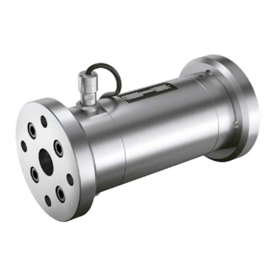
- Page 1 Operating Instructions Screw-Type Volumetric Flow Meter Model: OMS...
-
Page 2: Table Of Contents
Tightening torques and widths for threaded rings ......27 EU Declaration of conformance ..............28 Manufactured and Sold by: Kobold Messring GmbH Nordring 22-24 D-65719 Hofheim Tel.: +49(0)6192-2990 Fax: +49(0)6192-23398 E-Mail: info.de@kobold.com Internet: www.kobold.com page 2... -
Page 3: Note
Please read these operating instructions before unpacking and putting the unit into operation. Follow the instructions precisely as described herein. The instruction manuals on our website www.kobold.com are always for currently manufactured version of our products. Due to technical changes, the instruction manuals available online may not always correspond to the product version you have purchased. -
Page 4: General Information
The warranty is according to our terms of delivery. Repairs during the guarantee period must be carried out only by user or any other person authorised by us and in accordance with our agreement and instructions. page 4 OMS K01/0922... -
Page 5: Operating Principle
7. Operating Principle The measuring principle of the KOBOLD screw- volumeter is positive displacement. The flow of the fluid to be measured causes the measuring spindles M to rotate. With each rotation an exact volume is given. These rotations are being transmitted to the display A by the pole wheel P and pick up I. -
Page 6: Mechanical Connection
The thread length of the pipe should not be longer than the nection: thread length of the flowmeter (Stricture of the flow- diameter, damaging of internal parts). Storage: Improper storage may cause corrosion and seizing of internal parts. page 6 OMS K01/0922... -
Page 7: Electrical Connection
That could lead to incorrect measurements or even cause serious damage to the sensor system. OMS K01/0922 page 7... - Page 8 The dry shell G was built in, screwed in and tested as a unit with the sensor cartridge E at the KOBOLD factory. The dry shell G must not be moved out of position because that might cause the sensor signal to be lost or the volumeter to be damaged or functionally impaired.
-
Page 9: Disassembly And Assembly
Pumped liquids can be hot, poisonous, combustible and caustic. Observe the tightening torques, see Appendix, chapter 19. Observe the operating instructions and data sheets of the sensors. 10.1.1 Removing seals and bearings OMS-20/OMS-25 Personal qualification: Fitter ... - Page 10 672.1 and measuring screw small 672.2. Screw out the socket screws 915.6 and 915.7 and remove the wedge lock washers 904.1, 904.2 and supporting rings 064.1*** (only OMS-032) 064.2. Screw the socket screw 915.6 completely back in, in order to pull the pole wheel 259 and distance ring 056 from the measuring screw large 672.1 by...
- Page 11 259. Pull the wedge lock washers 904.1 and 904.2 and supporting rings 064.1*** (only OMS-032) and 064.2 onto the socket screws 915.6 and 915.7. Apply Loctite 242 to the socket screws 915.6 and 915.7, install on the...
- Page 12 128 using light blows of a plastic hammer and pull out. Screw out the socket screw 915.6 with wedge lock washer 904.1 and supporting ring 064.1 at the measuring screw large 672.1. Pull off the pole wheel 259 and distance ring 056. page 12 OMS K01/0922...
- Page 13 Remove the circlips 869.2 and 869.4 and the support rings 868.2 and 868.4 from the measuring screws. Pull the ball bearings 817.1 and 817.2 from the measuring screws by using the extractor. 10.1.4 Installing seals and bearings OMS-40 Personal qualification: Fitter ...
- Page 14 Press the ball bearings 817.2 on only over the inner ring on the measuring screw small 672.2. First screw in the threaded ring 057.2, then the threaded ring 057.1 into the bearing cover 080.1 using a torque wrench. For the widths and tightening torques, see Appendix, chapter 19. page 14 OMS K01/0922...
- Page 15 915.1 with torque, see Appendix, chapter 19. Install the flange cover. In the process pre-tighten the oiled screws crosswise and tighten with torque, see Appendix, chapter 19. OMS K01/0922 page 15...
-
Page 16: Start Up
11. Start up Technical data on the identification plate must be considered. Venting: The system must be free of air (affects the accuracy) page 16 OMS K01/0922... -
Page 17: Troubleshooting
Poor contacts Check the connection Interference sources from outside Make sure the cable (measuring Magnet transducer) is laid correctly wheel's separation distance not correct Check signal with oscilloscope. Correct the spacing OMS K01/0922 page 17... -
Page 18: Maintenance
13. Maintenance KOBOLD-volumeters are free of maintenance. At high bearing load it is useful to change the rolling bearings after a certain service life. When high accuracy is required, it is further advisable to calibrate the device peri- odically. page 18... -
Page 19: Technical Information
Accuracy Diagram The measuring error refers to the actual flow rate. The diagram shows the characteristic for the OMS-... screw-type volumetric flow meter. A test certificate is available because every device delivered is different. OMS K01/0922... - Page 20 OM.../44 Technical Details Pulse Generator Model System Voltage Material dry Electrical Protection face sleeve connection Hall-effect 10...30 V -40..+150°C 420 bar Arcap 3 m PTFE cable IP 67 page 20 OMS K01/0922...
-
Page 21: Order Details
15. Order Details Example: OMS-20F20401S4 Flow rate Code Process connection Pmax [bar] Pulses/L Frequency Gasket Bearing Pulse [l/min] [Hz] generator R20 = G ¾ 0,6-30 OMS-20 1200 4,0-200 F2040 = DN20/PN40 S = stainless R25 = G1 steel ball bearing... -
Page 22: Dimensions And Weights
16. Dimensions and Weights [mm] OMS Pipe thread version Model Connection Pressure Weight rating [mm] [mm] [mm] [mm] [kg] [bar] OMS-20R20… G¾ OMS-25R25… OMS-40R40… G1½ 27.5 page 22 OMS K01/0922... - Page 23 OMS Flange version Model Connection Pressure Weight rating [mm] [mm] [mm] [mm] [mm] [kg] [bar] OMS-20 F2040… DN20 PN40 20.5 OMS-25F3240… DN32 PN40 OMS-25F251S… DN25 PN160 OMS-40F4040… DN40 PN40 22.5 OMS K01/0922 page 23...
-
Page 24: Pressure Loss Diagram
17. Pressure loss diagram page 24 OMS K01/0922... -
Page 25: Disposal
(Cd, Hg, Li or Pb) of the heavy metal that is decisive for the classification as containing pollutants: 1. „Cd" stands for cadmium 2. „Hg" stands for mercury 3. „Pb" stands for lead 4. „Li" stands for lithium Electrical and electronic equipment OMS K01/0922 page 25... -
Page 26: Appendix
Tightening torque [Nm] Thread Galvanized + stainless steel G 1/8" 13.0 G 1/4" 30.0 G 3/8" 60.0 G 1/2" 80.0 G 3/4" G 1" G 1 1/4" G 1 1/2" Tightening torques, thread measured in inches page 26 OMS K01/0922... -
Page 27: Tightening Torques And Widths For Threaded Rings
19.3 Tightening torques and widths for threaded rings Size Measuring Item No. Width [mm] Tightening torque [Nm] screw OMS-052 Large 057.1 Small 057.2 Tightening torques and widths for threaded rings OMS K01/0922 page 27... -
Page 28: Eu Declaration Of Conformance
20. EU Declaration of conformance We, KOBOLD Messring GmbH, Hofheim-Ts, Germany, declare under our sole responsibility that the product: Screw-Type Volumetric Flow Meter Model: OMS to which this declaration relates is in conformity with the standards noted below: EN IEC 63000:2018 Technical documentation for the assessment of electrical...
Need help?
Do you have a question about the OMS and is the answer not in the manual?
Questions and answers