Table of Contents
Advertisement
Quick Links
P5-20...R40-17
Model: C18
Assembly and Operating Instructions
en
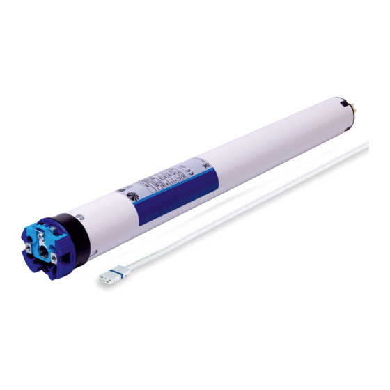
Tubular drive with integrated radio receiver for ZIP
systems
Important information for:
• Fitters / • Electricians / • Users
Please forward accordingly!
These instructions must be kept safe for future reference.
2010 300 901 0b 14/07/2022
Becker-Antriebe GmbH
Friedrich-Ebert-Straße 2-4
35764 Sinn/Germany
www.becker-antriebe.com
Advertisement
Table of Contents

Related Manuals for Becker C18 Series


Summary of Contents for Becker C18 Series
- Page 1 Tubular drive with integrated radio receiver for ZIP systems Important information for: • Fitters / • Electricians / • Users Please forward accordingly! These instructions must be kept safe for future reference. 2010 300 901 0b 14/07/2022 Becker-Antriebe GmbH Friedrich-Ebert-Straße 2-4 35764 Sinn/Germany www.becker-antriebe.com...
-
Page 2: Table Of Contents
Table of contents General .................................... 3 Warranty ..................................... 3 Safety instructions ................................ 4 Instructions for the user.............................. 4 Instructions for installation and commissioning........................ 4 Intended use .................................. 6 Assembling and disassembling the plug-in connecting cable.................... 6 Assembly .................................... 7 First operation .................................. 9 Programming the master transmitter .......................... -
Page 3: General
General These tubular drives are high-quality products with the following features: • Optimised for vertical ZIP applications • Individual, group and central radio control • No need to run wires to a switch or relay control device • Any combination of drive and transmitter possible •... -
Page 4: Safety Instructions
Safety instructions The following safety instructions and warnings are intended to avert hazards and to prevent property damage and personal injury. Instructions for the user General information • The drive must be disconnected from its power source during cleaning and maintenance and when re- placing parts. - Page 5 • If the drive is used for shading solutions in a specially marked area (e.g., escape routes, hazard zones, safety areas), compliance with all applicable regulations and standards must be ensured. • Once the drive has been installed, the fitter must mark the used tubular drive in the “Technical data” chapter and make a note of the installation position.
-
Page 6: Intended Use
Intended use The type of tubular drive described in these instructions is intended solely for the operation of vertical ZIP systems. It may only be used in networked systems if all the individual drives are exactly synchronised and reach their limit positions at the same time. -
Page 7: Assembly
Ø45/Ø58 Insert a suitable flathead screwdriver right into the recess of the locating latch, so that the latch releases the locating lug from the plug. Now you can pull out the connecting cable along with the flat- head screwdriver. A = locating latch Assembly Assembling the drive Attention... - Page 8 Assembling the drive adapter with safety catch on the Disassembling the drive adapter with safety catch on the drive shaft drive shaft Assembling and disassembling the drive adapter with drive adapter safety catch or screw connection Assembling and disassembling the drive Assembling and disassembling the drive adapter with separate drive adapter adapter with screw connection...
-
Page 9: First Operation
First operation Explanation of symbols UP button STOP button DOWN button Programming button (on the transmitter) Receiver confirms once or multiple times by "clicking" or "shifting" 1 = direction switch 2 = radio switch Attention The tubular drives are designed for short-time operation. An inbuilt thermal protection switch prevents overheating of the tubular drive. -
Page 10: Programming The Master Transmitter
Programming the master transmitter Press the programming button for 3 seconds when it is ready to programme. ▻ The tubular drive acknowledges. ► The programming process is now complete. If a transmitter is already programmed on the receiver, press the programming button for 10 seconds. -
Page 11: Intelligent Installation Management
Intelligent installation management Completion of installation following automatic setting of limit positions The drive saves the limit position permanently once the upper limit position is reached 3 times in succession. Installation is then complete. If the limit position is set above a point, this is stored permanently. Limit position status indicator A brief stopping and restarting indicates that no limit position has been set in that direction of movement. -
Page 12: Deleting The Limit Positions
Deleting the limit positions Attention When both or individual limit positions are deleted, all the other set functions (intermediate position I, intermediate position II, obstacle detection, run times) are deleted as well. Once set, the limit positions can only be deleted with the master transmitter. Deleted limit positions are displayed on the limit position status indicator. -
Page 13: Programming Additional Transmitters
Now press the STOP button and, within 3 seconds, also press the travel button as- signed to the intermediate position and hold the two buttons down. ▻ The tubular drive confirms. ► The intermediate position is now deleted. Programming additional transmitters In addition to the master transmitter, up to 15 further transmitters can be programmed in the tubular drive. -
Page 14: Overwriting The Master
Overwriting the master There are two ways to overwrite the master: • Readying the tubular drive for programming by switching on the power • Readying the tubular drive for programming with the radio switch Readying the tubular drive for programming by switching on the power To ensure that the new master transmitter is programmed in the desired tubular drive only, all other tubular drives which are connected to the same power supply must be deactivated from the programming mode. -
Page 15: Obstacle Detection (For Zip Applications With Heavy End Strip)
To set the limit positions with Auto-install, you need the "drive adapter for obstacle detec- tion". If electrical power is removed from the drive during downward movement, the pro- cess starts again from the beginning with the new downward movement. Open as far as the permanent upper stop. -
Page 16: Programming The Run Times
Programming the run times This function is only available with MemoControl transmitters from the Becker Centronic range of control units. This tubular drive can save one switching time for one UP and one DOWN cycle. In the “Timer” slide switch position, the UP and DOWN cycles are automatically repeated every 24 hours. -
Page 17: Technical Data Dia. 35
Technical data dia. 35 Tubular drive P5-20 P5-30 P9-16 Model Type CPSOF Z1 Rated torque [Nm] Output speed [rpm] Limit switch range 64 revolutions Supply voltage 230 V AC / 50 Hz Connected load [W] Rated current consumption [A] 0.47 0.47 0.47 Operating mode S2 4 min Degree of protection IP 44 Min. -
Page 18: What To Do If
What to do if...? Problem Remedy Tubular drive does not move. Program new transmitter. Bring transmitter within range of the tubular drive. Press drive or stop button on transmitter at least five times in the immediate vicinity of the tubular drive. Insert battery/batteries correctly in the transmitter or insert new battery/batteries. -
Page 19: Sample Wiring Diagram
Sample wiring diagram 19 - en... -
Page 20: Declaration Of Conformity
Declaration of conformity 20 - en...
Need help?
Do you have a question about the C18 Series and is the answer not in the manual?
Questions and answers