Advertisement
Quick Links
Advertisement

Subscribe to Our Youtube Channel
Related Manuals for York Fitness Grizzley 2900


Summary of Contents for York Fitness Grizzley 2900
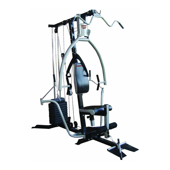
- Page 1 Grizzley 2900 HOME GYM USER MANUAL...
-
Page 2: Table Of Contents
TABLE OF CONTENTS BEFORE YOU BEGIN………………………………………… IMPORTANT SAFETY NOTICES…………………………… HARDWARE PACK…………………………………………… ASSEMBLY INSTRUCTIONS………………………………… PARTS LIST……………………………………………………... -
Page 3: Important Safety Notices
IMPORTANT SAFETY NOTICE PRECAUTIONS This exercise machine is built for optimum safety. However, certain precautions apply whenever you operate a piece of exercise equipment. Be sure to read the entire manual before you assemble or operate your machine. In particular, note the following safety precautions. - Page 4 The warning labels shown here have been placed on the Rear Stabilizer and Upper Frame.
-
Page 5: Hardware Pack
HARDWARE PACK... - Page 6 HARDWARE PACK...
- Page 7 HARDWARE PACK...
-
Page 8: Assembly Instructions
ASSEMBLY INSTRUCTION Tools Required Assembling the Machine: Two Adjustable Wrenches and Allen Wrenches NOTE: It is strongly recommended this machine be assembled by two or more people to avoid possible injury. STEP 1 (See Diagram 1) Attach the butterfly base (M) to the rear base frame (N). Attach the front base frame (L) to the butterfly base (M). - Page 9 DIAGRAM 1...
- Page 10 STEP 2 (See Diagram 2) Attach the upper frame (A) onto the two guide rods (P). Secure it with two M10*70 bolts (37) and two Ф10 washers (44). DO NOT tighten the bolts yet. Place the upper frame (A) onto the vertical frame (D). Secure it with two M10*70 bolts (37), short bracket (Y), Ф10 washers (44), and two M10 lock nut (47).
- Page 11 STEP 3 (See Diagram 3) Attach the iron plate (T) to the front press base (B). Secure it with four M8*16 bolts (33). Attach the front press base (B) to the upper frame (A). Secure it with short joint tube (AI), short double-edged bolt (AC), two Ф12 washers (46), and two M12 lock nuts (48).
- Page 12 DIAGRAM 3...
- Page 13 STEP 4 (See Diagram 4) 1. Attach the seat pad (2) to the seat post (F). Secure it with four M6*16 bolts (32) and four Ф6 big washers (42). 2. Insert the seat post (F) into the opening on the seat support frame (G). Thread the lock knob (9) into the hole on the seat support frame (G) to lock the seat pad (2) at selected height.
- Page 14 STEP 5 (See Diagram 5) Slide the right butterfly (J) onto the right axle on the butterfly base (M). Secure it with one M10*20 (33) and one Ф10 big washer (43). Insert the butterfly handle (I) into the pivot on the right butterfly (J). Secure it with one Ф12 big washer (45) and one M12 lock nut (48) from the bottom.
- Page 15 CABLE LOOP DIAGRAM...
- Page 16 STEP 6 (See Diagram 6 & Upper Cable Loop Diagram) Attach the upper cable (4) to the opening on the front of upper frame (A). Make sure the ball stopper is underneath the frame. Attach a pulley (16) to the cable. Secure the pulley to the opening with one M10*90 (40), two pulley bushings (11), two Ф10 washers (44), and one M10 lock nut (47).
- Page 17 DIAGRAM 6...
- Page 18 Upper Cable Loop Diagram...
- Page 19 STEP 7 (See Diagram 7 & Lower Cable Loop Diagram) Attach the lower cable (6) to the opening on the leg developer (H). Attach a pulley (16) to the opening. Secure it with one M10*70 bolt (37), two leg developer pulley bushings (10), two Ф10 washers (44), and one M10 lock nut (47).
- Page 20 DIAGRAM 7...
- Page 21 Lower Cable Loop Diagram...
- Page 22 STEP 8 (See Diagram 8 & Butterfly Cable Loop Diagram) Attach one end of the butterfly cable (5) to the right butterfly (J). Draw the cable underneath the pulley on the swing pulley bracket (15). Secure it with two pulley covers (50), one M10*50 (35), two Ф10 washers (44), and one M10 lock nut (47).
- Page 23 DIAGRAM 8...
- Page 24 Butterfly Cable Loop Diagram...
- Page 25 STEP 9 (See Diagram 9) Connect the lat bar (X) to the upper cable (4) with a hook (8). Connect the ab curl strap (30) to the mid cable (6) with a hook (8). Connect the shiver bar (S) to the lower cable with two hooks (8) and a chain (7). The ankle strap (31) can be attached to the lower cable with hook (8).
-
Page 26: Parts List
PARTS LIST KEY NO. DESCRIPTION Q’TY UPPER FRAME HOOK FRONT PRESS BASE LOCK KNOB FRONT PRESS LEG DEVELOPER PULLEY BUSHING Φ16*10 VERTICAL FRAME PULLEY BUSHING Φ16*24 BACKREST SUPPORT FRAME BUSHING Φ38*Φ19 SEAT POST BUSHING Φ28*Φ16 SEAT SUPPORT FRAME WEIGHT PLATE SELECTOR PIN LEG DEVELOPER SWING PULLEY BRACKET BUTTERFLY HANDLE...
Need help?
Do you have a question about the Grizzley 2900 and is the answer not in the manual?
Questions and answers