
Related Manuals for KLS Martin IDP 101 S air plus


Summary of Contents for KLS Martin IDP 101 S air plus
- Page 1 ® Suspension Arm Systems Independant IDP 101 S air plus English Mounting Instructions 90-061-72-10 Revision 1 Date of Release: 2016-06...
- Page 2 Symbol Explanation Safety alert symbol CAUTION Indicates a situation which, if not avoided, could result in minor or moderate injury. WARNING Indicates a situation which, if not avoided, could result in death or serious injury. DANGER Indicates a situation which, if not avoided, will result in death or serious injury.
- Page 3 Danger of crushing Warns against trapping limbs during assembly/disassembly work. Danger of collisions Warns against collisions with components of the suspension arm system during assembly/disassembly work. Non-ionizing electromagnetic radiation Cautions against disturbance of medical devices and electronic implants by the high-frequency electromagnetic radiation emitted by cellular and radio transmitters.
-
Page 4: Table Of Contents
Overview and Scope of Delivery for IDP101 S air plus, Single Arm ......8 1.2.2 Overview and Scope of Delivery IDP 101 S air plus, Dual Arm ......11 1.2.3 Overview and Scope of Delivery of Optional Equipment ........14 1.2.4... - Page 5 Commissioning ................30 Initial Commissioning and Handover ............30 Load Data ................. 31 Load Data for IDP 101 S air plus ............31 Load Data for Suspension Arm Combinations .......... 32 Mounting ................... 33 Mounting the Threaded Bolts on the Interface Plate ......... 33 7.1.1...
- Page 6 Technical Specification ..............98 Dimensional Drawings ................. 98 9.1.1 Spring Arm, IDP 101 S air plus, Single Arm, with M6 Service Head ....... 98 9.1.2 Spring Arm, IDP 101 S air plus, Dual Arm, with M6 Service Head ......99 Technical Data ..................
-
Page 7: Terms & Acronyms
We are the manufacturer of this product: Gebrüder Martin GmbH & Co. KG A company of the KLS Martin Group KLS Martin Platz 1 · D-78532 Tuttlingen · Germany Postfach 60 · D-78501 Tuttlingen · Germany Tel. +49 7461 706-0 · Fax +49 7461 706-193 info@klsmartin.com ·... -
Page 8: Scope Of Delivery
® Suspension Arm Systems Independant Scope of Delivery 1.2.1 Overview and Scope of Delivery for IDP101 S air plus, Single Arm Fig. 1-1: Overview of IDP 101 S air plus, single arm Overview – Interface plate (Single/Duo) already installed –... - Page 9 Mounting Instructions ® Suspension Arm Systems Independant Scope of delivery The scope of delivery may vary depending on the order. Canopy (Single/Duo) (flat/high) (depending on version) 1 Single canopy Ø 600 mm x 150 mm, 1 canopy cap 110 mm height −...
- Page 10 Mounting Instructions ® Suspension Arm Systems Independant Longer ceiling tube for spring arm 1 ceiling tube (customized length) − 1 earthing cable 4 mm² − Included components 1 socket wrench extension (only for ceiling tube lengths 500 and 700 mm) −...
-
Page 11: Overview And Scope Of Delivery Idp 101 S Air Plus, Dual Arm
Mounting Instructions ® Suspension Arm Systems Independant 1.2.2 Overview and Scope of Delivery IDP 101 S air plus, Dual Arm Fig. 1-2: Overview IDP 101 S air plus, dual arm Overview – Interface plate (Single/Duo) already installed – Intermediate ceiling... - Page 12 Mounting Instructions ® Suspension Arm Systems Independant Scope of delivery The scope of delivery may vary depending on the order. Canopy (Single/Duo) (flat/high) (depending on version) 1 Single canopy Ø 600 mm x 150 mm, 1 canopy cap 110 mm height −...
- Page 13 Mounting Instructions ® Suspension Arm Systems Independant Longer ceiling tube 1 ceiling tube (customized length) − 1 earthing cable 4 mm² − Included components 1 socket wrench extension (only for ceiling tube lengths 500 and 700 mm) − Fastening elements for additional ceiling tube 8 Allen cylinder screws M10 x 25 mm (8.8) DIN EN ISO 4762 −...
-
Page 14: Overview And Scope Of Delivery Of Optional Equipment
Mounting Instructions ® Suspension Arm Systems Independant 1.2.3 Overview and Scope of Delivery of Optional Equipment Fig. 1-3: Overview of optional equipment On delivery of the system from the factory, the listed options are already installed. Indirect extension arm light (extension arm lengths 1,000 and 1,200 mm) 1 extension arm light (length 600 mm, input voltage 12 VDC) −... -
Page 15: Intended Purpose
® Suspension Arm Systems Independant Intended Purpose The suspension arm system IDP 101 S air plus is individually equipped. Depending on • version and fitted equipment, it can be used for the following: — carrying and positioning of medical end devices in the operating room, in intensive care, and in other medical environments. -
Page 16: Improper Use
Mounting Instructions ® Suspension Arm Systems Independant 1.3.1 Improper Use The suspension arm system and its components must not be loaded beyond their maximum load-bearing capacity, see section 9.2 “Technical Data”, page 100. 1.3.2 Contraindications The suspension arm system must not be used in the proximity of strong magnetic fields. No applied parts of type BF or CF in accordance with IEC 60601-1 may be directly connected to the suspension arm system. -
Page 17: Hotline
Mounting Instructions ® Suspension Arm Systems Independant Hotline Should you have any questions on how to handle the product or use it for clinical • applications, please do not hesitate to contact the Product Management: Tel: +49 7461 706-321 Fax: +49 7461 706-190 Should you have any technical questions or questions concerning maintenance contracts or •... -
Page 18: Notices Concerning This Document
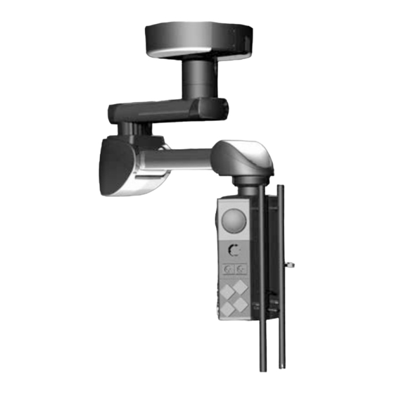
Validity of this Document ® This document applies to Independant IDP 101 S air plus, which is used as suspension arm system for the M6 service head. This document is valid only in conjunction with: Instructions for use of the M6 service head •... - Page 19 Mounting Instructions ® Suspension Arm Systems Independant Part 02: • Suspension arm system Fig. 2-2: Suspension arm system Part 03: • M6 service head Fig. 2-3: M6 service head Part 04: • Approved equipment for the M6 service head Fig. 2-4: Approved optional equipment Revision 1...
-
Page 20: Symbols Used In This Document
Mounting Instructions ® Suspension Arm Systems Independant Symbols Used in this Document Throughout this document, important information (such as general or safety-related notices) is marked with the following symbols and signal words: DANGER Life hazard or serious injury! Indicates a situation which, if not avoided, will result in death or serious injury! WARNING Life hazard or serious injury! Indicates a situation which, if not avoided, could result in death or serious injury! -
Page 21: Instructions For Safe Installation
Information on Device Identification These instructions for use are intended solely for devices identified on the rating plate by the following data: Type designation: Suspension arm system IDP 101 S air plus • Required Installation Equipment Lifting device, e.g. RIECK “ALP Montagelift LMC500” or forklift, with a permitted loading •... -
Page 22: Assembly Process
Mounting Instructions ® Suspension Arm Systems Independant 3.3.3 Assembly Process The unit must be connected to the power source by a qualified electrician only while the • power supply has switched off. The unit must be installed according to the steps described in these Mounting Instructions. •... -
Page 23: Notes For Operators
Mounting Instructions ® Suspension Arm Systems Independant Notes for Operators The device is manufactured according to the current state of technology and is safe to • operate. Potential dangers may still be present, however, when using this device. This applies in particular if the device is operated by personnel without the necessary qualifications, or if it is used improperly and not in accordance with its intended purpose. -
Page 24: Patient Environment
Mounting Instructions ® Suspension Arm Systems Independant Patient Environment Any electrical medical devices with accessible metal parts that are attached to the support arm system and located within the patient environment must be equipped with 2 means of patient protection (MOPP) according to IEC 60601-1. -
Page 25: Safety Notes
Mounting Instructions ® Suspension Arm Systems Independant Safety Notes Data on the Rating Plate Fig. 4-1: Rating plate, example: IDP 101 S Single The certification signs are located on top of the extension arm. Extension Arm • The rating plate displays the length of the extension arm. Serial number (SN) •... -
Page 26: The Most Important Safety Information At A Glance
Mounting Instructions ® Suspension Arm Systems Independant The Most Important Safety Information at a Glance Please also comply with the safety instructions in the following sections. 4.2.1 Operation WARNING Risk of injury from collapse of the suspension arm system if the maximum load- bearing capacity is exceeded! Exceeding the maximum permissible load-bearing capacity can cause the suspension arm system or its components to loosen from the anchorage and fall down:... -
Page 27: Assembly/Disassembly
Mounting Instructions ® Suspension Arm Systems Independant 4.2.2 Assembly/Disassembly WARNING Danger of injury from electric shock! Power supply lines run in the suspension arm system and the M6 service head. Touching live parts can cause life-threatening electric shock. In order to avoid the risk of electric shock, the suspension arm system may be connected •... -
Page 28: Maintenance Work
Mounting Instructions ® Suspension Arm Systems Independant 4.2.3 Maintenance Work WARNING Danger of injury from electric shock! Power supply lines run in the suspension arm system and the M6 service head. Touching live parts can cause life-threatening electric shock. In order to avoid the risk of electric shock, the suspension arm system may be connected •... -
Page 29: Safe Handling Of Oxygen
Mounting Instructions ® Suspension Arm Systems Independant 4.2.4 Safe Handling of Oxygen DANGER Danger to life from oxygen explosion! Oxygen reacts explosively with oils, greases and lubricants. Danger of explosion due to highly compressed oxygen: Keep the oxygen and gas modules free of substances that contain oil, grease or •... -
Page 30: Commissioning
Mounting Instructions ® Suspension Arm Systems Independant Commissioning Initial Commissioning and Handover Initial commissioning The entire suspension arm system and the M6 service head have to be correctly commissioned after installation has been completed. Functional check The suspension arm system and the M6 service head must not be used on the patient before the operator or a person authorized by the operator has performed a function check at the operating site, and the persons assigned by the operator have been instructed. -
Page 31: Load Data
Maximum Spring arm length, Load bearing Weight Force of the Bending single arm [mm] capacity [kg] Force [N] Ceiling Mount [N] Moment[Nm] 1,015 2,578 1,300 1,900 Table 6-2: Load data for IDP 101 S air plus, single arm Revision 1... -
Page 32: Load Data For Suspension Arm Combinations
Duo versions can be added. Example IDP 101 S air plus (spring arm 1,015 mm) on ceiling mount combined with IDP 501 XL (extension arm 1,200/1,000 mm): Sum of weight forces: 2,578 N + 3,599 N + 1,300 N = 8,478 N •... -
Page 33: Mounting
Mounting Instructions ® Suspension Arm Systems Independant Mounting Mounting the Threaded Bolts on the Interface Plate 7.1.1 Mounting Conditions: Interface Plate on the Raw Ceiling without Intermediate Ceiling Fig. 7-1: Shortening and mounting the threaded bolts for the interface plates on the raw ceiling (Single/Duo) Shortening the threaded bolts If Single/Duo interface plates... - Page 34 Mounting Instructions ® Suspension Arm Systems Independant Mounting the threaded bolts Attach 1 hexagonal nut M16 on each of the 6/12 threaded bolts and use 1 spring • washer for each. WARNING Danger of injury due to the suspension arm system falling! If the threaded bolts are not fully screwed in, they can tear out of the interface plate and cause the suspension arm system to fall:...
- Page 35 Mounting Instructions ® Suspension Arm Systems Independant Mounting the upper insulation on the threaded bolts Fig. 7-2: Mounting the upper insulation on the threaded bolts (Single/Duo) The 6 (Single version) or 12 (Duo version) hexagonal nuts M16 must be mounted at a precise distance to the threaded bolts M16 Screw on 1 hexagonal nut to the threaded bolt...
-
Page 36: Mounting Conditions: Interface Plate On The Raw Ceiling With Intermediate Ceiling
Mounting Instructions ® Suspension Arm Systems Independant 7.1.2 Mounting Conditions: Interface Plate on the Raw Ceiling with Intermediate Ceiling Fig. 7-3: Shortening the threaded bolts for the interface plate on the raw ceiling (Single/Duo) Shortening the threaded bolts If Single/Duo interface plates are mounted on a raw ceiling with intermediate ceiling 6 (Single version) or 12 (Duo version) M16 x 330 mm threaded bolts will have to be... - Page 37 Mounting Instructions ® Suspension Arm Systems Independant If the Single/Duo canopy is 150 mm high, shorten the 6/12 threaded bolts Determine the length LG of the threaded bolts • LG = H + 135 mm (min. 205 mm/max. 245 mm) (in case of doubt, contact Gebrüder Martin).
- Page 38 Mounting Instructions ® Suspension Arm Systems Independant WARNING Danger of injury due to the suspension arm system falling! If the threaded bolts are not fully screwed in, they can tear out of the interface plate and cause the suspension arm system to fall: Fully screw in all shortened threaded bolts into the interface plate up to the end...
- Page 39 Mounting Instructions ® Suspension Arm Systems Independant Mounting the upper insulation on the threaded bolts Fig. 7-5: Mounting the upper insulation on the threaded bolts (Single/Duo) Screw on 1 hexagonal nut M16 to the threaded bolts , for each threaded bolt M16 •...
-
Page 40: Mounting Conditions: Interface Plate On The Intermediate Ceiling Mount
Mounting Instructions ® Suspension Arm Systems Independant 7.1.3 Mounting Conditions: Interface Plate on the Intermediate Ceiling Mount Fig. 7-6: Mounting the threaded bolts (Single/Duo) Mounting the threaded bolts The 6 (Single version) or 12 (Duo version) threaded bolts M16 x 330 mm must protrude from the interface plate by a precise distance. - Page 41 Mounting Instructions ® Suspension Arm Systems Independant WARNING Danger of injury due to the suspension arm system falling! To ensure proper stability, the threaded bolts must not exceed a length of 330 mm. • Ensure that the maximum length is not exceeded. Attach 1 hexagonal nut M16 on each of the 6/12 threaded bolts and use 1 spring...
- Page 42 Mounting Instructions ® Suspension Arm Systems Independant Mounting the upper insulation on the threaded bolts Fig. 7-7: Mounting the upper insulation on the threaded bolts (Single/Duo) The 6 (Single version) or 12 (Duo version) hexagonal nuts M16 must be mounted at a precise distance to the threaded bolts M16 x 330 mm Screw on 1 hexagonal nut to the threaded bolt...
-
Page 43: Pre-Assembly: Mounting The Longer Ceiling Tube On The Extension Arm
Mounting Instructions ® Suspension Arm Systems Independant Pre-assembly: Mounting the Longer Ceiling Tube on the Extension Arm 7.2.1 Overview of the Components in this Section The ceiling tube shown in the illustration is mounted to the spring arm or the extension arm with spring arm For reasons of simplification, the illustration shows the spring arm... -
Page 44: Mounting The Longer Ceiling Tube
Mounting Instructions ® Suspension Arm Systems Independant 7.2.2 Mounting the longer Ceiling Tube Mounting the ceiling tube As an example, the illustration shows the spring or extension arm with spring arm without pre-installed cables. Place the ceiling tube on the spring •... - Page 45 Mounting Instructions ® Suspension Arm Systems Independant Check that the spring arm or the extension arm with spring arm is securely in • place: The ceiling tube must sit flush on the spring arm or extension arm with spring • The 7 cylinder screws must be installed with retaining washers •...
- Page 46 Mounting Instructions ® Suspension Arm Systems Independant Mounting the tension relief on the ceiling tube As an example, the illustration shows the spring or extension arm with spring arm without pre-installed cables. Insert 1 Allen cylinder screw M10 x 25 mm •...
- Page 47 Mounting Instructions ® Suspension Arm Systems Independant WARNING Danger of injury due to the suspension arm system falling! Insufficiently tightened fastening elements can cause the suspension arm system to fall: Tighten all cylinder screws with a torque of 40 Nm. •...
-
Page 48: Mounting The Ceiling Tube On The Threaded Bolts Of The Interface Plate
Mounting Instructions ® Suspension Arm Systems Independant Mounting the Ceiling Tube on the Threaded Bolts of the Interface Plate 7.3.1 Overview of the Components in this Section The spring arm or extension arm with spring is mounted to the threaded bolts of the interface plate For reasons of simplification, the illustration shows the spring arm... -
Page 49: Mounting The Ceiling Tube
Mounting Instructions ® Suspension Arm Systems Independant 7.3.2 Mounting the Ceiling Tube For reasons of simplification, the illustration only shows the flange with ceiling tube that is mounted to the threaded bolts. Additional components pre-mounted on the flange , e.g. spring arm, extension arm or cables, are not illustrated. - Page 50 Mounting Instructions ® Suspension Arm Systems Independant WARNING Danger of injury from falling parts! During the installation, parts may fall. During the installation, no-one must stand beneath the components of the suspension arm system. WARNING Danger of injury from falling parts! During the installation, no-one must stand beneath the components of the suspension arm system.
-
Page 51: Adjusting The Spring Arm/Extension Arm On The Single Interface Plate
Mounting Instructions ® Suspension Arm Systems Independant 7.3.3 Adjusting the Spring Arm/Extension Arm on the Single Interface Plate For reasons of simplification, the illustration only shows the flange with ceiling tube that is mounted to the threaded bolts. Additional components pre-mounted on the flange , e.g. - Page 52 Mounting Instructions ® Suspension Arm Systems Independant Choose one of the 6 hexagonal nuts • reference point. Screw on the 6 hexagonal nuts under the • flange in a crosswise sequence to the flange and tighten with 100 Nm. Remove the transport protection (tape) •...
-
Page 53: Adjusting The Spring Arm/Extension Arm On The Duo Interface Plate
Mounting Instructions ® Suspension Arm Systems Independant 7.3.4 Adjusting the Spring Arm/Extension Arm on the Duo Interface Plate For reasons of simplification, the illustration only shows the flange with ceiling tube that is mounted to the threaded bolts. Additional components pre-mounted on the flange , e.g. - Page 54 Mounting Instructions ® Suspension Arm Systems Independant Choose one of the 6 hexagonal nuts • reference point. Screw on the 6 hexagonal nuts under the • flange in a crosswise sequence to the flange and tighten with 100 Nm. Repeat for the second flange. •...
-
Page 55: Mounting The Console Tube On The Spring Arm
Mounting Instructions ® Suspension Arm Systems Independant Ensure that all hexagonal nuts are safely in place: The 24 hexagonal nuts must butt against the flange • The 24 plastic insulating washers above and below the flange must sit in the •... -
Page 56: Mounting The Console Tube On The Spring Arm
Mounting Instructions ® Suspension Arm Systems Independant 7.4.2 Mounting the Console Tube on the Spring Arm Position the console tube under the • spring arm or extension arm with spring in a way that the stop in the console tube points away from the side of the spring arm and the fastening holes are aligned. -
Page 57: Mounting Optional Equipment
Mounting Instructions ® Suspension Arm Systems Independant Mounting Optional Equipment On delivery of the system ex works, the listed options are already pre-installed. 7.5.1 Mounting the Extension Arm Light (only for Retrofitting) The indirect extension arm light (possible for extension arms from 800 mm length) is mounted on top of the extension arm. -
Page 58: Installing The Cables
Mounting Instructions ® Suspension Arm Systems Independant Installing the Cables 7.6.1 Safety Notes WARNING Risk of death by electrocution! Power supply lines can be installed in the suspension arm system. Touching live parts can cause life-threatening electric shock. Motor-controlled, movable components of the unit can cause injuries when activated accidentally. -
Page 59: Connecting The Cables On The Extension Arm With Spring Arm, Dual Arm, To The M6 Service Head
Mounting Instructions ® Suspension Arm Systems Independant WARNUNG Danger of injury due to leaking compressed air pipes of the pneumatic brakes! Check the brake pipes, air supply ducts and brake valves for contamination and clean • them if required before mounting them. Cut off the brake pipes, Ø... -
Page 60: Laying And Connecting The Pneumatic Brake Pipes
Mounting Instructions ® Suspension Arm Systems Independant Laying the power cable Lay the power cable (laid in a spiral coiled tube if required) through the spring arm • above the swivel axis (swivel joint ) and lead it out of the mounting opening in the bearing block of the spring arm. - Page 61 Mounting Instructions ® Suspension Arm Systems Independant The pneumatic brake pipes are pre-assembled in the suspension arm system and plugged onto the brake connecting points . The pneumatic brake pipes are possibly laid in a spiral tube. Installing and dismantling brake pipes The pneumatic supply pipe must be pressureless: To install the brake pipes, push them into the brake connecting point.
-
Page 62: Connecting The Optional Extension Arm Lighting
Mounting Instructions ® Suspension Arm Systems Independant 7.6.4 Connecting the Optional Extension Arm Lighting Observe the safety notes, see section 7.6.1 “Safety Notes”, page 58. • Fig. 7-23: Connecting the optional extension arm lighting Length From Designation Note [mm] Extension arm integrated into the Cable lighting... -
Page 63: Connecting The Earthing Cables On The Extension Arm With Spring Arm, Dual Arm, To The M6 Service Head
Mounting Instructions ® Suspension Arm Systems Independant 7.6.5 Connecting the Earthing Cables on the Extension Arm with Spring Arm, Dual Arm, to the M6 Service Head Observe the safety notes, see section 7.6.1 “Safety Notes”, page 58. • Check protective resistor, see section 10 “Inspection Plan”, page 103. •... -
Page 64: Feeding The Supply Cables Through The Extension Arm With Spring Arm, Dual Arm, To The M6 Service Head
Mounting Instructions ® Suspension Arm Systems Independant 7.6.6 Feeding the Supply Cables Through the Extension Arm with Spring Arm, Dual Arm, to the M6 Service Head Observe the safety notes, see section 7.6.1 “Safety Notes”, page 58. • Fig. 7-25: Feeding the supply cables through the extension arm with spring arm, dual arm, to the M6 service head The power cables, pneumatic pipes, earthing and control cables, as well as the gas hoses are... -
Page 65: Connecting The Cables On The Spring Arm, Single Arm, To The M6 Service Head
Mounting Instructions ® Suspension Arm Systems Independant 7.6.7 Connecting the Cables on the Spring Arm, Single Arm, to the M6 Service Head Observe the safety notes, see section 7.6.1 “Safety Notes”, page 58. • Fig. 7-26: Connecting the cables on the spring arm, single arm, to the M6 service head The power cables, pneumatic pipes, earthing and control cables, as well as the gas hoses are pre-installed in the M6 Service Head and must be routed through the pendant system. -
Page 66: Laying And Connecting The Pneumatic Brake Pipes
Mounting Instructions ® Suspension Arm Systems Independant 7.6.8 Laying and Connecting the Pneumatic Brake Pipes Observe the safety notes, see section 7.6.1 “Safety Notes”, page 58. • Fig. 7-27: Laying and connecting the pneumatic brake pipes The pneumatic brake pipes are pre-assembled in the suspension arm system and plugged onto the brake connecting point . - Page 67 Mounting Instructions ® Suspension Arm Systems Independant Installing and dismantling brake pipes The pneumatic supply pipe must be pressureless: To install the brake pipes, push them into the brake connecting point. If the brake pipe is • correctly positioned, it can no longer be withdrawn from the brake connecting point. To disengage the brake pipes on the plug connector push in the unlocking •...
-
Page 68: Connecting The Earthing Cables On The Spring Arm, Single Arm, To The M6 Service Head
Mounting Instructions ® Suspension Arm Systems Independant 7.6.9 Connecting the Earthing Cables on the Spring Arm, Single Arm, to the M6 Service Head Observe the safety notes, see section 7.6.1 “Safety Notes”, page 58. • Check protective resistor, see section 10 “Inspection Plan”, page 103. •... -
Page 69: Feeding The Supply Cables Through The Spring Arm, Single Arm, To The M6 Service Head
Mounting Instructions ® Suspension Arm Systems Independant 7.6.10 Feeding the Supply Cables Through the Spring Arm, Single Arm, to the M6 Service Head Observe the safety notes, see section 7.6.1 “Safety Notes”, page 58. • Fig. 7-29: Feeding the supply cables through the spring arm, single arm, to the M6 Service Head The power cables, pneumatic pipes, earthing and control cables, as well as the gas hoses are pre-installed in the M6 Service Head and must be laid through the pendant system. -
Page 70: Connecting The Supply Cables
Mounting Instructions ® Suspension Arm Systems Independant Connecting the Supply Cables 7.7.1 Safety Notes WARNING Risk of death if unqualified staff is used (electrical power supply)! The electrical connection of the suspension arm system and the M6 service head must only be done by a qualified electrician: Observe the safety notes in the Mounting Instructions, Part 1: Ceiling Mount, section •... -
Page 71: Installing The Cables For The Gas Supply And Exhaust Air
Mounting Instructions ® Suspension Arm Systems Independant WARNING Risk of death by electrocution due to insulation defect! An insulation defect can electrify the suspension arm system or the M6 service head: Always earth the suspension arm system and the M6 service head. •... - Page 72 Mounting Instructions ® Suspension Arm Systems Independant The illustration shows an example for the gas supply. Ensure the correct assignment of the cables to the corresponding supply connections. Check gas supply cables for contamination • and clean with oil-free air if necessary. Attach a hose clamp to the gas supply •...
-
Page 73: Connecting The Earthing Cables
Mounting Instructions ® Suspension Arm Systems Independant 7.7.3 Connecting the Earthing Cables Fig. 7-31: Connecting the earthing cables (Single and Single/Duo) For reasons of simplification, the illustrations show the interface plate without extension arm or cables. Observe the safety notices, see section 7.7.1 “Safety Notes”, page 70. •... -
Page 74: Checking The Supply Cables
Mounting Instructions ® Suspension Arm Systems Independant Feed all power cables through the tension relief and connect them to the terminal • unit according to the wiring diagram provided by the customer. Ensure that the power cables are safely in place in the tension relief All power cables must sit securely in the tension relief •... -
Page 75: Mounting The Canopy, Cover Caps And Claddings
Mounting Instructions ® Suspension Arm Systems Independant Mounting the Canopy, Cover Caps and Claddings 7.9.1 Mounting the Single/Duo Canopy Preparing to mount the canopy For reasons of simplification, the illustration shows the interface plate without cables and extension arm or spring arm. Screw hexagonal nuts M10 on the •... - Page 76 Mounting Instructions ® Suspension Arm Systems Independant Mounting the canopy halves For reasons of simplification, the illustration shows the interface plate without cables and extension arm or spring arm. Attach profile strip (not illustrated) to the • first canopy half (if desired, the canopy can be sealed with silicone sealant).
-
Page 77: Mounting The Single Canopy
Mounting Instructions ® Suspension Arm Systems Independant 7.9.2 Mounting the Single Canopy Preparing to mount the canopy For reasons of simplification, the illustration shows the interface plate without cables and extension arm or spring arm. Screw hexagonal nuts M10 on the •... - Page 78 Mounting Instructions ® Suspension Arm Systems Independant Mounting the canopy halves For reasons of simplification, the illustration shows the interface plate without cables and extension arm or spring arm. Attach profile strip (not illustrated) to the • first canopy half (if desired, the canopy can be sealed with silicone sealant).
-
Page 79: Installing/Uninstalling The Cover Caps On The Extension Arm
Mounting Instructions ® Suspension Arm Systems Independant 7.9.3 Installing/Uninstalling the Cover Caps on the Extension Arm Installing the cover caps For reasons of simplification, the illustration shows the extension arm with spring arm without cables. The detailed illustration shows the cover cap as sectional view. - Page 80 Mounting Instructions ® Suspension Arm Systems Independant Uninstalling the cover caps For reasons of simplification, the illustration shows the extension arm with spring arm without cables. The detailed illustration shows the cover cap as sectional view. To uninstall the cover cap, slide a flat, •...
-
Page 81: Mounting The Plates On The Spring Arm
Mounting Instructions ® Suspension Arm Systems Independant 7.9.4 Mounting the Plates on the Spring Arm The illustration shows the spring arm . The mounting process for the extension arm with spring arm is identical. For reasons of simplification, the illustration shows the spring arm without cables or main board. -
Page 82: Mounting The Side Cladding On The Spring Arm
Mounting Instructions ® Suspension Arm Systems Independant ) around Mounting the rear plates Place the 2 rear plate halves (spring side, recognizable by the two recesses • the spring arm. Please note: To latch the two plate halves place them inside each other and slide together in the •... -
Page 83: Mounting The Lower Rear Cover Panels On The Spring Arm
Mounting Instructions ® Suspension Arm Systems Independant 7.9.6 Mounting the Lower Rear Cover Panels on the Spring Arm The illustration shows the spring arm . The mounting process for the extension arm with spring arm is identical. For reasons of simplification, the illustration shows the spring arm without cables or main board. -
Page 84: Mounting The Front Side Claddings On The Spring Arm
Mounting Instructions ® Suspension Arm Systems Independant 7.9.7 Mounting the Front Side Claddings on the Spring Arm The illustration shows the spring arm . The mounting process for the extension arm with spring arm is identical. For reasons of simplification, the illustration shows the spring arm without cables. -
Page 85: Mounting The Upper Front Cover Panel On The Spring Arm
Mounting Instructions ® Suspension Arm Systems Independant 7.9.8 Mounting the Upper Front Cover Panel on the Spring Arm The illustration shows the spring arm . The mounting process for the extension arm with spring arm is identical. For reasons of simplification, the illustration shows the spring arm without cables. -
Page 86: Adjustment Work
Mounting Instructions ® Suspension Arm Systems Independant Adjustment Work Safety Notice for Adjustment Work WARNING Risk of death by electrocution! Power supply lines are installed in the suspension arm system. Touching live parts can cause life-threatening electric shock. Disconnect the unit from the mains before beginning any adjustment work: For all types of installation or adjustment work, turn off the suspension arm system and •... -
Page 87: Selecting The Load-Bearing Capacity On The Spring Arm
Mounting Instructions ® Suspension Arm Systems Independant Tools to be used Use a suitable flat-bade screwdriver. Increasing the braking force Insert the flat-blade screwdriver into the • brake screw and turn it to the right (clockwise). Reducing the braking force Insert the flat-blade screwdriver into the •... - Page 88 Mounting Instructions ® Suspension Arm Systems Independant Opening the lower cover panel on the rear The illustration shows the extension arm and spring arm, for simplification without installed cables. The adjustment is identical for all versions. Observe the safety notice, see section 8.1 •...
- Page 89 Mounting Instructions ® Suspension Arm Systems Independant Setting the load-bearing capacity and closing the lower cover on the rear Tools to be used Hexagon spanner SW 10 or • Ring spanner SW 24 • Setting the Load-Bearing Capacity • Unscrew the Allen cylinder screw M8 x 16 mm DIN 7984.
- Page 90 Mounting Instructions ® Suspension Arm Systems Independant NOTICE Change of the load-bearing capacity due to incorrect torque If the Allen cylinder screw is not tightened properly, the load-bearing capacity may slowly change during operation over time. The spring arm will then fail to remain in the set position. Tighten the cylinder screw with a torque of 12 Nm.
-
Page 91: Adjusting The Vertical Lift On The Spring Arm
Mounting Instructions ® Suspension Arm Systems Independant Adjusting the Vertical Lift on the Spring Arm When replacing an end device (e.g. TFT monitor or medical device), the spring arm must be adjusted in the horizontal position (0°). Opening the upper casing on the front Observe the safety notice, see section 8.1 •... - Page 92 Mounting Instructions ® Suspension Arm Systems Independant NOTICE Change of the vertical lift due to incorrect torque If the hexagon nut is not tightened properly, the vertical lift may slowly change during operation over time. The spring arm can then collide with the ceiling or another suspension arm system arm system.
-
Page 93: Correcting The Vertical Alignment Of The M6 Service Head
Mounting Instructions ® Suspension Arm Systems Independant Correcting the Vertical Alignment of the M6 Service Head After the installation of an end device, the shelf of the M6 service head may not perfectly vertical due to the weight of the end device. Opening the lower casing on the rear Observe the safety notice, see section 8.1 •... -
Page 94: Swivel Stop On The Extension Arm And Spring Arm
Mounting Instructions ® Suspension Arm Systems Independant NOTICE Changes to the vertical alignment due to incorrect tightening torque If the setscrew is not tightened properly, the vertical alignment may slowly change during operation over time. The M6 Service Head will then fail to remain in the set position. Tighten the setscrew with a torque of 2 Nm. -
Page 95: Installing The Swivel Stop
Mounting Instructions ® Suspension Arm Systems Independant 8.6.1 Installing the Swivel Stop Observe the safety notice, see section 8.1 • “Safety Notice for Adjustment Work”, page 86. Unscrew the setscrew from the • threaded hole Turn the extension arm or spring arm to the •... - Page 96 Mounting Instructions ® Suspension Arm Systems Independant WARNING Risk of death by electrocution! Insufficiently tightened fastening elements can lead to failure of the swivel stop. Moreover, supply cables could loosen: Tighten the M16 setscrew to 40 Nm. • Check that the swivel stop is working properly: The range of rotation of the extension arm or spring arm must be limited to less than •...
-
Page 97: Removing The Swivel Stop
Mounting Instructions ® Suspension Arm Systems Independant 8.6.2 Removing the Swivel Stop Observe the safety notice, see section 8.1 • “Safety Notice for Adjustment Work”, page 86. Unscrew the setscrew M16 DIN EN • ISO 4028 from the threaded hole Rotate the extension arm or spring arm •... -
Page 98: Technical Specification
The round canopy can be installed only with the round interface panel. The square 700 mm × 700 mm canopy can be installed solely with the square interface panel. 9.1.1 Spring Arm, IDP 101 S air plus, Single Arm, with M6 Service Head Revision 1... -
Page 99: Spring Arm, Idp 101 S Air Plus, Dual Arm, With M6 Service Head
Mounting Instructions ® Suspension Arm Systems Independant 9.1.2 Spring Arm, IDP 101 S air plus, Dual Arm, with M6 Service Head Revision 1... -
Page 100: Technical Data
9.2.1 Dead Weight Designation Dead weight Spring arm, length 1,015 mm 83 kg IDP 101 S air plus with spring arm Extension arm 600 mm 102 kg Extension arm 800 mm 105 kg Extension arm 1,000 mm 108 kg... -
Page 101: General Technical Data
Mounting Instructions ® Suspension Arm Systems Independant 9.2.4 General Technical Data Designation All suspension arm systems Operating mode suitable for continuous operation The rating plate is located on the upper extension Rating plate arm, see section 4.1 “Data on the Rating Plate”, page 25. -
Page 102: Permissible Adaptions
Mounting Instructions ® Suspension Arm Systems Independant Permissible Adaptions The following products are permitted as adaptions to the suspension arm system: M6 service head and approved end devices in accordance with the current instruction • manual for the M6 service head Optional accessories •... -
Page 103: Inspection Plan
Mounting Instructions ® Suspension Arm Systems Independant Inspection Plan M6 service head with IDP ® CEMOR with IDP Supplier: Installation date: Serial no.: Operator serial number: Device location: Notice This inspection plan is valid only in connection with the Mounting Instructions and the •... - Page 104 Mounting Instructions ® Suspension Arm Systems Independant Not OK Gas modules (if provided) are firmly installed and functional** • • Have gas modules and supply lines (if provided) inspected by an authorized entity for gas type and gas density** The installed hoses and supply lines must be inspected annually for visible •...
-
Page 105: Ecological Information
Mounting Instructions ® Suspension Arm Systems Independant Ecological Information 11.1 Packaging Gebrüder Martin will, as a matter of course, take back the full packaging if so desired, to recycle as many parts of the packaging as possible. If you do not wish to make use of this offer, you can dispose of the packaging with the normal paper or domestic garbage. - Page 106 Gebrüder Martin GmbH & Co. KG A company of the KLS Martin Group KLS Martin Platz 1 · 78532 Tuttlingen · Germany Postfach 60 · 78501 Tuttlingen · Germany Tel. +49 7461 706-0 · Fax +49 7461 706-193 info@klsmartin.com · www.klsmartin.com Date of Release: 2016-06 ·...
Need help?
Do you have a question about the IDP 101 S air plus and is the answer not in the manual?
Questions and answers