Sign In
Upload
Manuals
Brands
KLS Martin Manuals
Medical Equipment
IDP 101 S air plus
KLS Martin IDP 101 S air plus Manuals
Manuals and User Guides for KLS Martin IDP 101 S air plus. We have
1
KLS Martin IDP 101 S air plus manual available for free PDF download: Mounting Instructions
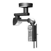
KLS Martin IDP 101 S air plus Mounting Instructions (106 pages)
Suspension Arm Systems Independant
Brand:
KLS Martin
| Category:
Medical Equipment
| Size: 3 MB
Table of Contents
Table of Contents
4
Terms & Acronyms
7
Product Liability and Warranty
7
General Information
7
Scope of Delivery
8
Overview and Scope of Delivery for IDP101 S Air Plus, Single Arm
8
Overview and Scope of Delivery IDP 101 S Air Plus, Dual Arm
11
Overview and Scope of Delivery of Optional Equipment
14
Additional Optional Equipment
14
Intended Purpose
15
Improper Use
16
Contraindications
16
Warranty
16
User's Inspection
16
Hotline
17
Notices Concerning this Document
18
Validity of this Document
18
Applicable Mounting Instructions
18
Symbols Used in this Document
20
Instructions for Safe Installation
21
Information on Device Identification
21
Required Installation Equipment
21
Requirements
21
Requirements for the Qualifications of the Service Technician
21
Requirements before Installation
21
Assembly Process
22
Unauthorized Modifications or Adjustments
22
Qualified Medical Staff
22
Notes for Operators
23
Standards and Guidelines
23
Combination with Products by Other Manufacturers
23
Patient Environment
24
Safety Notes
25
Data on the Rating Plate
25
The most Important Safety Information at a Glance
26
Operation
26
Assembly/Disassembly
27
Maintenance Work
28
Safe Handling of Oxygen
29
Commissioning
30
Initial Commissioning and Handover
30
Load Data
31
Load Data for IDP 101 S Air Plus
31
Load Data for Suspension Arm Combinations
32
Mounting
33
Mounting the Threaded Bolts on the Interface Plate
33
Mounting Conditions: Interface Plate on the Raw Ceiling Without Intermediate Ceiling
33
Mounting Conditions: Interface Plate on the Raw Ceiling with Intermediate Ceiling
36
Mounting Conditions: Interface Plate on the Intermediate Ceiling Mount
40
Pre-Assembly: Mounting the Longer Ceiling Tube on the Extension Arm
43
Overview of the Components in this Section
43
Mounting the Longer Ceiling Tube
44
Mounting the Ceiling Tube on the Threaded Bolts of the Interface Plate
48
Overview of the Components in this Section
48
Mounting the Ceiling Tube
49
Adjusting the Spring Arm/Extension Arm on the Single Interface Plate
51
Adjusting the Spring Arm/Extension Arm on the Duo Interface Plate
53
Mounting the Console Tube on the Spring Arm
55
Overview of the Components in this Section
55
Mounting the Console Tube on the Spring Arm
56
Mounting Optional Equipment
57
Mounting the Extension Arm Light (Only for Retrofitting)
57
Installing the Cables
58
Safety Notes
58
Connecting the Cables on the Extension Arm with Spring Arm, Dual Arm, to the M6 Service Head
59
Laying and Connecting the Pneumatic Brake Pipes
60
Connecting the Optional Extension Arm Lighting
62
Connecting the Earthing Cables on the Extension Arm with Spring Arm, Dual Arm, to the M6 Service Head
63
Feeding the Supply Cables through the Extension Arm with Spring Arm, Dual Arm, to the M6 Service Head
64
Connecting the Cables on the Spring Arm, Single Arm, to the M6 Service Head
65
Laying and Connecting the Pneumatic Brake Pipes
66
Connecting the Earthing Cables on the Spring Arm, Single Arm, to the M6 Service Head
68
Feeding the Supply Cables through the Spring Arm, Single Arm, to the M6 Service Head
69
Connecting the Supply Cables
70
Safety Notes
70
Installing the Cables for the Gas Supply and Exhaust Air
71
Connecting the Earthing Cables
73
Connecting the Power Cables
73
Checking the Supply Cables
74
Checks
74
Gas Type Check (M6 Service Head Only)
74
Mechanical Collision Check
74
Mounting the Canopy, Cover Caps and Claddings
75
Mounting the Single/Duo Canopy
75
Mounting the Single Canopy
77
Installing/Uninstalling the Cover Caps on the Extension Arm
79
Mounting the Plates on the Spring Arm
81
Mounting the Side Cladding on the Spring Arm
82
Mounting the Lower Rear Cover Panels on the Spring Arm
83
Mounting the Front Side Claddings on the Spring Arm
84
Mounting the Upper Front Cover Panel on the Spring Arm
85
Adjustment Work
86
Safety Notice for Adjustment Work
86
Adjusting the Mechanical Brake for the M6 Service Head
86
Selecting the Load-Bearing Capacity on the Spring Arm
87
Adjusting the Vertical Lift on the Spring Arm
91
Correcting the Vertical Alignment of the M6 Service Head
93
Swivel Stop on the Extension Arm and Spring Arm
94
Installing the Swivel Stop
95
Removing the Swivel Stop
97
Technical Specification
98
Dimensional Drawings
98
Spring Arm, IDP 101 S Air Plus, Single Arm, with M6 Service Head
98
Spring Arm, IDP 101 S Air Plus, Dual Arm, with M6 Service Head
99
Technical Data
100
Dead Weight
100
Maximum Load-Bearing Capacity
100
Brake Torque
100
General Technical Data
101
Permissible Adaptions
102
Inspection Plan
103
Ecological Information
105
Packaging
105
Disposal of the Device
105
Advertisement
Advertisement
Related Products
KLS Martin independant Care Vertical ES
KLS Martin independant Care Vertical MD
KLS Martin independant Care Vertical LG
KLS Martin Independant IDP 401
KLS Martin Independant IDP 501 XL
KLS Martin Independant IDP 501 XXL
KLS Martin independant Care Horizontal ES
KLS Martin independant Care Horizontal MD
KLS Martin independant Care Horizontal LG
KLS Martin Independant IDP 101 S
KLS Martin Categories
Medical Equipment
Flashlight
Lighting Equipment
Racks & Stands
More KLS Martin Manuals
Login
Sign In
OR
Sign in with Facebook
Sign in with Google
Upload manual
Upload from disk
Upload from URL