
Related Manuals for KLS Martin diomax MDL20


Summary of Contents for KLS Martin diomax MDL20
- Page 1 ® diomax MDL20 Surgical diode laser English Service manual 90-336-62-30 Revision 3 Date of Release: 2010-10...
-
Page 2: Table Of Contents
Service manual ® diomax MDL20 Content Product Liability and Warranty ............5 General Information ................5 User’s Inspection .................. 5 Hotline....................5 Notices concerning the Operating Instructions .......... 6 Safety Instructions ..............6 General Provisions ................6 Laser safety ..................8 Explosion and Fire Hazards .............. - Page 3 Incident log ..................54 Adjust ....................55 Calibrate .................... 56 Cooling ....................57 Reset logfile ..................59 Reset all settings ................60 Activating the TESTIO-display ............... 60 Flash updater by KLS Martin ............61 ® diomax status codes ..............62 Revision 3...
- Page 4 Service manual ® diomax MDL20 Tools/Spare parts and Accessories ..........69 Tools ....................69 Spare parts and Accessories ..............70 Revision 3...
-
Page 5: Product Liability And Warranty
MDL20 Product Liability and Warranty General Information KLS Martin will accept no responsibility for the safety, reliability and proper functioning of the equipment unless: All readjustments, modifications or repairs that become necessary are carried out by • persons authorised to perform such work. -
Page 6: Notices Concerning The Operating Instructions
Service manual ® diomax MDL20 Notices concerning the Operating Instructions Non-observance of the Operating Instructions can lead to serious or even lethal injury! Be sure to read, understand and follow the instructions given below and in the operation instructions of the product! Every user is required to read these Instructions completely and follow them carefully. - Page 7 Service manual ® diomax MDL20 Installation and initial start-up of the unit may only be carried out by Gebrüder Martin or an authorized service partner. CAUTION Any person who is in any way involved in the operation or maintenance of this unit must be fully familiar with these Operating Instructions.
-
Page 8: Laser Safety
Service manual ® diomax MDL20 The unit must be operated and serviced in accordance with these Operating Instructions; • this includes periodic safety checks as specified. The operator of the unit is required to maintain the following documents and keep them •... -
Page 9: Explosion And Fire Hazards
Service manual ® diomax MDL20 It is the responsibility of the operator of the unit to provide suitable protective equipment. • Never stare directly into the red pilot laser light! Be aware that the afore-mentioned • protective goggles do not protect against the red pilot laser radiation. Explosion and Fire Hazards WARNING Fire hazard! -
Page 10: Electrical Safety
Service manual ® diomax MDL20 Electrical safety The unit is a Class 1 system (acc. to DIN EN 60601) and therefore must be connected to a duly grounded power supply system in accordance with the specifications contained herein. Only the power supply cable provided may be used. The power supply cable and its connector must be in perfect working order and may never •... -
Page 11: Rating Plates And Warning & Information Signs
Service manual ® diomax MDL20 The footswitch has two switching points, one for activating accessories and a second one • for activating the laser itself. This ensures that laser radiation can only be emitted as long as both switches are operated. •... -
Page 12: Hard-Software Label After Service Update
Service manual ® diomax MDL20 2.6.2 Hard-Software label after service update After servicing the laser by changing hardware components or/and software changes the service technician has to adhere a label near by the type plate with new hard-software index. ® Only changes of incompatible components to older versions of the diomax laser make it necessary to change hard-software index. -
Page 13: Functional Description
Service manual ® diomax MDL20 Functional description Fig. 3-1: Inner components: 1 CPU and basis board 5 Heat sink 9 Loudspeaker 2 CFL converter 6 Sensor board 10 Power supply unit 3 Front panel 7 Connection canal 11 Adapter board 4 Diode module 8 Fan Revision 3... -
Page 14: Functional Description Of The Power Supply Unit
Service manual ® diomax MDL20 Functional description of the Power supply unit ® Fig. 3-2: diomax power supply unit 1 Mains socket 3 Footswitch connector 5 Accessory port 2 Equipotential bonding pin 4 Interlock connector ® The diomax features a universal power supply unit with a line voltage range of 100–240 volts/ 50–60 Hz. -
Page 15: Functional Description Of The Diode Module
Service manual ® diomax MDL20 Functional description of the diode module The system contains a direct diode laser working in infrared range (980 nm) and a visible red pilot laser (635 nm). The diode laser provides the energy needed for medical treatment; the pilot laser provides an aiming beam. - Page 16 Service manual ® diomax MDL20 ® Fig. 3-4: Electrical diagram of optical system of diomax 1 Current to power diodes 2 Pulse modulated current to pilot diode 3 Photo diode as power meter (twice) 4 Signal from fibre connection switch The main current of up to 50 A goes to the power diode (1, fig 3.4) to produce light at a wavelength of 980 nm with up to 20 W power.
-
Page 17: Functional Description Of The Cooling Unit
Service manual ® diomax MDL20 Functional description of the cooling unit The cooling unit is composed of a Peltier element (2, fig. 3.5) that transfers heat from the diode module (1, fig. 3.5) towards an aluminium heat sink (3, fig 3.5). A connection canal (4, fig. -
Page 18: Functional Description Of The Cpu Board
Service manual ® diomax MDL20 Functional description of the CPU board The CPU board contains two central processor units operating security and controlling tasks. A graphic controller operates the graphical output signals. The CPU board features a 3V battery which can be replaced. Fig. -
Page 19: Functional Description Of The Adapter Board
Service manual ® diomax MDL20 Functional description of the adapter board The adapter board is mounted onto the power supply unit and is responsible for the allocation ® of the service voltages towards the different diomax components. Fig. 3-10: Adapter board 1 Power supply unit connector 2 12 V cable 3 Ribbon cable (34-pole) -
Page 20: Functional Description Of The Front Panel
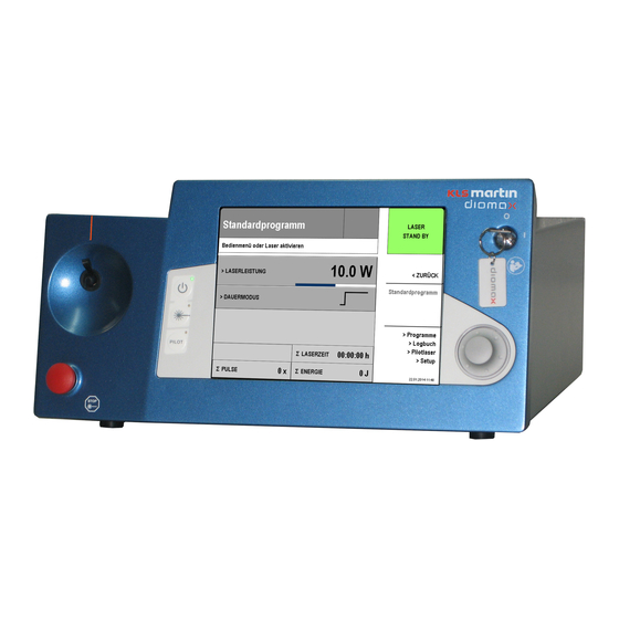
Service manual ® diomax MDL20 Functional description of the front panel Fig. 3-11: Front panel outside view 1 Emergency stop switch 5 Display 2 SMAX fibre connecting socket 6 Rotary switch 3 Laser signal lamp/optical fibre status 7 Keylock switch 4 Keypad The front panel is a support for the CPU board and the basis board including the CFL converter on the inside. - Page 21 Service manual ® diomax MDL20 The Keypad (4, fig. 3.11) features: A STANDBY button (green LED). Operating this button switches the laser to STANDBY • mode (laser not ready for use). While it is possible to set laser parameters in this state, no laser light can be emitted except the pilot laser light.
-
Page 22: Functional Description Of The Loudspeaker
Service manual ® diomax MDL20 Functional description of the loudspeaker ® The unit features different acoustic signals to indicate specific diomax activities via the loudspeaker which is located at the rear end of the unit: Laser activation tone: triple tone (triad) sounded during emission of laser radiation •... -
Page 23: Functional Description Of The Can And Rs 232 Interface
Service manual ® diomax MDL20 Functional description of the CAN and RS 232 interface ® The diomax features two serial interfaces which are located at the rear end of the unit: ® The RS 232 serial interface is intended for integration of the diomax into an integrated •... -
Page 24: Disassembly And Replacement
Service manual ® diomax MDL20 Disassembly and replacement Cover removal and replacing Switch off the system and unplug the power cord from the main supply. Remove the laser fibre from the fibre connector at the front side. ® Put the diomax on a flat surface, which is inured to scratches. - Page 25 Service manual ® diomax MDL20 Fig. 4-2: Removing back cover screws 1 First step: remove two inner hex screws 2 Second step: remove four inner hex screws Use a hexagon screwdriver SW 2.5 to remove the two hexagon socket head screws at the ®...
-
Page 26: Removal/Replace Of The Front Panel
Service manual ® diomax MDL20 Removal/replace of the front panel Remove the cover as described in chapter 4.1. Remove the 4 screws holding the front panel onto the housing, 2 on each side, using a coon- ® spanner and gently lay the front panel beside the diomax (fig. - Page 27 Service manual ® diomax MDL20 Unplug all the connectors between the CPU board/basis board and the rest of the device (fig. 4.5). Fig. 4-5: Removing the connectors from the CPU board and the basis board 1 RS 232 serial connector cable 2 12V Cable [Sp 003] 3 Ribbon cable (40-pole) [Sp 004] 4 Ribbon cable (34-pole) [Sp 005]...
-
Page 28: Removal/Replace Of The Cpu Board
Service manual ® diomax MDL20 Removal/replace of the CPU board Remove the connectors between the CPU board and the components underneath and the 3 hexagon screws securing it, by using a 2.5 mm hexagon screwdriver (fig. 4.7). Remove the CPU board carefully from the basis board. Fig. -
Page 29: Removal/Replace Of The Basis Board
Service manual ® diomax MDL20 Removal/replace of the basis board Remove the housing as described in chapter 4.1, and the front panel and CPU board as described in chapters 4.2 and 4.3. Remove all the connectors from the basis board and the 5 Phillips screws securing the basis board onto the front panel (fig. -
Page 30: Removal/Replace Of The Tft Display Module
Service manual ® diomax MDL20 Removal/replace of the TFT display module Remove the housing as described in chapter 4.1, and the front panel and basis board as described in chapters 4.2 and 4.3. Remove the 4 Phillips screws securing the TFT display module onto the front panel by using a Phillips screwdriver (2, fig. -
Page 31: Removal/Replace Of The Rotary Encoder Led Pcb
Service manual ® diomax MDL20 4.8.1 Removal/replace of the rotary encoder LED PCB Remove the housing as described in chapter 4.1, and the front panel and basis board as described in chapters 4.2 and 4.3. Remove the TFT display as described in chapter 4.7. Remove the complete rotary encoder as described in chapter 4.8. -
Page 32: Removal/Replace Of The Rotary Knob Center
Service manual ® diomax MDL20 4.8.3 Removal/replace of the rotary knob center Remove the housing as described in chapter 4.1, and the front panel and basis board as described in chapters 4.2 and 4.5. Remove the TFT display as described in chapter 4.7. Remove the complete rotary encoder as described in chapter 4.8 and the rotary encoder LED PCB as described in chapter 4.8.1. -
Page 33: Removal/Replace Of The Rotary Encoder Light Ring
Service manual ® diomax MDL20 4.8.4 Removal/replace of the rotary encoder light ring Remove the housing as described in chapter 4.1, and the front panel and basis board as described in chapters 4.2 and 4.5. Remove the TFT display as described in chapter 4.7. Remove the complete rotary encoder as described in chapter 4.8 and the rotary encoder LED PCB as described in chapter 4.8.1. -
Page 34: Removal/Replace Of The Laser Activating Lamp Incl. Cable
NOTICE To remove the power switches a socket key is necessary which can be ordered from KLS Martin indicating the part no. 08-507-00-42 Remove the housing as described in chapter 4.1, and the front panel and basis board as described in chapters 4.2 and 4.5. Remove the TFT display as described in chapter 4.7. - Page 35 Service manual ® diomax MDL20 Remove the upper circuit element of each power switch by removing the slotted screws securing them (1, fig. 4.20). Fig. 4-20: Removing the slotted screws securing the power switches 1 Screws securing the power switches Remove the mounting ring securing the power switches by using a 16 mm socket key (1, fig.
-
Page 36: Removal/Replace Of The Diode Module Including Sensor Board
Service manual ® diomax MDL20 4.11 Removal/replace of the diode module including sensor board NOTICE The sensor board and diode module have always to be replaced together, as they are co- ordinated. NOTICE Always adjust the fibre connecting socket after removal of the diode module or cooling unit to ensure its perfect fit onto the front panel. - Page 37 Service manual ® diomax MDL20 Remove the 2 hexagon screws securing the laser power supply line cords using a 4,5 mm and a 3 mm hexagon screwdriver (1, fig. 4.23). Remove the 4 hexagon screws using a 2,5 mm hexagon screwdriver to release the diode module from the cooling unit (2, fig. 4.23). Fig.
-
Page 38: Removal/Replacement Of The Cooling Unit
Service manual ® diomax MDL20 4.12 Removal/replacement of the cooling unit NOTICE Always adjust the fibre connecting socket after removal of the diode module or cooling unit to ensure its perfect fit onto the front panel. See chapter 4.21 Remove the housing as described in chapter 4.1, and then remove the front panel as described in chapter 4.2. - Page 39 Service manual ® diomax MDL20 Remove the cooling device by gently pulling up the front part of it until it is no longer connected to the screws holding it onto the bottom part of the housing (1, fig. 4.27) and then sliding the unit in front direction until the fan is no more connected to the housing (2, fig.
-
Page 40: Removal/Replace Of The Junction Pcb
Service manual ® diomax MDL20 4.13 Removal/replace of the junction PCB Remove the housing as described in chapter 4.1, and then remove the front panel as described in chapter 4.2. Remove the cooling unit as described in chapter 4.12. Remove all connectors from the junction PCB and the 4 hexagon screws by using a 2,5 mm hexagon screw driver (fig. -
Page 41: Removal/Replace Of The Fan
Service manual ® diomax MDL20 4.15 Removal/replace of the fan Remove the housing as described in chapter 4.1, and then remove the front panel as described in chapter 4.2. Remove the cooling unit as described in chapter 4.12. Remove the fan power supply cord from the junction PCB (1, fig. -
Page 42: Removal/Replace Of The Power Supply Unit
Service manual ® diomax MDL20 4.16 Removal/replace of the power supply unit NOTICE Do not open the power supply unit; always replace the complete power supply unit! Remove the housing as described in chapter 4.1. Remove the front panel as described in chapter 4.2. - Page 43 Service manual ® diomax MDL20 Remove the 4 screws securing the power supply unit onto the bottom part of the housing using a coon-spanner/hex-screwdriver (1, fig. 4.34) Fig. 4-34: Removing the screws holding the power supply unit onto the housing 1 Screws securing the power supply unit Pull the power supply unit gently towards the front side until the connecting sockets are inside the housing to remove the unit (fig.
-
Page 44: Removal/Replace Of The Loudspeaker
Service manual ® diomax MDL20 4.17 Removal/replace of the Loudspeaker Remove the housing as described in chapter 4.1. Remove the front panel as described in chapter 4.2. Remove the cooling unit as described in chapter 4.12 and the main power supply unit as described in chapter 4.16. -
Page 45: Removal/Replace Of The Adapter Board
Service manual ® diomax MDL20 4.19 Removal/replace of the adapter board Remove the housing as described in chapter 4.1. Remove the front panel as described in chapter 4.2. Remove all connectors from the adapter board and the 4 philips screws securing it onto the power supply unit by using a philips screwdriver (fig. -
Page 46: Adjusting The Smax Fibre Connecting Socket
Service manual ® diomax MDL20 4.21 Adjusting the SMAX fibre connecting socket NOTICE Always adjust the fibre connecting socket after removal of the diode module or cooling unit to ensure its perfect fit onto the front panel. Remove the cover as described in chapter 4.1. The SMAX fibre connecting socket can be adjusted in 2 dimensions. - Page 47 Service manual ® diomax MDL20 Fig. 4.42 displays a correctly adjusted SMAX fibre connector. Fig. 4-42: Correctly adjusted SMAX fibre connector 1 SMAX fibre connector Fig. 4.43 displays a wrongly adjusted SMAX fibre connector. Fig. 4-43: Wrongly adjusted SMAX fibre connector 1 SMAX fibre connector Revision 3...
-
Page 48: Electrical Measurements
Service manual ® diomax MDL20 Electrical measurements ® diomax electrical system Revision 3... -
Page 49: Service Voltages
Service manual ® diomax MDL20 Service voltages Following service voltages can be measured: Voltage Reading component Measuring point +12V Adapter board X7/1 Grounding Adapter board X7/6 Basis board X403/8 Grounding Adapter board X7/6 +12V Basis board X403/1 Digital grounding Basis board X403/3 -12V Basis board... - Page 50 Service manual ® diomax MDL20 5.2.2 The +5V service voltage can be measured on the basis board which is mounted on the inside of the front panel, under the CPU board. The +5V measuring point is located at pin 8 of the X403 connector (1, fig.
-
Page 51: Component Power Supply Measurements
Service manual ® diomax MDL20 5.2.4 -12V The -15V service voltage can be measured on the basis board which is mounted on the inside of the front panel, under the CPU board. The -12V measuring point is located at pin 26 of the X403 connector (1, fig. -
Page 52: Testing High Current Safety Shutdowns
Service manual ® diomax MDL20 Testing high current safety shutdowns NOTICE ® Ensure that a laser fibre is connected to the diomax and the laser radiation concealed. Wear protective goggles according to DIN EN 207 during the test procedures. 5.4.1 Diode module shutdown when subject to current overflow To test if the diode module correctly shuts down when the power supply unit delivers an unexpected high current greater than 60 A, remove the metal cover as described in chapter... -
Page 53: Service Menu
Service manual ® diomax MDL20 Service Menu ® Switch the diomax on and wait for the self-test to be finished. Activate the user-interface by pushing the rotary switch once. To enter the service menu select the menu item SETUP by turning the rotary switch till the menu item is highlighted and then pushing the rotary switch. -
Page 54: Device Information
Service manual ® diomax MDL20 Device information Enter the menu item DEVICE INFORMATION by selecting the menu item and pushing down the rotary switch. The device information menu item displays the software version (1), the operating hours of the ® diomax (2), the laser operating hours (3) and the current calibration table (4). -
Page 55: Adjust
Service manual ® diomax MDL20 The incident log menu displays the date, time and description of the occurred incidents. Adjust Enter the menu item Adjust by selecting the menu item and pushing down the rotary switch. Inside the adjust menu item you can set the ®... -
Page 56: Calibrate
Service manual ® diomax MDL20 Calibrate NOTICE ® Connect an operational optic fibre to the diomax before entering the CALIBRATE menu item, which will be indicated by a green LASER STANDBY sign on the display. For external power measurements use a calibrated laser power meter! Enter the menu item CALIBRATE by selecting the menu item and pushing down the rotary switch. -
Page 57: Cooling
Service manual ® diomax MDL20 The calibrate menu allows you to adjust the ® power settings of the diomax laser by measuring the effective power delivered using a laser power meter and correcting the internal value if necessary. Adjust the necessary current to reach 20W (Step 1, fig. - Page 58 Service manual ® diomax MDL20 Enter the menu item COOLING by selecting the menu item and pushing down the rotary switch The cooling menu item displays the temperature, peltier current, PWM signal, reference temperature and settings of the PID controller of the diode module/peltier element (1) as well as the temperature, PWM signal, reference temperature, PID controller settings and excluded range of the heatsink/fan (2).
-
Page 59: Reset Logfile
Service manual ® diomax MDL20 Reset logfile Enter the menu item RESET LOGFILE by selecting the menu item and pushing down the rotary switch. Select the item menu YES to confirm the reset of the logfile. Revision 3... -
Page 60: Reset All Settings
Service manual ® diomax MDL20 Reset all settings Enter the menu item RESET ALL SETTINGS by selecting the menu item and pushing down the rotary switch. Select the item menu YES to confirm the reset of all settings. Activating the TESTIO-display The temperature, current and voltage of specific ®... -
Page 61: Flash Updater By Kls Martin
Upon version 3.0 it is possible for the service technician to update a new firmware using the KLS Martin flash updater software. For this purpose a personal computer with a RS232 serial port, a RS232 cable and the latest version of the KLS Martin Flash updater is necessary. ®... -
Page 62: Diomax ® Status Codes
Service manual ® diomax MDL20 ® diomax status codes Status- First step Second step Service operation Error description Code done by user done by user done by technician 1001 Memory error Power off and on call service Replace hardware Footswitch Don’t operate the Check if footswitch 1002... - Page 63 Service manual ® diomax MDL20 Status- First step Second step Service operation Error description Code done by user done by user done by technician Atmel CPU clock Replace CPU and 1018 and C167 CPU clock Power off and on call service basis board not synchronized Confirm and correct...
- Page 64 Service manual ® diomax MDL20 Status- First step Second step Service operation Error description Code done by user done by user done by technician C167 CPU did not send vaues to Replace CPU and 2013 Power off and on Call service atmel CPU after basis board emission...
- Page 65 Service manual ® diomax MDL20 Status- First step Second step Service operation Error description Code done by user done by user done by technician C167 CPU did not 2037 Power off and on call service Calibrate send PULSETIME PULSETIME bad 2038 value during display Power off and on...
- Page 66 Service manual ® diomax MDL20 Status- First step Second step Service operation Error description Code done by user done by user done by technician CPLD Pulse signal 2054 Power off and on call service Calibrate failed 2055 CPLD pulse too long Power off and on call service Calibrate...
- Page 67 Service manual ® diomax MDL20 Status- First step Second step Service operation Error description Code done by user done by user done by technician Photodiode 2 value 2081 high (pulsphase Power off and on call service high) Photodiode 1 value 2082 Power off and on call service...
- Page 68 Service manual ® diomax MDL20 Status- First step Second step Service operation Error description Code done by user done by user done by technician Software error in Run new software 9006 memory Power off and on call service and calibrate administration System not Run new software...
- Page 69 Ophir no. 7Z0260830 Laser power meter, CW to 30W, intermittent to thermal head 150W www.ophiropt.com KLS Martin part Socket key for power Key for removal/replace of switches the power switches no. 08-507-00-42 KLS Martin part Unit to test the operability...
- Page 70 Service manual ® diomax MDL20 Spare parts and Accessories NOTICE When ordering spare parts or accessories from KLS Martin please indicate the part number. Identifier Part no. number Metal cover 08-507-00-07 Front with foils 08-507-00-06 12 V cable 08-507-00-36 Ribbon cable 40-pole...
- Page 71 Service manual ® diomax MDL20 Identifier Part no. number Temperature sensor 08-507-00-28 Fan incl. cable 08-507-00-30 Power supply unit 08-507-00-02 Loudspeaker incl. cable 08-507-00-31 RS 232 and CAN connector incl. cable 08-507-00-38 Adapter board 08-507-00-14 Plug-in feet (4 pieces) 08-507-00-08 ®...
- Page 72 Gebrüder Martin GmbH & Co. KG A company of the KLS Martin Group KLS Martin Platz 1 · 78532 Tuttlingen · Germany Postfach 60 · 78501 Tuttlingen · Germany Tel. +49 7461 706-0 · Fax 706-193 info@klsmartin.com · www.klsmartin.com Date of Release: 2010-10 ·...
Need help?
Do you have a question about the diomax MDL20 and is the answer not in the manual?
Questions and answers