Advertisement
Available languages
Available languages
Quick Links
INSTRUCTION
EN
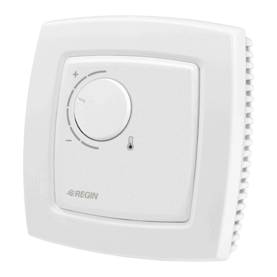
REGIO RC-T
i
Read this instruction before installation
and wiring of the product
Room controller with two outputs for valves
with three-point actuators
RC-T is a room controller from the Regio Mini series, intended to
control heating and cooling in a zone control system. It has four digital
outputs for controlling two valves with three-point actuators (increase-
decrease). Installation is directly on the wall or on an electrical connec-
tion box. The controller does not have a communication connection.
Technical data
Supply voltage
18...30 V AC, 50...60 Hz
Internal consumption
2.5 VA
Ambient temperature
0...50°C
Ambient humidity
Max 90% RH
Storage temperature
-20...+70°C
Built-in temperature sensor NTC Type, range 0...50°C, accuracy
+/-0.5°C at 15...30°C
Running time,
3-position actuators
120 s
Inputs and outputs
Refer to connection illustrations and table
below
Connection terminals
Lift type for cable cross-section 2.1 mm
Protection class
IP20
Material, casing
Polycarbonate, PC
Weight
110 g
Dimensions
95 x 95 x 31 mm
Installation
Place the controller in a location that has a temperature representative for
the room. A suitable location is approx. 1.6 m above floor level in a place
with unobstructed air circulation.
Remove the frame by depressing the locking tab in the lower edge of the
cover with a screwdriver. See figure 1.
Then prize out the electronics cassette using the four rectangular screwdri-
ver slots and levering against the edge of the bottom plate. See figure 2.
Note: Take care not to damage the electronics when inserting the screw-
driver into the slots.
Figure 1
The bottom plate with terminals has a number of fixing hole combina-
tions. Select suitable holes (see figure 3) and screw the bottom plate onto
the wall or connection box, so that the arrows on the bottom plate point
upwards. Do not tighten the screws too hard!
With surface-mounted cabling, break-out suitable holes from the marks in
the plastic.
2
RC-T
Setpoint knob
LED
°C
°C
Figure 4. Connection diagram for RC-T
Figure 2
Figure 5. Alternative connection for terminals 31, UI1, and terminal 33, DI2/CI
10 11 12 13 14
20 21 22 23 24
UP
UP
68
60
30 31 32 33
40 41 42 43
Figure 3. Bottom plate with mounting alternatives and location of
terminals (dimensions in mm.)
30
AI1
G
10
31
UI1
G0
11
32
DI1
DO1
12
33
DI2/CI
DO2
13
DO3
14
40
+C
GDO
20
41
AGnd
G0
21
42
-
DO4
22
43
-
DO5
23
-
24
30
AI1
31
UI1
32
DI1
33
DI2/CI
40
+C
41
AGnd
42
-
43
-
24 V AC
G0
G
1
Advertisement

Related Manuals for Regin REGIO RC-T


Summary of Contents for Regin REGIO RC-T
- Page 1 INSTRUCTION Weight 110 g REGIO RC-T Dimensions 95 x 95 x 31 mm 10 11 12 13 14 20 21 22 23 24 Setpoint knob 30 31 32 33 40 41 42 43 Figure 3. Bottom plate with mounting alternatives and location of terminals (dimensions in mm.)
- Page 2 (FS) See also section Occupancy detector below. 12 and terminal 20, GDO. Not used DI2/CI Regin’s condensation detector, KG-A/1 (FS). The For three-point actuator, heating increase or sensor is connected between terminals 33 and 41, External sensor, Internal sensor, Temperature cooling increase via change-over.
-
Page 3: Installation
Contact 10 minutes of non-occupancy (no signal from presence detector). REGIO RC-T AB Regin, Box 116, 428 22 Kållered, Sweden Preset operating mode Tel: +46 31 720 02 00, Fax: +46 31 720 02 50 Occupied is the preset operating mode. It can be set to Stand-by with Läs denna instruktion innan produkten... - Page 4 Plocka därefter ur elektronikkassetten med hjälp av de fyra demonte- För trepunktsställdon, värme minska eller kyla °C ringshålen genom att bända mejseln mot kanten på bottenplattan. Se 24 V AC minska via change-over. 24 V AC-utgång, max figur 2. OBS! Var försiktig så att du inte kommer åt elektroniken när 0,5 A.
- Page 5 Occupied är det förinställda driftläget. Det kan ställas om till Stand-by med Tabell 3. Övriga dipswitchar dipswitch SW3. Se tabell 3 ovan. Kontakt Kommentar AB Regin, Box 116, 428 22 Kållered Stand-by Occupied (FI) Förinställt driftläge Närvarodetektor Tel: +46 31 720 02 00, Fax: +46 31 720 02 50 För lokal styrning av driftläget mellan Förinställt driftläge och Bypass...
- Page 6 ANLEITUNG Montage REGIO RC-T °C Der Regler muss an einem Ort montiert werden, an dem eine für den 24 V AC Raum repräsentative Temperatur herrscht. Eine geeigneter Ort dafür wäre in ca. 1,6 m Höhe über dem Boden an einer Stelle mit ungehinderter Diese Anleitung vor Installation und Ver- Luftzirkulation.
- Page 7 Siehe auch nachfolgenden Abschnitt Präsenz- melder. Nicht benutzt Für Dreipunktpunkt-Stellantrieb, Heizen auf oder Kühlen auf über Umschaltrelais. 24 V AC- DI2/CI Regin-Kondensationsmelder, KG-A/1 (WE). Der Externer Fühler, Interner Fühler, Temperaturfühler Ausgang, max. 0,5 A. Stellantriebsklemme für Fühler wird zwischen Klemmen 33 und 41 (AGnd)
- Page 8 Ort zu steuern, wird ein Präsenzmelder angeschlossen. de réguler le chauffage et le refroidissement dans les systèmes de Regin Controls Deutschland GmbH contrôle de zones. Ce régulateur est doté de quatre sorties digitales Tel: +49 30 77 99 40, Fax: +49 77 99 479 Offenes Fenster qui permettent de contrôler deux vannes avec des actionneurs 3 points...
- Page 9 0,5 A. Un actionneur 24 V AC est connecté entre Pour le câblage apparent, utiliser les embouts perforables. DI2/CI Détecteur de condensation de Regin, KG-A/1 les bornes 12 et 20 (GDO). (RU). Le détecteur est branché sur les bornes 33 Pour l’actionneur 3 points, augmentation du...
- Page 10 (RU) rature Contact entre le mode de fonctionnement préréglé et le mode By-pass. Regin Control SARL, 32 rue Delizy, 93500 Pantin Réglages Tél : 01 71 00 34, Fax : 01 71 46 46 Fenêtre ouverte www.regin.fr, info@regin.fr Le chauffage et le refroidissement sont arrêtés.
Need help?
Do you have a question about the REGIO RC-T and is the answer not in the manual?
Questions and answers