Advertisement
Available languages
Available languages
Quick Links
INSTRUCTION
EN
REGIO RC-F
i
Read this instruction before installation
and wiring of the product
Room controller with fan switch
RC-F is a room controller from the Regio Mini series, intended to con-
trol heating and cooling in a zone control system. It has a switch for
controlling a three-speed fan (fan coil). Installation is directly on the
wall or on an electrical connection box. The controller does not have a
communication connection.
Technical data
Supply voltage
18...30 V AC, 50...60 Hz
Internal consumption
2.5 VA
Ambient temperature
0...50°C
Ambient humidity
Max 90% RH
Storage temperature
-20...+70°C
Built-in temperature sensor
NTC Type, range 0...50°C, accuracy
+/-0.5°C at 15...30°C
Inputs and outputs
Refer to connection illustrations and
table below
Connection terminals
Lift type for cable cross-section 2.1 mm
Protection class
IP20
Material, casing
Polycarbonate, PC
Weight
110 g
Dimensions
95 x 95 x 31 mm
Installation
Place the controller in a location that has a temperature representative for
the room. A suitable location is approx. 1.6 m above floor level in a place
with unobstructed air circulation.
Remove the frame by depressing the locking tab in the lower edge of the
cover with a screwdriver. See figure 1.
Then prize out the electronics cassette using the four rectangular screwdri-
ver slots and levering against the edge of the bottom plate. See figure 2.
Note: Take care not to damage the electronics when inserting the screw-
driver into the slots.
Figure 1
The bottom plate with terminals has a number of fixing hole combina-
tions. Select suitable holes (see figure 3) and screw the bottom plate onto
the wall or connection box, so that the arrows on the bottom plate point
upwards. Do not tighten the screws too hard!
With surface-mounted cabling, break-out suitable holes from the marks in
the plastic.
2
RC-F
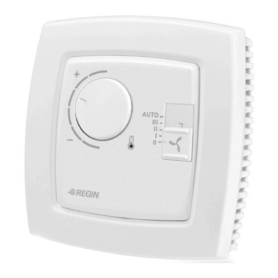
Setpoint knob
Fan switch
LED
°C
°C
Figure 4. Connection diagram for RC-F
Figure 2
10 11 12 13 14
20 21 22 23 24
UP
UP
68
60
30 31 32 33
40 41 42 43
Figure 3. Bottom plate with mounting alternatives and location of
terminals (dimensions in mm.)
30
AI1
G
10
24 V AC
31
UI1
G0
11
32
DI1
DO1
12
12
13
33
DI2/CI
DO2
13
14
DO3
14
20
40
+C
GDO
20
G
41
AGnd
G0
21
G0
Y
42
-
DO4
22
G
43
-
UO1
23
G0
UO2
24
Y
G
G0
30
AI1
G
10
31
UI1
G0
11
32
DI1
DO1
12
33
DI2/CI
-
13
-
14
40
+C
GDO
20
41
AGnd
G0
21
42
-
-
22
43
-
UO1
23
UO2
24
Figure 5. Alternative connection for terminals 31, UI1, and terminal
33, DI2/CI, terminal 23, UO1, and terminal 24, UO2.
L
RB3
30
I
31
II
M
N
32
III
33
1
Advertisement

Related Manuals for Regin REGIO RC-F


Summary of Contents for Regin REGIO RC-F
- Page 1 INSTRUCTION REGIO RC-F Setpoint knob 10 11 12 13 14 20 21 22 23 24 Fan switch 30 31 32 33 40 41 42 43 Installation Figure 3. Bottom plate with mounting alternatives and location of Place the controller in a location that has a temperature representative for terminals (dimensions in mm.)
- Page 2 24 V AC (digital output terminal 14 and terminal 20, GDO. DI2/CI Regin’s condensation detector, KG-A/1 (FS). The function) the controller utilizes time-proportional 24 V AC out common for DO. Internally connec- sensor is connected between terminals 33 and control to give a smooth control of the connected ted to terminal 10, G.
- Page 3 Preset operating mode and Bypass. This setting is used when UO1 is connected to a thermal ac- Contact tuator of type Regin RTAM-24 (NC). In the event of a power Open window AB Regin, Box 116, 428 22 Kållered, Sweden cut the valve will close.
- Page 4 INSTRUKTION Se figur 2. OBS! Var försiktig så att du inte kommer åt elektroniken när du REGIO RC-F sticker in mejseln i demonteringshålen. Läs denna instruktion innan produkten DI2/CI monteras och ansluts AGnd Rumsregulator med fläktomkopplare RC-F är en rumsregulator i Regio Mini-serien avsedd att styra värme och kyla i efterbehandlingssystem.
- Page 5 Denna inställning används vid anslutet termiskt ställdon typ SW8. Denna inställning refererar till vilken typ 24 V DC ut gemensam för DI och UI (vid digital Regin RTAM-24 (NC) på UO1. Vid ev. spänningsavbrott i av termiskt ventilställdon, NC eller NO man vill funktion) systemet stänger ventilen.
-
Page 6: Installation
Värme och kyla är bortkopplade. Kontakt Indice de protection IP20 Matière, boîtier Polycarbonate, PC AB Regin, Box 116, 428 22 Kållered Poids 110 g Börvärde Tel: +46 31 720 02 00, Fax: +46 31 720 02 50 Dimensions 95 x 95 x 31 mm Lokal börvärdesförskjutning (+/-3°C) ställs in med ratten på... - Page 7 Note : Attention à ne pas endommager la carte électronique avec le Contrôle du chauffage ou du refroidissement avec tournevis. fonction change-over. Pour des moteurs de vannes 0...10 V DC, max. 5 mA (RU) : La borne du signal de commande DI2/CI 0...10 V de l'actionneur est branchée à...
- Page 8 Lors- Sortie digitale Sortie analogique Borne 23, UO1. DI2/CI Détecteur de condensation de Regin, KG-A/1 que la fonction change-over n’est pas utilisée il faut laisser l’entrée pour actionneur pour moteur de déconnectée.
- Page 9 (22°C) et de refroidissement (24°C) réglées par Raumregler mit Ventilatorschalter Regin Control SARL, 32 rue Delizy, 93500 Pantin défaut. Ces valeurs peuvent être modifiées à l’aide des microswitchs Tél : 01 41 71 00 34, Fax : 01 41 71 46 46 Der RC-F ist ein Raumregler aus der Regio Mini-Reihe, der für die...
- Page 10 Ausgangssignal Heizen oder Kühlen mit Change- Over. Für 0...10 V DC-Ventilstellantrieb, max. 5 mA DI2/CI (WE). Die 0…10 V-Eingangsklemme des Stellantriebs wird an Klemme 23, und dessen Spannungsversorgung an Klemme 10 und 11 AGnd angeschlossen. Stellen Sie sicher, dass das Bezugspotential G0 an die korrekte Klemme am Stellantrieb angeschlossen ist.
- Page 11 Diese Einstellung wird für UO1 bei Anschluss eines thermi- men 33 und 40 (+C) angeschlossen. Geschlosse- Präsenzmelder schen Stellantriebs der Sorte Regin RTAM-24 (NG) verwen- ner Kontakt entspricht geschlossenem Fenster. Um das Umschalten zwischen Standard-Betriebsmodus und Bypass det. Im Falle einer Spannungsunterbrechung schließt das vor Ort zu steuern, wird ein Präsenzmelder angeschlossen.
- Page 12 Anzeige (rot oder blau) deutet auf einen Einstellungsfehler hin. Dieses Produkt trägt das CE-Zeichen. Mehr Information können Sie auf www.regincontrols.de finden. Kontakt Regin Controls Deutschland GmbH Tel: +49 30 77 99 40, Fax: +49 30 77 99 479 www.regincontrols.de, info@regincontrols.de RC-F...
Need help?
Do you have a question about the REGIO RC-F and is the answer not in the manual?
Questions and answers