Advertisement
Available languages
Available languages
Quick Links
INSTRUCTION
EN
RVAN25-24A
i
Read this instruction before installation
and wiring of the product
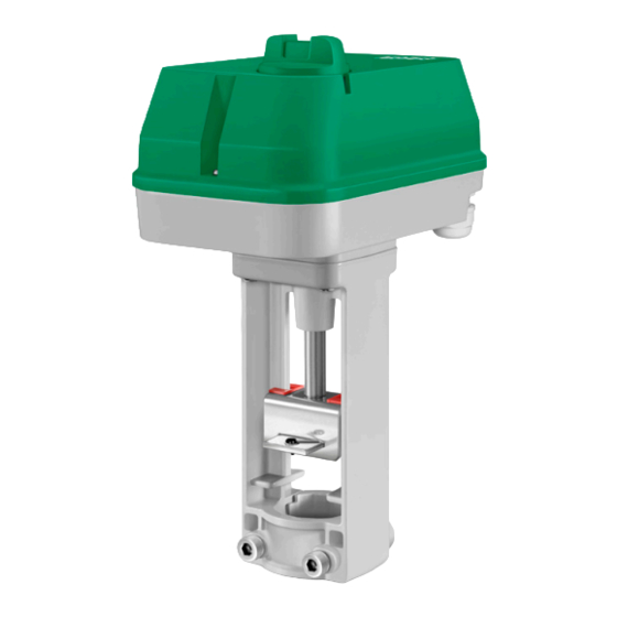
Valve actuator for 0(2)...10 V control
RVAN25-24A is a valve actuator designed for control of Regin valves.
The actuator has automatic self stroke adjustment and can be oper-
ated manually.
Technical data
Supply voltage
24 V AC ±15 %, 50/60 Hz
or 24 V DC ±15 %
Control signal
0(2)...10 V DC
Max. power consumption
8.6 W / 22.4 VA
Stroke
10...52 mm
Stroke time
3 s/mm
Force
2500 N
Ambient temperature
0...50°C
Storage temperature
-40...80°C
Ambient humidity
10...90 % RH
Dimensions (WxHxD)
198 x 309 x 133 mm
Protection class
IP54
Installation
If the valve stem lock and valve throat adaptor are not already mounted
on the valve, mount them. Pull the valve stem out as far as possible.
Remove the screws (hex key 6 mm) and clamp from the actuator yoke.
Depress the spring-loaded tab on the drive rod coupling device and fit the
valve stem into the coupling.
Release the tab to connect the valve to the actuator. The position of the
yoke on the valve stem adaptor must be adjusted so that the clamp screw
holes line up with the groove in the valve throat adaptor. If the drive rod
needs to be moved in or out for this, depress the central button of the
control knob and turn it clockwise to extend the drive rod and counter-
clockwise to retract it (see Manual override). Mount the screws and the
clamp. Tighten the screws until the actuator is firmly attached.
Disassembly takes place in reverse order.
Mounting positions
90º
Wiring
U
5
Measuring voltage
for position indication
U 0...10 V DC
Signal neutral
Y 0(2)...10 V DC
Control signal from
controller
RVAN25-24A
Stroke and end position calibration
Stroke and end position calibration is not necessary due to a con-
struction utilizing end position stops. When the valve reaches the end
position, a force is generated. Once the force of the actuator reaches
a predefined level, the limit switch automatically halts the drive motor.
Override
Activation of the override input will force the valve to the maximum
open position.
Manual override
90º
To manually set the valve position, first depress the central part of the
knob, until it clicks and remains depressed (1 in the figure). Then the
valve position can be changed manually by turning the knob (2 in the
figure). When the knob is turned clockwise, the drive rod is pushed
G0
G
outwards and when the knob is turned anti-clockwise, the drive rod is
B
M
Y
pulled inwards.
4
3
2
1
6
To return to normal operation, set the knob so that it is in line with the
text "Auto" on the cover. Then depress the outer parts of the knob (3
in the figure). The central depressed part will pop out, and the actua-
tor will return to normal operation.
Note: After any manual operation the actuator will always run through
a zero point calibration.
DIP switches
There are six DIP switches for setting different functions. Follow the
table below for setting the DIP switches.
Adjusted settings will be valid only after the next power-on.
24 V AC/DC
1
Advertisement

Related Manuals for Regin RVAN25-24A


Summary of Contents for Regin RVAN25-24A
- Page 1 When the knob is turned clockwise, the drive rod is pushed outwards and when the knob is turned anti-clockwise, the drive rod is RVAN25-24A is a valve actuator designed for control of Regin valves. pulled inwards. The actuator has automatic self stroke adjustment and can be oper- To return to normal operation, set the knob so that it is in line with the ated manually.
-
Page 2: Installation
The new setting will be with the setting of SW6 valid after the next power on. RVAN25-24A är ett ventilställdon för styrning av Regins ventilsorti- 5(6)...10 V = 0...100 % 0(2)...5(6) V = 0...100 % (FS) ment. Ställdonet har automatisk slaglängdsjustering och går att styra... - Page 3 SW1 Ventilens arbetsriktning eller så gick ventilens slaglängd förlorad Ventilen är stängd när spindeln är i sitt nedre läge. Off: Ventilen är stängd när spindeln är i sitt övre läge. Rött ljus som blinkar snabbt Manuellt överstyrningsläge RVAN25-24A...
- Page 4 Vid kylventil ska den blå markeringen vara i läge för helt öppen ventil Ventilstellantrieb für 0(2)...10 V-Ansteuerung och den röda markeringen i läge för helt stängd ventil. RVAN25-24A ist ein Stellantrieb für die Ansteuerung von Regin Ventilen. Anschluss Der Stellantrieb ist mit automatischer Hubanpassung und Handbedienung Denna produkt är CE-märkt.
- Page 5 SW1 Wirkrichtung des Ventils Installation oder fehlender Hubweg On: Das Ventil ist geschlossen, wenn sich die Spindel in der Rotes, schnell blinkendes Manueller Eingriffsmodus niedrigsten Position befindet. Licht Off: Das Ventil ist geschlossen, wenn sich die Spindel in der höchsten Position befindet. RVAN25-24A...
- Page 6 90º 90º à l’installation et au raccordement de l’appareil. Moteur de vanne pour contrôle 0(2)...10 V L’actionneur RVAN25-24A est prévu pour le pilotage de vannes Raccordement Regin. L’ajustement de la course est automatique. Le moteur dispose d’une commande manuelle. Pour régler manuellement la position de la vanne, appuyez sur la partie centrale du bouton jusqu’à...
- Page 7 SW2 Caractéristiques de débit Voyant vert clignotant Test en cours Regin FRANCE, 32 rue Delizy, 93500 Pantin On : Donne les caractéristiques de débit linéaires avec des vannes à rapidement Tél : +33(0)1 71 00 34, Fax : +33(0)1 71 46 46 pourcentage égal.
Need help?
Do you have a question about the RVAN25-24A and is the answer not in the manual?
Questions and answers