FLENDER ZAPEX Assembly And Operating Instructions Manual

FLENDER ZAPEX Assembly And Operating Instructions Manual

Hide thumbs Also See for ZAPEX:
Table of Contents

Advertisement

Quick Links

ZAPEX
Assembly and operating instructions M3560-02en
Edition 09/2022
ZNN, ZNNA, ZNNV, ZNZS, ZNZA, ZNZV

Advertisement

Table of Contents
loading

Summary of Contents for FLENDER ZAPEX

  • Page 1 ZAPEX Assembly and operating instructions M3560-02en Edition 09/2022 ZNN, ZNNA, ZNNV, ZNZS, ZNZA, ZNZV...
  • Page 2 Original assembly and operating instructions M3560-02 Edition 09/2022 22/11/2022 Copyright (©2022 Flender GmbH) 15:14:08...
  • Page 3: Table Of Contents

    Table of contents Introduction...............................11 Legal information ........................11 About these instructions......................12 Text attributes ..........................12 Copyright..........................13 Safety information ............................15 General information .........................15 Intended use ..........................17 Safety information for a coupling when used in potentially explosive atmospheres ....17 2.3.1 Marking ............................17 2.3.2 Conditions of use ........................18 General warning notices ......................19 Description ..............................21...
  • Page 4 Table of contents 5.3.2.4 Angular and radial misalignment....................35 Fill with lubricant ........................36 5.4.1 Lubricant ..........................36 5.4.2 Filling quantity ..........................37 5.4.3 Fill with lubricant ........................38 Commissioning............................39 Operation..............................41 Normal operation of the coupling .....................41 Fault – causes and correction ....................41 7.2.1 Procedure in the event of faults ....................41 7.2.2 Identifying the fault cause ......................41 7.2.2.1...
  • Page 5 Table of contents 11.2.3 Screw plug ..........................60 Technical specifications ..........................61 Speeds, geometry data and weights..................61 A.1.1 Dimension drawing for ZNN and ZNNA types ................. 61 A.1.2 Dimension drawing for ZNZS and ZNZA types ................ 62 A.1.3 Dimension drawing for ZNNV types ..................63 A.1.4 Dimension drawing for ZNZV types ..................64 A.1.5...
  • Page 6 Table of contents Edition 09/2022 M3560-02en...
  • Page 7 List of tables Table 2-1 General warnings ........................15 Table 2-2 Temperature classes for explosive atmospheres as a result of gases, vapours or mists ..18 Table 4-1 Types of preservative agents for long-term storage..............24 Table 5-1 Recommended assigned fits for bores with parallel key connection..........26 Table 5-2 Diameter and axial position of the threaded hole, tightening torque and width A/F ....28 Table 5-3...
  • Page 8 List of tables Edition 09/2022 M3560-02en...
  • Page 9 List of figures 
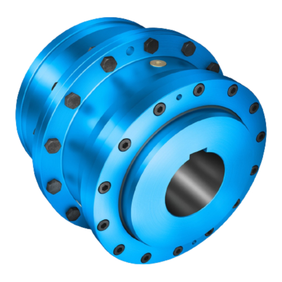
Figure 3-1 ZNN, ZNNA, ZNZS, ZNZA, ZNNV and ZNZV types..............22 Figure 4-1 Transport symbols........................23 Figure 5-1 Tolerances for the finished bore in coupling part 1 (1) or 2 (2) ..........27 Figure 5-2 Diameter and axial position of the threaded hole in the hub .............28 Figure 5-3 Position of the balancing bore for two-plane balancing..............30 Figure 5-4...
  • Page 10 List of figures Edition 09/2022 M3560-02en...
  • Page 11: Introduction

    Introduction Legal information 1.1 Legal information Warning system These instructions contain information you must observe for your own personal safety as well as to avoid damage to property and persons. The information regarding your personal safety is highlighted with a warning triangle. Information exclusively regarding property dam- age alone is not marked with a warning triangle.
  • Page 12: About These Instructions

    Please note the following: WARNING Flender products are only suitable for the uses set out in the catalogue and associated technical documentation. If third-party products and components are used, these must be recommended and/or authorised by Flender. Safe and flawless operation of the products requires proper transport, proper storage, setup, assembly, installation, commissioning, operation and maintenance.
  • Page 13: Copyright

    (1) Numbers in brackets are part numbers. Copyright 1.4 Copyright The copyright of these instructions is held by Flender. These instructions must not be used wholly or in parts without our authorisation or be given to third parties. If you have any technical queries, please contact our factory or one of our service outlets (refer to Service and support (Page 53)).
  • Page 14 Introduction 1.4 Copyright Edition 09/2022 M3560-02en...
  • Page 15: Safety Information

    Only the knowledge of these instructions can avoid faults on the coupling and ensure fault- free and safe operation. Non-adherence to the instructions can cause product or property damage or personal injury. Flender does not accept any liability for damage or operating fail- ures that are due to non-adherence to these instructions.
  • Page 16: Table 2-1 General Warnings

    Safety information 2.1 General information ANSI Warning Warning – hand injuries Explosion protection approval Table 2-1: General warnings Explanation regarding regulation 2008 No. 1597 The couplings described here are “components” in accordance with the regulation 2008 No. 1597 and do not require a UK declaration of incorporation. Explosion Protection Directive The term “Explosion protection regulations”...
  • Page 17: Intended Use

    • Do not make any modifications to the coupling that go beyond the permissible machining described in these instructions. This also applies to touch protection facilities. • Use only original replacement parts from Flender. Flender only accepts liability for ori- ginal replacement parts from Flender.
  • Page 18: Conditions Of Use

    Safety information 2.3 Safety information for a coupling when used in potentially explosive atmospheres 2.3.2 Conditions of use 2.3 Safety information for a coupling when used in potentially explosive atmospheres Note also the material-dependent permissible ambient temperature of the O-ring (12) ac- cording to chapter O-rings (Page 69).
  • Page 19: General Warning Notices

    Safety information 2.4 General warning notices • If you want to use a coated coupling in potentially explosive atmospheres, please note the requirements concerning the conductivity of the paint and the limitation on the paint layer thickness applied in accordance with EN 80079-36. No build-up of electrostatic charges is to be expected with a paint layer thickness of less than 200 μm.
  • Page 20 Safety information 2.4 General warning notices WARNING Risk of chemical burns from chemical substances There is a risk of chemical burns when handling aggressive cleaning agents. • Please observe the manufacturer’s instructions on how to handle cleaning agents and solvents. •...
  • Page 21: Description

    Structure The ZAPEX coupling consists of the two hub parts (1) and (2) with external teeth, which are fitted onto the machine shafts. The external teeth engage in a flanged sleeve (5) in each case, which has corresponding internal teeth.
  • Page 22: Figure 3-1 Znn, Znna, Znzs, Znza, Znnv And Znzv Types

    Description The diagrams show the various types with their constituent parts and their part numbers. Figure 3-1: ZNN, ZNNA, ZNZS, ZNZA, ZNNV and ZNZV types Coupling part 1/2 Coupling part 1/2 Spacer Flanged sleeve Screw plug Sealing ring in size 83 Fitting bolt Hexagon nut O-rings Plate pulley...
  • Page 23: Application Planning

    Application planning Check the delivery for damage and for completeness. Report any damage and/or missing parts to Flender immediately. The coupling is delivered in individual parts and preassembled groups. Transport of the coupling 4.1 Transport of the coupling WARNING Severe personal injury due to improper transport Severe personal injury due to falling components or due to crushing.
  • Page 24: Table 4-1 Types Of Preservative Agents For Long-Term Storage

    Application planning 4.2 Storage of the coupling • If the coupling contains elastomer components, ensure that there are no devices in the storage room that produce ozone, such as fluorescent lights, mercury vapour lamps or high-voltage electrical equipment. • Store the coupling on suitable supports or in suitable containers. Long-term storage NOTICE Property damage due to improper long-term storage...
  • Page 25: Assembly

    • Balancing the coupling (Page 30) Information The customer is responsible for execution of the finishing work on the coupling. Flender shall have no liability whatsoever for claims under warranty arising from finishing work that has not been carried out adequately.
  • Page 26: Mill The Finished Bore

    Assembly 5.1 Preparatory work 5.1.1 Mill the finished bore 5.1 Preparatory work The diameter of the finished bore depends on the shaft used. Recommended assigned fits In the following table you can find the recommended assigned fits for bores with a parallel key connection.
  • Page 27: Mill The Parallel Keyway

    The coupling part 1/2 (1 or 2) is secured by a set screw or an end plate to prevent axial movements. Please consult Flender if you want to use an end plate. Note the following when using a set screw: •...
  • Page 28: Figure 5-2 Diameter And Axial Position Of The Threaded Hole In The Hub

    Assembly 5.1 Preparatory work When arranging the threaded hole, note the difference between the A or B variant of the coupling part 1 (1) or 2 (2). Figure 5-2: Diameter and axial position of the threaded hole in the hub ① Sealing surface ②...
  • Page 29: Table 5-2 Diameter And Axial Position Of The Threaded Hole, Tightening Torque And Width A/F

    Assembly 5.1 Preparatory work Coupling size Finished Threaded hole Tightening Width A/F in- bore D torque TA ternal hexagon Over Up to Table 5-2: Diameter and axial position of the threaded hole, tightening torque and width A/F Apply the specified tightening torques as listed in Section Tightening procedure (Page 69). Position of the threaded hole with respect to the parallel keyway Position the threaded hole for the set screw on the parallel keyway.
  • Page 30: Balancing The Coupling

    Assembly 5.1 Preparatory work 5.1.4 Balancing the coupling 5.1 Preparatory work Notes on balancing NOTICE Property damage to coupling part 1 (1) or 2 (2) If you damage the gear or the sealing surface for the O-ring (12) on coupling part 1 (1) or 2 (2), the coupling part 1 (1) or 2 (2) is no longer allowed to be used for operation.
  • Page 31: Assembling Coupling Parts With Shaft-Hub Connection Using A Parallel Key

    Assembly 5.2 Mounting the coupling NOTICE Damage to property Damage to the shaft end, the coupling parts and/or the parallel key. • Note the handling instructions regarding assembly of the coupling parts. Assembly of the coupling comprises the following steps: •...
  • Page 32: Assembling Coupling Parts With Shaft-Hub Connection Using A Pressurised Oil Interference Fit

    Assembly 5.2 Mounting the coupling 9. Secure the coupling parts using a set screw or an end plate. When securing with a set screw, the shaft must not protrude or be set back from the inner side of the hub. After cooling to room temperature, fill the threaded hole for the set screw 2/3 full with sealing compound (50) to prevent the lubricant from escaping through the parallel key- way.
  • Page 33: Assembling The Coupling

    • Reduced wear • Reduced restoring forces • Misalignment reserves for operation of the coupling To achieve the longest possible coupling service life, Flender recommends running the coup- ling with 20% of the possible misalignments during operation (see Possible misalignment (Page 34)).
  • Page 34: Possible Misalignment

    Assembly 5.3 Aligning the coupling The recommended alignment values are specified as numerical values in Distances between teeth VA and recommended alignment values for angular and radial misalignment (Page 67) . Do not align the coupling more accurately than this, as the lubrication film form- ation will then be compromised.
  • Page 35: Radial Misalignment

    Assembly 5.3 Aligning the coupling For ND, the smallest hub diameter of ND1 or ND2 is to be used. ND1 or ND2 in mm see Speeds, geometry data and weights (Page 61) The alignment value for ΔS can be found in Section Distances between teeth VA and recom- mended alignment values for angular and radial misalignment (Page 67).
  • Page 36: Fill With Lubricant

    • Use greases of viscosity class NLGI 00 or NLGI 0 at an ambient temperature of -10 °C to +80 °C. List of lubricants To make it easier for users to select lubricants, Flender recommends products which have been properly tested and that satisfy Flender requirements. The recommended lubricants are available on the following link: https://www.flender.com/de/approvedlubricants...
  • Page 37: Filling Quantity

    Ambient temperature -10 °C to +80 °C Type ARAL Aralub FDP 00 Energrease LS-EP 00 Castrol Tribol GR 100 - 00 PD Flender Flender high-performance grease Fuchs Renolit SO-GFB Grafloscon C-SG 500 Plus ExxonMobil Mobilux EP004 Shell Gadus S2 V220 00 TotalEnergies...
  • Page 38: Fill With Lubricant

    Assembly 5.4 Fill with lubricant Coupling size Grease filling 0.04 0.08 0.16 0.33 0.42 quantity ZNN, ZNNA Grease filling 0.02 0.04 0.08 0.17 0.21 0.35 0.45 1.15 quantity ZNZS, ZNZA Table 5-3: Grease filling quantity For the ZNZS and ZNZA types, the grease filling quantities apply for one coupling side 5.4.3 Fill with lubricant 5.4 Fill with lubricant...
  • Page 39: Commissioning

    Commissioning DANGER Danger due to igniting deposits During use in potentially explosive atmospheres deposits from heavy metal oxides (rust) can ignite due to friction, impact or friction sparks and lead to an explosion. • Ensure through the use of an enclosure or other suitable measures that heavy metal oxide (rust) deposits on the coupling are not possible.
  • Page 40 Commissioning Edition 09/2022 M3560-02en...
  • Page 41: Operation

    Operation Normal operation of the coupling 7.1 Normal operation of the coupling The coupling runs quietly and shock-free during normal operation. Fault – causes and correction 7.2 Fault – causes and correction A form of behaviour which is different to normal operation is classed as a fault and has to be rectified immediately.
  • Page 42: Possible Faults

    Operation 7.2 Fault – causes and correction WARNING Physical injury Injury from rotating parts. • Only carry out work on the coupling when it is at a standstill. • Secure the drive aggregate against unintentional startup. • Attach an information notice to the start switch stating clearly that work is being carried out on the coupling.
  • Page 43: Possible Causes

    Operation 7.2 Fault – causes and correction Fault Cause Rectification Presence of vibrations Incorrect coupling assembly. Reassemble the coupling in compliance with these instructions. Check the possible causes given in sections Assembly-related causes Please observe all the stipulations and (Page 43) and Specific assembly-re- requirements given in chapter As- lated and maintenance-related causes sembly (Page 25).
  • Page 44: Maintenance-Related Causes

    7.2 Fault – causes and correction • Stipulated maintenance intervals not adhered to. • Replacement parts that were used were not original replacement parts from Flender. • Flender replacement parts that were used were old or damaged. • Leak in the area of the coupling not detected so that chemically aggressive substances damage the coupling.
  • Page 45: Correcting The Changed Alignment

    Operation 7.2 Fault – causes and correction 7.2.3.2 Correcting the changed alignment 7.2 Fault – causes and correction A changed alignment of the coupling during operation often occurs when the coupled ma- chines shift compared to one another. A cause of this can be loose foundation bolts. Procedure 1.
  • Page 46 Operation 7.2 Fault – causes and correction Edition 09/2022 M3560-02en...
  • Page 47: Maintenance

    Maintenance Maintenance intervals 8.1 Maintenance intervals DANGER Danger due to bursting of the coupling The coupling can burst if the maintenance intervals are not adhered to. There is a risk of fatal injury from flying fragments. Bursting of the coupling can lead to an explosion in po- tentially explosive atmospheres.
  • Page 48: Replacing O-Rings

    Maintenance 8.3 Replacing O-rings Information • When replacing the lubricant, keep the amount of remaining lubricant in the coupling as low as possible. • It’s easier to change the grease if you add low-viscosity oil to the old grease. Contact the manufacturer to confirm the compatibility of the oil with the grease in writing.
  • Page 49: Dismantling The Coupling

    Maintenance 8.4 Dismantling the coupling 1. Drain the grease according to Section Lubricant replacement (Page 48). 2. Loosen the bolt connection (8; 9) of the flanged sleeves (5) and/or the spacer (4). 3. Slide the flanged sleeve (5) off the gear teeth and off the hub until you can remove the O-ring (12).
  • Page 50: Dismantling Coupling Part 1 (1) Or 2 (2) With Shaft-Hub Connection Using Pressurised Oil Interference Fit

    Maintenance 8.4 Dismantling the coupling Procedure 1. Secure the coupling parts to prevent them from falling. 2. Remove the axial locking element (set screw, end plate). 3. Use a suitable pulling fixture. 4. Heat up the coupling part 1 (1) and/or 2 (2) using a burner above the parallel key along its length to maximum 80 °C.
  • Page 51 Maintenance 8.4 Dismantling the coupling NOTICE Risk of injury and danger to the environment from escaping oil. • Catch any oil which escapes. • Dispose of the oil according to the valid regulations. Tools required • One oil pump with pressure gauge (at least 2500 bar) per oil channel. Or: One motor-driven oil pump.
  • Page 52 Maintenance 8.4 Dismantling the coupling 11.Check the gear, sealing surfaces, hub bore and shaft for damage and protect them against corrosion. 12.Replace damaged parts. When reinstalling the coupling parts, please observe the information in chapters Assembly (Page 25) and Commissioning (Page 39). Edition 09/2022 M3560-02en...
  • Page 53: Service And Support

    Customer Service addresses: Flender GmbH Schlavenhorst 100 46395 Bocholt Germany Tel.: +49 (0)2871/92-0 Fax.: +49 (0)2871/92-2596 Flender GmbH (http://www.flender.com/) More information Further information about service and support can be found on the Internet: Service & Support (https://www.flender.com/service) M3560-02en Edition 09/2022...
  • Page 54 Service and support 9.1 Contact Edition 09/2022 M3560-02en...
  • Page 55: Disposal

    Disposal Disposal of the coupling Dispose of the coupling parts according to applicable national regulations or recycle them. M3560-02en Edition 09/2022...
  • Page 56 Disposal Edition 09/2022 M3560-02en...
  • Page 57: Replacement Parts

    By stocking the most important replacement parts at the installation site you can ensure that the coupling is ready for use at any time. Use only original replacement parts from Flender. Flender only accepts liability for original replacement parts from Flender.
  • Page 58: Spare Parts Drawing And Spare Parts List

    Sealing ring (7) is only available for size 83. For the other sizes, the sealing ring is incorporated into the screw plug (6). The plate pulley (20) is flanged into the spacer (4). As a replacement, Flender only supplies the com- plete spacer (4) with plate pullies (20). For the ZNZS type with spacer lengths LZ ≤ 200, the spacer (4) is designed without plate pullies (20).
  • Page 59: Spare Parts Drawing For Znn, Znna, Znnv, Znzs, Znza And Znzv Types

    Replacement parts 11.2 Spare parts drawing and spare parts list 11.2.2 Spare parts drawing for ZNN, ZNNA, ZNNV, ZNZS, ZNZA and ZNZV types 11.2 Spare parts drawing and spare parts list Figure 11-1: Spare parts drawing for ZNN, ZNNA, ZNNV, ZNZS, ZNZA and ZNZV types M3560-02en Edition 09/2022...
  • Page 60: Screw Plug

    Replacement parts 11.2 Spare parts drawing and spare parts list 11.2.3 Screw plug 11.2 Spare parts drawing and spare parts list The diagram below shows the screw plug (22): Figure 11-2: Screw plug (22) Edition 09/2022 M3560-02en...
  • Page 61: Technical Specifications

    Technical specifications Speeds, geometry data and weights Speeds, geometry data and weights In this chapter you can find dimension drawings and technical data for ZAPEX couplings of the following types: • Dimension drawing for ZNN and ZNNA (Page 61) type • Dimension drawing for ZNZS and ZNZA (Page 62) type •...
  • Page 62: Dimension Drawing For Znzs And Znza Types

    Technical specifications Speeds, geometry data and weights Figure A-2: Dimension drawing for ZNNA types A.1.2 Dimension drawing for ZNZS and ZNZA types Speeds, geometry data and weights The ZNZA type is only produced in variant A (S17). For clearance S8,S9, and S17, refer to Chapter Clearance S (Page 66).
  • Page 63: Dimension Drawing For Znnv Types

    Technical specifications Speeds, geometry data and weights Figure A-4: General ZNZA illustration A.1.3 Dimension drawing for ZNNV types Speeds, geometry data and weights For clearance S11 and S12, refer to Chapter Clearance S (Page 66). M3560-02en Edition 09/2022...
  • Page 64: Dimension Drawing For Znzv Types

    Technical specifications Speeds, geometry data and weights You can find the dimension table in Chapter Dimension table (Page 66). Figure A-5: ZNNV type ① ② bottom A.1.4 Dimension drawing for ZNZV types Speeds, geometry data and weights For clearance S8 and S13, refer to Chapter Clearance S (Page 66). S ‐...
  • Page 65: Figure A-6 Znzv Type

    Technical specifications Speeds, geometry data and weights You can find the dimension table in Chapter Dimension table (Page 66). Figure A-6: ZNZV type ① ② bottom M3560-02en Edition 09/2022...
  • Page 66: Dimension Table

    Technical specifications Speeds, geometry data and weights A.1.5 Dimension table Speeds, geometry data and weights Size Rated Speed  Bore Axial Weight torque D1, D2 back- min. lash from up to 1020 8500 2210 7700 4020 6900 129.5 6600 6200 17.5 11000 5800 25.5...
  • Page 67: Distances Between Teeth Va And Recommended Alignment Values For Angular And Radial Misalignment

    Technical specifications Distances between teeth VA and recommended alignment values for angular and radial misalignment Size perm perm De- Devi- viation ation S8, S9, S1, S2, S11, S12 10.5 +0.5 10.5 +0.5 15.5 12.5 +0.5 15.5 14.5 10.5 +0.5 14.5 16.5 12.5 +0.5...
  • Page 68: Tightening Torques And Widths A/F

    Technical specifications Tightening torques and widths A/F NOTICE As a result of the limited axial clearance, halve the alignment values forZNNA and ZNZA types. Size Distance between teeth Alignment values for radial misalignment Alignment values ΔKr for angular mis- alignment for VA1 for VA2 for VA5 or VA6...
  • Page 69: Tightening Procedure

    Technical specifications Tightening procedure Size Tightening torque TA Width A/F SW Part no. Part no. Table A-4: Tightening torques and widths A/F Hexagon socket Hexagon head Apply the specified tightening torques as listed in Section Tightening procedure (Page 69). Tightening procedure Tightening procedure Tightening torques must be observed taking into account the following table: Scatter of the torque ap- Tightening procedure...
  • Page 70: O-Rings

    Technical specifications O-rings • Avoid contact with aggressive media • Protect the O-rings (12) from becoming deformed during storage • Do not mount the O-rings (12) for storage onto the coupling part (1/2) A.6.2 O-rings O-rings Material Hardness Comment Marking Ambient temper- Approved for ex- ature...
  • Page 71: Declaration Of Conformity

    Declaration of conformity UK Declaration of Conformity UK Declaration of Conformity Product: FLENDER ZAPEX® couplings ZNN, ZNNA, ZNNV, ZNZS, ZNZA, ZNZV types Name and address of the manufacturer: Flender GmbH Schlavenhorst 100 46395 Bocholt Germany This Declaration of Conformity is issued under the sole responsibility of the manufacturer.
  • Page 72 Declaration of conformity UK Declaration of Conformity Edition 09/2022 M3560-02en...
  • Page 74 ZAPEX Assembly and operating instructions M3560-02en Edition 09/2022 Flender GmbH Alfred-Flender-Straße 77 46395 Bocholt Germany...

This manual is also suitable for:

ZnnZnnaZnnvZnzsZnzaZnzv

Table of Contents