AUSTRALIAN MONITOR HSv2 Series Installation And Operation Manual

AUSTRALIAN MONITOR HSv2 Series Installation And Operation Manual

Mixer amplifier

Advertisement

Quick Links

INSTALLATION AND OPERATION MANUAL
HS
SERIES
v
2
MIXER AMPLIFIER
HS60
/ HS120
/ HS250
v
v
v
2
2
2

Advertisement

Table of Contents
loading
Need help?

Need help?

Do you have a question about the HSv2 Series and is the answer not in the manual?

Questions and answers

Aleks Bojanic
June 5, 2025

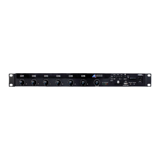
Hello there...I contact you from St Francis de Sales College, Mt Barker, South Australia...we have recently purchased 5 x HSv250v2 Mixer Amplifiers...I am having issues with a couple of them with the Bluetooth dropping off regularly...is this an issue that you have struck before? Thank you, Aleks

Subscribe to Our Youtube Channel

Summary of Contents for AUSTRALIAN MONITOR HSv2 Series

  • Page 1 INSTALLATION AND OPERATION MANUAL SERIES MIXER AMPLIFIER HS60 / HS120 / HS250...
  • Page 2: Important Safety Information

    IMPORTANT SAFETY INFORMATION READ these instructions. Keep these instructions. Heed all warnings. Follow all instructions. Do not use this apparatus near water. Clean only with dry cloth. Do not block any ventilation openings. Install in accordance with the manufacturer’s instructions. Do not install near any heat sources such as radiators, heat registers, stoves, or other apparatus (including amplifiers) that produce heat.
  • Page 3: Introduction & Contents

    INTRODUCTION & CONTENTS SERIES Introduction Features & Protection Features Congratulations on choosing Australian Monitor for your professional amplification requirements. Controls, Connectors and Indicators The design of our series mixer amplifier embraces all the aspects Block diagram of a well-designed amplifier. The visual design, mechanical, electrical...
  • Page 4 FEATURES & PROTECTION FEATURES FEATURES PROTECTION Class-D amplification Clip protection • • 4Ω/70V/100V Operation Short-circuit protection • • 6 Balanced XLR inputs or unbalanced RCA inputs Overload protection • • 3.5mm front line input socket Thermal protection • • Bluetooth 5.1 Audio Receiver •...
  • Page 5: Controls, Connectors And Indicators

    CONTROLS, CONNECTORS & INDICATORS Front panel FRONT PANEL The functions of the controls and indicators are as follows: POWER SWITCH MASTER OUTPUT METER Press the switch to up for power on and down for power off. The LEDs will illuminate in sequence from -40dB to clip level At start-up (turn-on), the input to the amplifier is muted for based on the input signal level to the amplifier.
  • Page 6 CONTROLS, CONNECTORS & INDICATORS Front panel, cover removed FRONT PANEL CONTINUED GAIN / TRIM AND EQUALISER DEFEAT VOLUME CONTROL Turn the corresponding channels potentiometer You can defeat/disable the mixer’s volume controls to clockwise to increase the gain, bass, mid or treble prevent end users interfering with the system volume.
  • Page 7: Rear Panel

    CONTROLS, CONNECTORS & INDICATORS REAR PANEL MAINS INPUT CONNECTOR RECORD OUTPUT Your amplifier is fitted with a standard IEC 60320-C14 A standard stereo RCA output containing the pre-master socket for mains connection. Use the mains cable mixer stage output signal – i.e. Pre-Master volume control supplied to power up the unit.
  • Page 8: Block Diagram

    BLOCK DIAGRAM CHANNEL STAGE CHANNEL LEVEL PRIORITY CONTROL CONTROL PRE-AMP ±12DB MUTING STAGE GAIN EQUALISER POT DEFEAT (CH1–3) RCA INPUT XLR INPUT 12V-PHANTOM SIGNAL-PRESENCE GREEN/LED MASTER MIXER STAGE LEVEL CONTROL ±12dB CLASS D MIXER GAIN EQUALISER POT DEFEAT AMPLIFIER 500kΩ External CH1–6 LINE-IN...
  • Page 9: Installation

    INSTALLATION POWER REQUIREMENTS BALANCED INPUT WIRING Power consumption for your model of the HS series WARNING: Input signal ground should NOT be used mixer amplifier is indicated on the rear panel for 1/8th as a safety ground (earth). output power. The balanced input to the mixer is 3-pin configuration and Ensure that your mains voltage is the same as the rear requires all three pins to be connected.
  • Page 10: Installation (Cont)

    INSTALLATION (CONT) SPEAKER OUTPUT SETUP The amplifier output has a 6 pin output screw terminal with a pre-fitted link between the 4Ohm and the high impedance output. Follow the instructions below to connect the amplifier to your speaker/s for each output mode. 100V •...
  • Page 11: Hum Problems

    INSTALLATION (CONT) HUM PROBLEMS POWERING UP Most equipment is designed for minimum hum when used REMEMBER: The amplifier should be the last piece of under ideal conditions. When connected to other equipment, equipment that you turn on and the first piece of equip- and to a safety earth in an electrically noisy environment, ment that you turn off.
  • Page 12: Basic Setup & Operation

    BASIC SETUP & OPERATION The inputs of the HS mixer amplifiers can accommodate a STEP BY STEP SETUP wide range of sources including dynamic microphones, DVD and CD players. CONNECT THE SOURCES Each installation will require setting the appropriate relative mix of levels between microphones and program sources.
  • Page 13: Operation

    OPERATION VOLUME CONTROLS The diagram below shows the volume control stages of the HS mixer amplifier. CHANNEL CHANNEL MASTER MASTER GAIN POT VOLUME GAIN POT VOLUME BLUETOOTH MOBILE DEVICE VCA (optional) 1. VOLUME IN FILE NAME PLAY MUSIC 2. VOLUME. TXT IN FOLDER 3.
  • Page 14: Tone Generator

    OPERATION CONT. TONE GENERATOR The HS mixer amplifier ships as standard with 5 factory programmed default tones. Tones can be played by shorting the appropriate contact to GND on the back panel 10 way Phoenix connector. IMPORTANT: Do NOT drive external voltages into the pins (except VOX) or damage to the unit will occur. TONES 1) ‘EVAC’: a long continuous repeating tone with a ramped •...
  • Page 15 OPERATION CONT. TONE GENERATOR PRIORITY The following table shows the priority level of which tone is played. CHIME BELL INTRUDER ALERT BINARY EVAC PRIORITY FUNCTION Highest Play EVAC tone. Repeat while selected. OPEN Play Binary selection. OPEN OPEN OPEN OPEN OPEN Play ALERT tone.
  • Page 16 OPERATION CONT. BINARY INPUT TRIGGER The 10 way Phoenix connector on the back panel features a special BINARY input pin, by pulling this pin low it allows combinations of input triggers on the connector to perform additional features. • Ability to play up to 11 additional customer specified tones. •...
  • Page 17: Priority Control

    OPERATION CONT. PRIORITY CONTROL The HS mixer amplifiers feature priority mode detection which allows channels to be muted when audio is detected on channels 1–3. This can be used for applications like paging where background music is muted while the announcement occurs. The priority section consists of three DIP switches and four POTS to configure the operation.
  • Page 18: Music Player

    OPERATION CONT. MUSIC PLAYER The mixer also includes an audio MP3/WAV player which can Consult the SD Card Format section of this manual on how play an unlimited number of files stored on a user supplied to place the music files on the SD card. SD card.
  • Page 19: Bluetooth ® Audio Streaming

    OPERATION CONT. BLUETOOTH AUDIO STREAMING ® The HS series includes a Bluetooth ® Audio streaming interface which can receive audio from any device like a mobile phone, computer or tablet. Simply connect your Bluetooth ® device and it will mix in to the amplifier output. Defaults: Bluetooth Device Name: HS250-XXXX Passcode/PIN: 2626 (AMAM)
  • Page 20 Bluetooth module by programming new settings via the SD card connector. Using the Bluetooth Control Software, available on the Australian Monitor website, create a programming file to upload to the HS via the SD card connector.
  • Page 21: Standby Input

    The VCA input allows remote volume control of the mixer and muting of the master output. VCA Mode: Connect an Australian Monitor RC1 remote panel or any 500kΩ logarithmic potentiometer between the VCA and GND terminals of the 10 way Phoenix block connector to adjust the volume.
  • Page 22: Sd Card Format

    OPERATION CONT. SD CARD FORMAT Note: Please consult the Australian Monitor website to download default tones and other test files for your SD card – www.australianmonitor.com.au SD CARD SUPPORT Maximum SD card capacity See Support of SD cards larger than 32GB section for further details File Format System FAT32.
  • Page 23 OPERATION CONT. SD CARD FORMAT CONT. USER DEFINED TONE PRIORITY OVERRIDE File Format: Trigger Number _ Track Name _ mixN_Volume.mp3 In order to activate the priority mode for an individual tone (or to override the current priority mode setting), append the filename with the following to change the priority muting mode: •...
  • Page 24 OPERATION CONT. SD CARD FORMAT CONT. RANDOM FOLDER In order to play random audio files they must be placed in a ‘random’ folder of the SD card, Create a folder on the root of the SD card named ‘random’ Place any MP3 or WAV files inside the ‘random’ folder. The audio files do not need to follow a naming convention.
  • Page 25: Fault Finding

    FAULT FINDING STATUS INDICATOR If the blue STATUS LED is flashing instead of remaining on it can indicate a possible fault. See the table below on the meaning and how to resolve the fault. FLASHES MEANING CAUSE RESOLUTION SD card absent or faulty The front panel Music player Insert an SD card •...
  • Page 26: Protect Indicator

    FAULT FINDING PROTECT INDICATOR The following table indicates the meaning of each protection mode, MEANING RESOLUTION Yellow flashing Amplifier temperature None required warm Yellow on Amplifier temperature hot None required Red flashing Amplifier over temperature The amplifier has shutdown. It will automatically restart once it has cooled down Red on (Status LED on) Amplifier protect Check the speakers connected to the amplifier are corrected wired.
  • Page 27: Specifications

    SPECIFICATIONS MODEL HS60 HS120 HS250 CONDITIONS/COMMENTS TOPOLOGY Class-D Class-D Class-D CHANNELS POWER OUTPUT (PER CHANNEL) 4Ω 120W 250W 1kHz. 1%THD. -10W/+30W 120W 250W 1kHz. 1%THD. -10W/+30W 100V 120W 250W 1kHz. 1%THD. -10W/+30W MAXIMUM OUTPUT LEVEL 26dBu (15.5Vrms ) 29dBu (21.9Vrms ) 32dBu (31.6Vrms ) 20Hz - 20kHz, <1%THD, 4Ω...
  • Page 28: Additional Features

    SPECIFICATIONS ADDITIONAL FEATURES PHANTOM POWER 12V, 15mA maximum per channel 35V, 100mA Maximum 500kΩ Logarithmic Potentiometer Input TONE GENERATOR 5 default tones + 11 user customisable tones MUSIC PLAYER Embedded WAV/MP3 player Individual track, sequence folder, random folder, SUPPORTED MODES play 1 random, play 1 sequence SUPPORTED FILE MP3: MPEG-1, MPEG-2 and MPEG-2.5, up to 48kHz 320kHz bitrate,...
  • Page 29 SPECIFICATIONS CONT. POWER REQUIREMENTS CONTINUED EFFICIENCY 1/8 POWER 230Vac, 50Hz, 100V Output 1/3 POWER 230Vac, 50Hz, 100V Output 230Vac, 50Hz, 100V Output FULL POWER HS60=55W, HS120=110W, HS250=220W THERMAL DISSIPATION STANDBY Excludes Load Power (1W = 3.412BTU/Hr) IDLE Excludes Load Power (1W = 3.412BTU/Hr) 1/8 POWER Excludes Load Power (1W = 3.412BTU/Hr) 1/3 POWER...
  • Page 30: Display Firmware Version

    FIRMWARE UPDATE PROCEDURE NOTE: Full detailed instructions on the firmware update procedure are included in all firmware update releases. Contact Australian Monitor for the latest release of the firmware. BASIC UPDATE PROCEDURE; Using a USB to 3V3 UART bridge ( e.g. Silabs CP2102), connect the UART bridge to the •...
  • Page 31 NOTES INSTALLATION AND OPERATION MANUAL SERIES...
  • Page 32 ENGINEERED BY AUSTRALIAN MONITOR Address: Unit 1, 2 Daydream Street, Warriewood NSW 2102 Australia Website: www.australianmonitor.com.au International enquiries email: international@australianmonitor.com.au ABN 86 003 231 187...

This manual is also suitable for:

Hs60v2Hs120v2Hs250v2

Table of Contents