
Related Manuals for AUSTRALIAN MONITOR SY 1200


Summary of Contents for AUSTRALIAN MONITOR SY 1200
-
Page 1: Operation Manual
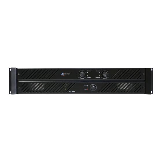
Professional Audio Amplifier SY 400 SY 800 SY 1200 SY 1600 SY 400V SY 800V SY 6125 SY 4200 Operation Manual... -
Page 2: Safety Precautions
If you are in need of special assistance and the information you require is outside the scope of this !CAUTION! manual, please contact your nearest service agent RISK OF ELECTRICAL SHOCK or Australian Monitor direct: DO NOT OPEN THE TECHNICAL OFFICER AUSTRALIAN MONITOR The presence of an EXCLAMATION MARK... -
Page 3: Protection Features
Input muting at turn-on. Layout, grounding, decoupling and componentry > have been optimized to provide the user with Input overvoltage protection. stability reliability longevity > Radio-frequency interference suppression. > Short-circuit protection and indication. > High overload mains fuse. Australian Monitor... -
Page 4: Table Of Contents
Contents Page Introduction Controls, Connectors and Indicators 2.1 Front Panel 2.2 Rear Panel Installation Operation Maintenance Specification List of Illustrations Page Figure 1. Block Diagram Figure 2. Front Panel Layout(SY6125, SY1200, SY4200) Figure 3. Rear Panel Layout (SY400, SY1600) Figure 4. Rear Panel Layout (SY6125, SY4200, SY400V) Figure 5.Top Lid Layout (SY6125, SY4200) Figure 6. -
Page 5: Introduction
Introduction 5 1. Introduction Congratulations on choosing Australian Monitor for Each channel of the amplifier comprises a balanced your professional amplification requirements. active input with a buffered attenuator driving a differential class A drive stage which in turn drives a... -
Page 6: Controls, Connectors And Indicators
6 Controls & Connectors 2. Controls, Connectors & Indicators F i g u r e 2 F r o n t P a n e l L a y o u t ( l e ft t o r i g h t - S Y 4 2 0 0 , S Y 1 2 0 0 , SY6125) -
Page 7: Front Panel
(e.g. slate on a mixing will continue to run and once the effected console). The 1 watt level is the mid-point channel/s have had a cool-down period, they will between the indicator illuminating and un-mute and return to normal operation. extinguishing green. Australian Monitor... -
Page 8: Fault Indicator
8 Controls & Connectors NOTE: You should always ensure that the fan grille is kept clean and free from the build up of dust and lint . This will ensure longer operation of your amplifier and reduce the possibility of it prematurely going into thermal shutdown mode. -
Page 9: Figure 3. Rear Panel Layout (Sy400, Sy1600)
Controls & Connectors 9 Figure 3 Rear Panel Layout (left to right - SY400, SY1600) Australian Monitor... -
Page 10: Figure 4. Rear Panel Layout (Sy6125, Sy4200, Sy400V)
10 Controls & Connectors Figure 4 Rear Panel Layout (left to right) - SY400V, SY6125, SY4200... -
Page 11: Rear Panel
A’s input XLRs and the level of one connector for bi-amp applications. Channel- both channels will be controlled by channel A’s Australian Monitor... -
Page 12: Limiter Switch
12 Controls & Connectors attenuator. The output from channel B will itself and shut down. This is worst at lower automatically be of the opposite polarity frequencies. Engaging the limiter helps control (reversed phase) and speaker termination should this problem. be sourced from the red binding-post outputs. -
Page 13: Figure 5.Top Lid Layout (Sy6125, Sy4200)
ON ( ) LIMITER ON ( ) DIP 3 DIP 4 LIMITER FILTER LIMITER ON ( ON ( ON ( DIP 1 DIP 2 DIP 3 DIP 4 Figure 5 Top Lid Layout (top to bottom - SY4200, SY6125) Australian Monitor... -
Page 14: Installation
14 Installation fans to evacuate the heated air and aid the flow of 3. Installation cool air through the unit. Input Wiring Power Requirements IMPORTANT Power consumption for your model of the Synergy Do not directly connect pin 1 on the amplifier’s input Series amplifier is indicated on the rear panel for or strapping XLR, to the amplifier’s chassis, speaker maximum output. -
Page 15: Figure 6. Speaker Connector Wiring
A & channel B outputs (see Figure 6 Speaker Connector Wiring Diagrams). The "Channel B" speaker connector carries the Channel B output only. Figure 6. Speaker Connector This arrangement allows you the option of Wiring Diagram Australian Monitor... -
Page 16: Operation
16 Operation 4. Operation amplifier goes through an initialising period before it will accept signal. The Inrush Current Suppression (ICS) circuit is in operation for the first 0.5 seconds. IMPORTANT This limits the mains current, to prevent "nuisance- All signal source equipment should be tripping"... - Page 17 NOTE: Be wary of quasi-balanced outputs, these input as a signal and is amplified as hum. are often no more than floating unbalanced outputs. There are three things you can do to avoid earth loop problems: Australian Monitor...
-
Page 18: Maintenance
18 Maintenance 5. Maintenance The fan blades are accessible once the lids are removed and can be easily cleaned. You need only hold the fan rotor still and wipe the dust off the blades. Many users stall the fan and use Only competent qualified... - Page 19 Australian Monitor...
-
Page 20: Specification
20 Specifications SY400 SY800 Model: Model: Output Power Output Power Per Channel @ 4 ohms 0.1% THD Per Channel @ 4 ohms 0.1% THD Single channel driven 240W Single channel driven Both channels driven 200W Both channels driven 375W (2 ohm loads not recommended) (2 ohm loads not recommended) Bridge mode Bridge mode... - Page 21 Features of the SY Series Forced air cooled Toroidal mains transformer Equipped with XLR male/female CE Approved (EMC & LVD) inputs Dual output connectors, binding posts and 4 pole speaker connectors GND lift facility Clip limiter circuit provided standard Australian Monitor...
-
Page 22: Output Power
22 Specifications SY6125 SY4200 Model: Model: Output Power Output Power Per Channel @ 4 ohms 0.1% THD Per Channel @ 4 ohms 0.1% THD Single channel driven Single channel driven All channels driven 6 x 125W All channels driven 4 x 200W (2 ohm loads not recommended) Bridge mode Bridge mode... - Page 23 @ 1KHz Rated Power into 50 ohm (-3dB) Rated Power into 25 ohm (-3dB) Dimensions Dimensions H,W,D = (87 x 482x400) mm H,W,D = (87 x 482x400) mm Shipping Weight = 18 Kg Shipping Weight = 22 Kg Australian Monitor...
- Page 24 Australian Monitor www.australianmonitor.com.au Distributed by: Audio Telex Communications Pty Ltd ACN 001345482 www.audiotelex.com.au International Enquiries Ph: 612 9647 1411, Fax: 612 9748 2537, E-mail: international@audiotelex.com.au Sydney Ph: (02) 9647 1411, Fax: (02) 9648 3698, E-mail: nsw@audiotelex.com.au Melbourne Ph: (03) 9890 7477, Fax: (03) 9890 7977, E-mail: vic@audiotelex.com.au Brisbane Ph: (07) 3852 1312, Fax: (07) 3252 1237, E-mail: qld@audiotelex.com.au...
Need help?
Do you have a question about the SY 1200 and is the answer not in the manual?
Questions and answers