AUSTRALIAN MONITOR HS250P Installation And Operational Manual

AUSTRALIAN MONITOR HS250P Installation And Operational Manual

Constant voltage power amplifiers with usb/rs232 control; hsp series

Advertisement

INSTALL ATION AND OPERATION MANUAL
HSP SERIES
CONSTANT VOLTAGE POWER AMPLIFIERS
HS120P
WITH USB/RS232 CONTROL
HS250P
HS2120P
HS2250P
HS4120P
HS4250P

Advertisement

Table of Contents
loading
Need help?

Need help?

Do you have a question about the HS250P and is the answer not in the manual?

Questions and answers

Subscribe to Our Youtube Channel

Summary of Contents for AUSTRALIAN MONITOR HS250P

  • Page 1 INSTALL ATION AND OPERATION MANUAL HSP SERIES CONSTANT VOLTAGE POWER AMPLIFIERS HS120P WITH USB/RS232 CONTROL HS250P HS2120P HS2250P HS4120P HS4250P...
  • Page 2: Important Safety Information

    IMPORTANT SAFETY INFORMATION PRÉCAUTIONS DURANT UTILISATION LISEZ ces instructions. Read these instructions. Tenez ces instructions. Keep these instructions. Notez tous les avertissements. Heed all warnings. Suivez toutes les avertissements. Follow all instructions. N’utilisez pas ce produit près de l’eau (la piscine, la plage, le lac, etc.). Do not use this apparatus near water.
  • Page 3: Introduction And Contents

    INTRODUCTION AND CONTENTS Introduction HSP SERIES Features & Protection Features Congratulations on choosing Australian Monitor for your professional 
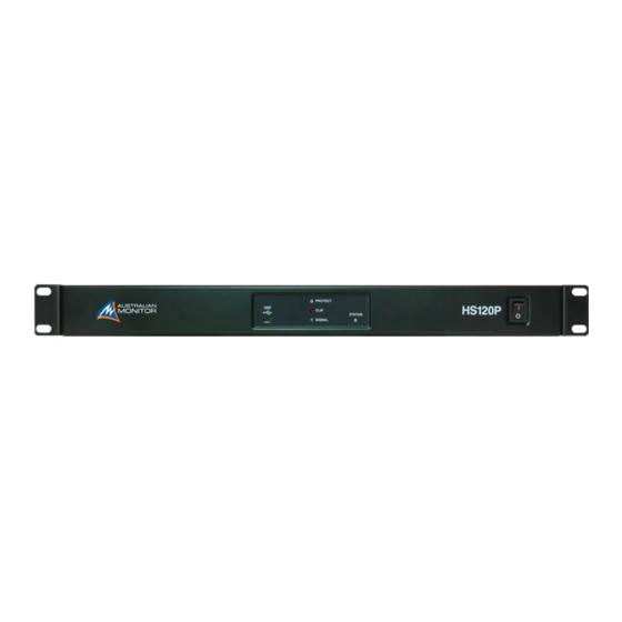
Controls, Connectors and Indicators amplification requirements. Software Setup The design of our HSP series constant voltage power amplifiers embraces all the aspects of a well-designed amplifier. The visual...
  • Page 4: Protection Features

    FEATURES & PROTECTION FEATURES FEATURES Single Channel - HS120P- 1 x 120W, HS250P – 1 x 250W PC controlled software graphical user interface control • • • Dual Channel - HS2120P – 2 x120W, HS2250P - 2x250W • USB and RS232 interface for DSP configuration and overall product control Quad Channel - HS4120P –...
  • Page 5: Controls, Connectors And Indicators

    Plug in the supplied USB Type A to Mini Type B connector into this port to communicate with the amplifier from the PC software application. The PC software application, downloadable from the Australian Monitor website, allows for real time monitoring of the amplifier inputs and outputs. The PC software application is also used to configure the DSP functionality to cater for the installation environment.
  • Page 6: Rear Panel

    CONTROLS, CONNECTORS & INDICATORS HSP 1 Channel 1RU rear panel shown above HSP 4 Channel 2RU rear panel shown above REAR PANEL Mains Input Connector External Mute, Standby and Fault Your amplifier is fitted with a standard IEC 60320-C14 socket for mains External Mute connection.
  • Page 7: Audio Source

    CONTROLS, CONNECTORS & INDICATORS Input Signal Attenuation Pot Phoenix Balanced Input The fully clockwise position (when viewed from rear) of the input signal A balanced male 3-pin (3.81mm) Phoenix type connector is provided attenuation pot provides no attenuation (ie 0 dB). Turning the pot counter on each input channel.
  • Page 8: Software Setup

    SOFTWARE SETUP Supported Operating Systems Software Control Over RS232 • Windows 10 The RS232 control port works in two ways Windows 8 As an alternative control port to the front panel USB for longer • distance control using the PC application. Windows 7 (32/64 bit) •...
  • Page 9 SOFTWARE SETUP (CONT) RS232 using the PC application Most modern PC’s require a USB to RS232 converter for RS232 operation. Upon successful connection the main application window will look like the A suggested RS232 to USB converter is the FTDI (USB-RS232-WE-1800- image below (Note: The number of channels displayed will depend on the BT_5.0) which can be sourced through most online electronic component HSP model):...
  • Page 10 SOFTWARE SETUP (CONT) Software Developer Mode A highly recommended method to easily understand the commands being Select the “Developer” mode button shown below sent and received by the amplifier is to turn on “Developer” mode on the PC application. This will open a second window that displays the commands being sent and received when the user interacts with the PC application.
  • Page 11: Password Protection

    SOFTWARE SETUP (CONT) External Mute The external mute functionality is activated using the supplied 4-way Phoenix connector. Simply connect the MUTE to GND to mute channels of the amplifier. See connection diagram listed below for a simple connection: The PC application includes toggle buttons to select which amplifier channels are muted using the external mute trigger. Select or deselect the channels required in the application.
  • Page 12 SOFTWARE SETUP (CONT) Priority 1 – External Input Priority 2 – Command Interface The standby function is activated using the supplied 4-way Phoenix connector. Send the following command using RS232 Simply connect the STANDBY to GND to put the amplifier into standby mode. To enter standby: set device mode standby true See connection diagram listed below:...
  • Page 13: Installation

    Pin 1 = Hot (non-inverting or in phase) The HS250P, HS2120P, HS2250P, HS4120P and HS4250P amplifiers are Pin 2 = Cold (inverting or reverse phase) cooled by axial fans which draw air inside the amplifier and expel the heated air outside the amplifier.
  • Page 14: Installation (Cont)

    INSTALLATION (CONT) Speaker Outputs The amplifier output has a 6 pin output screw terminal with a pre-fitted link between the 4Ohm and the high impedance output. Fit the link between 4Ω and the OT-IN. (This connects the amplifier output to the input of the 70/100V transformer) •...
  • Page 15: Hum Problems

    INSTALLATION (CONT) Hum Problems Most equipment is designed for minimum hum when used under ideal lead or a speaker lead. The problem can usually be reduced by moving the conditions. When connected to other equipment, and to a safety earth in an offending lead away, or by providing additional electrostatic shielding (i.e.
  • Page 16: Basic Setup & Operation

    BASIC SETUP & OPERATION Fault Finding Status Indicator If the blue STATUS LED is flashing instead of remaining on then a specific system state is being displayed. See the table below on the meaning and of the system state. The status LED should indicate the following: Meaning Indication Blue On...
  • Page 17: Maintenance

    MAINTENANCE & FIRE REGULATION COMPLIANCE Maintenance • Only competent or qualified persons should attempt any service or maintenance of your amplifier. Your HSP amplifier will need minimal maintenance. • No internal adjustments need to be made to the unit to maintain optimum performance. •...
  • Page 18: Specifications

    SPECIFICATIONS HS120P HS250P HS2120P HS2250P HS4120P HS4250P Model Conditions/Comments Topology Class-D Class-D Class-D Class-D Class-D Class-D   Channels   Power Output (per channel) 4Ω 136W 260W 136W 259W 135W 242W 1kHz. 1%THD. -10W/+30W, CEA-2006, one channel driven 124W 244W 124W...
  • Page 19: Specifications (Cont)

    SPECIFICATIONS (CONT) HS120P HS250P HS2120P HS2250P HS4120P HS4250P Model Conditions/Comments Input/Outputs  Audio Input Balanced Phoenix Input per channel  Data/Control USB Mini Type B. RS232 (TX,RX,GND). 3 pin 3.81mm Euroblock connector. Logic (Fault, Mute, Standby, GND). 4 pin 3.81mm Euroblock connector.
  • Page 20 589W 554W 896W 230Vac, 50Hz, 100V Output, 1kHz, Sine HS120P = 1 x 115W, HS250P = 1 x 217W, HS2120P = 2 x 120W, HS2250P = 2 x 192W, HS4120P = 4 x 90W, HS4250P = 4 x 150W Efficiency...
  • Page 21 SPECIFICATIONS (CONT) HS120P HS250P HS2120P HS2250P HS4120P HS4250P Model Conditions/Comments Weights & Dimensions Product Dimensions 483mm x 325mm x 44.5mm   W x D x H (with rack ears) (19.0” x 12.8” x 1.75”) Product Dimensions 435mm x 325mm x 44.5mm 435mm x 389mm x 89mm  ...
  • Page 22: Serial Command Protocol

    Operation is “get”, “set” or “reply” • Supported content for section, group, param, sub, ssub and value message fields are as per the Australian Monitor Interface Protocol Specification. • Message fields operation, section, group & param are mandatory, sub & ssub fields are optional.
  • Page 23 SERIAL COMMAND PROTOCOL HSP SERIES INSTALLATION AND OPERATION MANUAL PAGE 23...
  • Page 24 SERIAL COMMAND PROTOCOL (CONT) PAGE 24 HSP SERIES INSTALLATION AND OPERATION MANUAL...
  • Page 25 SERIAL COMMAND PROTOCOL (CONT) HSP SERIES INSTALLATION AND OPERATION MANUAL PAGE 25...
  • Page 26 SERIAL COMMAND PROTOCOL (CONT) PAGE 26 HSP SERIES INSTALLATION AND OPERATION MANUAL...
  • Page 27 NOTES HSP SERIES INSTALLATION AND OPERATION MANUAL PAGE 27...
  • Page 28 ENGINEERED BY AUSTRALIAN MONITOR Address: 1 Clyde St, Silverwater NSW 2128 Australia. Website: www.australianmonitor.com.au International enquiries email: international@australianmonitor.com.au ABN 35 007 573 417...

This manual is also suitable for:

Hs120pHs4120pHs4250pHs2120pHs2250pHsp series

Table of Contents