
Related Manuals for Rigol PCA1500


Summary of Contents for Rigol PCA1500
- Page 1 RIGOL 用户手册 PCA1030/PCA2030/PCA1150 /PCA1500 电流探头 2022 年 5 月 RIGOL TECHNOLOGIES CO., LTD.
- Page 3 商标信息 RIGOL 是普源精电科技股份有限公司的注册商标。 文档编号 UGE32001-1110 声明 本公司产品受中国及其它国家和地区的专利(包括已取得的和正在申请的 专利)保护。 本公司保留改变规格及价格的权利。 本手册提供的信息取代以往出版的所有资料。 本手册提供的信息如有变更,恕不另行通知。 对于本手册可能包含的错误,或因手册所提供的信息及演绎的功能以及因 使用本手册而导致的任何偶然或继发的损失,RIGOL 概不负责。 未经 RIGOL 事先书面许可,不得影印、复制或改编本手册的任何部分。 产品认证 RIGOL 认证本产品符合中国国家产品标准和行业产品标准及 ISO9001:2015 标 准和 ISO14001:2015 标准,并进一步认证本产品符合其它国际标准组织成员的 相关标准。 联系我们 如您在使用此产品或本手册的过程中有任何问题或需求,可与 RIGOL 联系: 电子邮箱:service@rigol.com 网址:www.rigol.com PCA1030/PCA2030/PCA1150/PCA1500 用户手册...
-
Page 4: 一般安全概要
RIGOL 一般安全概要 注意 本产品符合 IEC 61010 安全标准并在出厂前经过安全测试。 但使用中的任何不当 操作都可能会对操作人员造成伤害甚至危及生命安全,也会对设备造成损坏。因 此,使用本产品之前,请确保理解本手册所述的指导说明和注意事项。 安全术语和符号 使用本产品之前,请仔细阅读如下安全注意事项。 产品上的 符号表示用户在使用相关功能之前须阅读手册中标 有 符号的内容。 手册中的 符号表示重要信息,用户须阅读该内容后才可使用 产品。 产品上的 符号表示仅可测量符合被测电路电压的绝缘导体。 本手册中如下符号表示重要的注意事项或警告信息。 表示不正确的操作将导致极端危害,对操作者造成严重伤害或死 危险 亡。 表示不正确的操作将导致重大危害,对操作者造成严重伤害或死 警告 亡。 表示不正确的操作可能对操作者造成伤害或损坏设备。 注意 备注 表示与设备性能或正确操作相关的建议。 PCA1030/PCA2030/PCA1150/PCA1500 用户手册... -
Page 5: Table Of Contents
保证和声明 ....................I 一般安全概要 ..................II 安全术语和符号 ..................II 安全注意事项 ..................IV 服务....................VII 电流探头简介 ..................1 PCA1030/PCA2030 部件总览 ............... 2 PCA1150/PCA1500 部件总览 ............... 3 部件说明................... 3 电流探头使用方法 ..................5 测量准备................... 5 消磁和零位调整 ................. 5 测量步骤................... 6 测量过程中需要注意的事项 .............. 10 规格...................... -
Page 6: 安全注意事项
RIGOL 安全注意事项 危险 请勿在裸导体附近测量,否则可能会引起短路或遭受电击。只可在对电路 电压提供充分绝缘的导线处进行测量。 测量含有高频成分的电流时,请参考附录2 最大输入电流与频率的关系。 请勿测量超过额定值的电流。 在高频或强磁环境下使用本产品可能导致产品出现异常发热,进而引起火 灾、设备损坏或烧坏(见规格)。 为避免电击或短路,请遵守如下注意事项。 首先将探头与波形测量仪器连接,然后再将该探头连接至被测的有源 电线。 打开传感器时,请勿将被测导体短接。 测量时,请勿损坏仪器的绝缘层。 为避免电击,连接被测导体前,请确保其绝缘层完好无损。连接时, 请注意不要损坏被测导体的绝缘层。 为避免发生火灾,损坏或烧坏被测对象和设备,测量高频电流或含有 高频成分的电流时请关注如下内容: 涡流损耗可能导致传感器头发热。 介电加热可能导致电缆绝缘层或其它材料发热。 本探头只可连接至断路器的二次侧。此时,断路器可以避免因短路造 成的危害。请勿将本探头连接至断路器的一次侧。此种情况下,短路 时无限制的电流将引起严重事故。 对于与本探头连接的波形测量仪器或其它测量仪器,请确保遵守其所 有操作注意事项。 当测量仪器的输入端口、机箱或其它输入端之间没有绝缘时,请注意 以下几点:如下页图所示,如果信号连接到除本探头所连接的端口之 外的其它输入端口上,请勿将该信号的接地端连接至任何非地电势, 否则短路电流将从接地端流经电流探头,引起电气事故或损坏电流探 头。 PCA1030/PCA2030/PCA1150/PCA1500 用户手册... - Page 7 RIGOL × PCA1030/PCA2030 × PCA1150/PCA1500 警告 请保持仪器干燥,并在测量时保持双手干燥,以免发生电击。 当探头已连接被测导体时,请勿在波形测量仪器上执行消磁操作。否则, 可能损坏电路或引起电气事故,进而造成人身伤亡。 确保输入不要超过最大额定电流,以免由于过热而造成设备损坏、短路进 而发生触电危险。 测量带电线路时,为防止触电,请穿戴合适的防护装备,如绝缘手套、长 靴和安全帽等。 PCA1030/PCA2030/PCA1150/PCA1500 用户手册...
- Page 8 RIGOL 注意 为防止损坏探头,在运输和搬运过程中请注意防震和碰撞,特别要避免跌 落。 本探头仅可在室内安装、操作,温度范围在0℃至40℃,相对湿度不大于 80%。 保存或使用仪器时,请勿将仪器放置在阳光直射、高温、潮湿或容易发生 冷凝的地方,否则,仪器的绝缘性可能会降低从而影响其性能指标,甚至 损坏仪器。 本仪器并非完全防水或防尘,因此,请勿在潮湿或多尘的环境下使用,以 免损坏仪器。 电流传感器头为精密组合件,包含一个模制元件、铁氧体磁芯和霍尔效应 元件。当环境温度突变、受到机械拉力或撞击时,电流传感器可能会损坏。 因此使用时需格外小心。 电流传感器头的齿合面经过了精细的研磨,使用仪器时应格外小心,以免 划伤齿合面,影响探头的性能。 当电流传感器头的齿合面上落有灰尘时,可能会影响测量结果的准确性。 因此,用户需使用干净的软布轻轻擦拭以保持齿合面的清洁。 当电流传感器头的齿合面上落有异物时,可能会产生共振噪音(参考后文 关于共振噪音的介绍)并影响测量结果的准确性。因此,用户需使用干净 的软布轻轻擦拭以保持齿合面的清洁。 请不要过度弯折或拉扯电流传感器电缆,以免损坏电缆。 10. 请勿将静电或其它高压源应用于传感器。否则,可能损坏内部霍尔元件和 电路。 11. 清洁探头时,请使用软布蘸取水或温和溶剂轻轻擦拭。请勿使用苯、酒精、 丙酮、乙醚、酮、稀释剂或汽油等溶剂擦拭。否则,将造成产品变形或褪 色。 12. 接通电源后,除非连接被测导体,其它时间请保持传感器闭合,否则,磁 芯部分的齿合面可能会被划伤。 PCA1030/PCA2030/PCA1150/PCA1500 用户手册...
- Page 9 RIGOL 13. 不使用时请闭合传感器头,以免灰尘堆积到齿合面而影响其夹固性能。 14. 请勿踩踏或挤压电缆,以免损坏电缆的绝缘性。 15. 电缆应远离热源,否则其绝缘层将融化,从而造成导线裸露。 备注 当仪器周围存在强磁场(如变压器和高电流导体附近)或强电磁场(如无线电发 射机附近)时,测量结果可能不正确。 服务 如需返厂维修,请将探头仔细包装以免其在运输过程中发生破损。包装时,请使 用减震材料将探头稳固在包装内。同时,请附上产品故障的详细说明。因运输造 成探头损坏,RIGOL公司恕不负责。 为了保证电流探头可提供指定精度的正确测量结果, 请定期校准探头。 如需校准, 请与RIGOL联系。 PCA1030/PCA2030/PCA1150/PCA1500 用户手册...
-
Page 11: 电流探头简介
RIGOL 电流探头简介 本电流探头直接与波形测量仪器的 BNC 输入连接器相连,通过传感器头连接被 测导体,可轻松捕获电流波形。 主要特色: 高精度电流检测 简捷的电流测量 宽带频率特点 PCA1030:DC 至 50MHz PCA2030:DC 至 100MHz PCA1150:DC 至 10MHz PCA1500:DC 至 2MHz PCA1030/PCA2030:设计紧凑,允许测量小电流 PCA1150/PCA1500:导体直径较大允许测量大电流 简便的超量程输入保护功能 独创的薄膜霍尔效应元件 PCA1030/PCA2030/PCA1150/PCA1500 用户手册... -
Page 12: Pca1030/Pca2030 部件总览
RIGOL PCA1030/PCA2030 部件总览 电流方向标识 传感器 终端连接器 "UNLOCK"标识 传感器电缆 图 1 PCA1030/PCA2030 部件示意图 关于上图中的部件 1 至 4,请参考部件说明。 备注 上图中的终端连接器集成电源,将输出连接器连接至波形测量仪器,当波形测量 仪器上电时,为电流探头供电。 PCA1030/PCA2030/PCA1150/PCA1500 用户手册... -
Page 13: Pca1150/Pca1500 部件总览
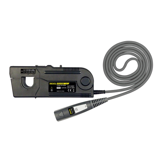
RIGOL PCA1150/PCA1500 部件总览 终端连接器 "LOCK"标识 电流方向标识 传感器 传感器电缆 "UNLOCK"标识 图 2 PCA1150/PCA1500 部件示意图 关于上图中的部件(1、2、4),请参考部件说明。 备注 上图中的终端连接器集成电源,将输出连接器连接至波形测量仪器,当波形测量 仪器上电时,为电流探头供电。 部件说明 滑动开关 用于打开和锁紧电流传感器。测量被测导体时应锁紧电流传感器,以免发 生危险。 对于 PCA1030/PCA2030,滑动开关的一侧标有 OPEN、FREE 和 LOCK 三种 标识,电流传感器的开关状态与滑动开关所处的位置有关: PCA1030/PCA2030/PCA1150/PCA1500 用户手册... - Page 14 RIGOL 当滑动开关处于 OPEN 位置时,电流传感器完全打开,此时可将被测 导体连接至电流传感器; 当滑动开关处于 FREE 位置时,电流传感器处于闭合状态但未锁紧; 当滑动开关处于 LOCK 位置时,电流传感器头处于锁紧状态,此时, UNLOCK 标识被遮挡。 对于 PCA1150/PCA1500,滑动开关上面标有 LOCK 和 UNLOCK 标识,当开 关上面显示 LOCK 标识并且 UNLOCK 标识消失时,电流传感器处于锁紧状 态。 电流传感器头 用于连接被测导体以执行实际电流测量。电流传感器头为精密装置,包含 一个模制元件、铁氧体磁芯和霍尔效应元件。当环境温度突变、受到机械 拉力或撞击时,可能会损坏电流传感器,因此使用时需格外小心。 粗调调整器(仅适用于 PCA1030/PCA2030) 仅当无法在波形测量仪器的零位调整范围内进行调节时使用。可以使用绝 缘螺丝刀(如陶瓷螺丝刀)通过该调整器进行调节。 输出连接器 被测导体的电流波形将以恒定的增益通过该连接器输出至波形测量仪器。 该输出连接器可连接至波形测量仪器的 BNC 输入连接器。...
-
Page 15: 电流探头使用方法
RIGOL 电流探头使用方法 使用电流探头执行测量之前,请仔细阅读安全注意事项一节。 测量准备 准备一台波形测量仪器。 将波形测量仪器连接至交流电源。 将电流探头的输出连接器连接至波形测量仪器的输入端。 打开波形测量仪器的开关,并检查电源指示灯是否点亮。 打开电流探头后,请等待至少30分钟。刚接通电源时,由于预热等因素, 将产生明显的零点漂移,因此,为保证测量的准确性,执行测量前,应将 电流探头预热30分钟以上。 消磁和零位调整 如果波形测量仪器的输入为地电平,应将其基线调整至零位。 将波形测量仪器的输入耦合设置为直流。 注意 断开输出连接器与波形测量仪器的连接时,首先解除锁紧,然后将连 接器拔出。未解除锁紧而直接拔出或拉扯电缆线可能损坏终端连接 器。 若使用 BNC 转香蕉插头或其它类似连接器连接除 BNC 连接器之外的 PCA1030/PCA2030/PCA1150/PCA1500 用户手册... -
Page 16: 测量步骤
RIGOL 输入端,请注意保证极性正确。 当电流探头的电流传感器连接被测导体时,请勿进行消磁操作,因为 消磁操作会导致电流流入导体,可能会损坏被测电路的器件。 鉴于上述考虑,由于为电流探头供电将产生消磁波形,因此为电流探 头供电前,请确保电流探头未连接被测导体。 请确保电流传感器处于锁紧状态(对于 PCA1030/PCA2030,滑动开关应处 于 LOCK 位置;对于 PCA1150/PCA1500,滑动开关上面显示 LOCK 标识且 无 UNLOCK 标识显示)。 在波形测量仪器上执行消磁操作。 在波形测量仪器上执行零位调整操作,将基线调至零位。 备注 对于 PCA1030/PCA2030,当通过波形测量仪器的零位调整功能无法实现零 位调整时,可以通过粗调调整器将基线调整至波形测量仪器的零位调整功 能可调节的范围内。 调整粗调调整器时,请勿用力过大,否则,可能导致调整器脱落。请使用 符合如下要求的一字螺丝刀:螺丝刀头由陶瓷等非导电物质制成,厚 0.4mm,宽 1.8mm,长度不小于 10mm。 测量步骤 检查并确保测量系统安全且上述准备工作已就绪。 PCA1030/PCA2030/PCA1150/PCA1500 用户手册... - Page 17 RIGOL 按照下图箭头所示方向拨动滑动开关打开电流传感器(对于 PCA1030/PCA2030,滑动开关处于 OPEN 位置;对于 PCA1150/PCA1500, 滑动开关上面显示 UNLOCK 标识,LOCK 标识消失)。 滑动开关 调整电流传感器,使其电流方向标识与待测导体中的电流方向一致,使用 电流传感器连接待测导体,并使待测导体位于孔中心。 按照下图箭头所示方向拨动滑动开关将电流传感器锁紧(对于 PCA1030/PCA2030, 滑动开关应处于 LOCK 位置; 对于 PCA1150/PCA1500, 拨动滑动开关直至上面显示 LOCK 标识,UNLOCK 标识消失)。 滑动开关 此时,您可以查看电流波形。PCA1030/PCA2030 的输出增益为 0.1V/A, PCA1150/PCA1500 的增益为 0.01V/A。您可以通过波形测量仪器的电压灵 敏度计算出电流灵敏度。例如,对于 PCA1030,波形测量仪器的电压灵敏 度为 10mV/div,则电流灵敏度为(10mV/div)/(0.1V/A)=100mA/div。 备注 电流探头的电流消耗取决于被测电流。下图为输出电流与电流消耗之 间的关系曲线: PCA1030/PCA2030/PCA1150/PCA1500 用户手册...
- Page 18 RIGOL PCA1030 PCA2030 PCA1030/PCA2030/PCA1150/PCA1500 用户手册...
- Page 19 RIGOL PCA1150 PCA1500 注:电流消耗为正负电流消耗代数和。 PCA1030/PCA2030/PCA1150/PCA1500 用户手册...
-
Page 20: 测量过程中需要注意的事项
RIGOL 测量过程中需要注意的事项 注意 最大连续输入范围是基于测量过程中仪器内部所产生的热量而定的。注意: 输入电流不可超过该范围,否则可能损坏电流探头。 参考附录 2 最大输入电流与频率的关系。最大额定电流为标准条件下正弦 波输入时的推荐值。当环境温度增加或被测电流含有其它频率成分时将增 加自发热。因此,即使电流探头工作在低于额定电流的条件下,也可能由 于自发热而损坏。 如果输入电流超出最大连续输入范围,可能导致仪器内部温度过高而启动 内置的保护电路功能,该功能会阻碍正常的输出。此时,请立即断开电流 传感器与被测导体的连接或将输入电流降低至 0,待电流传感器充分冷却 后,方可重新进行操作。 测量 1kHz 以上(含)的电流将导致电流传感器头温度上升。发生此现象是 因为传感头的自发热。在这种情况下,内置的保护电路功能不会被激活。 请注意避免事故发生,如灼伤、短路及设备损坏。 即使输入电流未超出额定连续输入范围,但长时间的连续输入也会启动保 护电路功能以避免电流传感器发热引起的设备损坏。 当环境温度过高时,即使输入电流低于额定连续输入范围,也可能会启动 内置的保护电路功能。 如果输入电流多次超出额定最大连续输入范围而使保护电路反复启动,将 会造成设备损坏。 最大输入范围由最大连续输入范围确定,也由最大峰值电流值确定。请确 保输入不大于最大连续输入有效值范围。 由于周围导体中的电流可能会使电流传感器温度升高,因此,请勿将带有 10kHz 或更高频率电流的导体放在电流传感器头周围,以免损坏电流传感 器,如下图所示。 PCA1030/PCA2030/PCA1150/PCA1500 用户手册... - Page 21 RIGOL PCA1030/PCA2030 PCA1150/PCA1500 10. 请使用滑动开关打开电流传感器头。对于 PCA1030/PCA2030,传感头锁紧 时,如果其上芯被强制打开,则有可能损坏滑动开关的内部结构。 上芯 备注 刚接通电源时,由于自发热,将产生明显的零点漂移,因此,为防止这种 情况的发生,进行测量前,应将电流探头预热 30 分钟以上。 执行连续测量时,请注意由于环境温度等因素而引起的零点漂移。 在某些情况下,将输出连接器连接至通电的波形测量仪器时,可能会产生 震荡,该情况不属于仪器故障,可通过开关传感器的卡钳消除震荡并使操 作恢复正常。 基于被测电流的幅值和频率,传感器头可能会产生共振噪音。消磁过程中 也可能产生共振噪音。这不属于仪器故障。 若电流传感器头的齿合面沾有异物,这将在电流传感器的上层和下层之间 产生微小缝隙,这种情况下,电流传感器头将产生共振噪音。因此,请在 测量之前使用本手册所述清洁方法清除齿合面上的所有异物。 使用过程中,若共振噪音的音量增大,表示电流传感器的上层和下层之间 的缝隙变大。因此,电流传感器的特性将改变。此时,建议您校准探头。 在波形测量仪器上执行消磁操作,将从探头输出一个消磁波形。该波形可 能并不以零电压线对称,该情况不属于仪器故障。 请将被测导体连接至电流传感器的钳孔中心,否则,将影响测试结果。 PCA1030/PCA2030/PCA1150/PCA1500 用户手册...
- Page 22 RIGOL 执行电流测量时,请确保传感器头已锁紧(对于 PCA1030/PCA2030,滑动 开关应处于 LOCK 位置;对于 PCA1150/PCA1500,首先应该上下按压电流 探头闭合电流传感器,然后拨动滑动开关直至上面显示 LOCK 标识, UNLOCK 标识消失)。若电流传感器没有完全闭合,将无法得到准确的测 量结果。 10. 当仪器周围存在强磁场(如变压器和高电流导体附近)或强电磁场(如无 线电发射机附近)时,测量结果可能不正确。 11. 频率较高时,共模噪声可能会影响电路高压端的测量。此情况下,降低波形 测量仪器的频率范围或连接电路的低压端。 × 高 高 × 信号源 信号源 负载 负载 √ √ 低 低 PCA1030/PCA2030 PCA1150/PCA1500 PCA1030/PCA2030/PCA1150/PCA1500 用户手册...
-
Page 23: Pca1030/Pca2030
-10℃至 50℃,相对湿度≤80%(无凝结) 储存温度和湿度范围 室内,海拔≤2000m,污染等级 2 应用场所 PCA1030:≤20mA(DC 和 60Hz,400A/m 磁场) 外部磁场影响 PCA2030:≤5mA(DC 和 60Hz,400A/m 磁场) 可测量导体的直径 可测量导体 绝缘导体 1 年(开/关次数最多可达 1 万次) 精度保证期 传感器电缆:约 1.5m 电缆长度 传感器: 约 175W×18H×40Dmm (不包括突出部分) 外部尺寸 终端连接器:约 27H×55W×18Dmm PCA1030:约 230g 重量 PCA2030:约 240g PCA1030/PCA2030/PCA1150/PCA1500 用户手册... -
Page 24: Pca1150
1 年(开/关次数最多可达 1 万次) 精度保证期 ≤150mA(DC 或 60Hz,400A/m 磁场) 外部磁场影响 20mm 可测量导体直径 可测量导体 绝缘导体 传感器电缆:约 2m 电缆长度 传感器:约 176W X 69H X 27Dmm 外部尺寸 终端连接器:约 27H X 55W X 18Dmm 约 500g 重量 附件 用户手册,探头包 EN61010 安规 EN61326 PCA1030/PCA2030/PCA1150/PCA1500 用户手册... -
Page 25: Pca1500
最大连续输入范围 (PCA1500) 700A 峰值,非连续 最大峰值电流值 0.01V/A 增益 ±1.0%rdg±5mV,≤500Arms 幅度精度 ±2.0%rdg,≤700A 峰值(DC,45Hz 至 66Hz) ≤25mArms(带宽为 20MHz 的波形测量仪器) 噪声 参考附录 3 输入阻抗(典型)(PCA1500) 输入阻抗 ≤±2% (温度范围 0℃至 40℃, 输入 50Hz, 500Arms) 灵敏度的温度系数 7.2VA(在最大连续输入范围内) 最大额定功率 0℃至 40℃,相对湿度≤80%(无凝结) 操作温度和湿度范围 -10℃至 50℃,相对湿度≤80%(无凝结) 储存温度和湿度范围 室内,海拔≤2000m,污染等级 2 应用场所... -
Page 26: 附录 1 幅频特性
RIGOL 附录 附录 1 幅频特性 PCA1030 PCA2030 PCA1030/PCA2030/PCA1150/PCA1500 用户手册... - Page 27 RIGOL PCA1150 PCA1500 PCA1030/PCA2030/PCA1150/PCA1500 用户手册...
-
Page 28: 附录 2 最大输入电流与频率的关系
RIGOL 附录 2 最大输入电流与频率的关系 PCA1030 PCA2030 PCA1030/PCA2030/PCA1150/PCA1500 用户手册... - Page 29 RIGOL PCA1150 PCA1500 PCA1030/PCA2030/PCA1150/PCA1500 用户手册...
-
Page 30: 附录 3 输入阻抗(典型
RIGOL 附录 3 输入阻抗(典型) PCA1030 PCA2030 PCA1030/PCA2030/PCA1150/PCA1500 用户手册... - Page 31 RIGOL PCA1150 PCA1500 PCA1030/PCA2030/PCA1150/PCA1500 用户手册...
- Page 32 RIGOL User Guide PCA1030/PCA2030/PCA1150 /PCA1500 Current Probe May. 2022 RIGOL TECHNOLOGIES CO., LTD.
- Page 34 RIGOL products are covered by P.R.C. and foreign patents, issued and pending. RIGOL reserves the right to modify or change parts of or all the specifications and pricing policies at the company’s sole decision. Information in this publication replaces all previously released materials.
-
Page 35: General Safety Summary
WARNING user. Indicates that incorrect operation presents a possibility CAUTION of injury to the user or damage to the device. Indicates suggestions related to the performance of the NOTE device or correct operation. PCA1030/PCA2030/PCA1150/PCA1500 User Guide... - Page 36 Safety Precautions ................IV Service ..................... VIII Current Probe Overview ............... 1 PCA1030/PCA2030 Parts Overview ............2 PCA1150/PCA1500 Parts Overview ............3 Parts Introductions ................4 To Use the Current Probe ..............5 Preparations for Measurement ............5 Demagnetizing and Zero Adjustment ........... 6 Measurement Procedure ..............
-
Page 37: Safety Precautions
Be sure to observe all operating precautions for the waveform measurement instrument and other measurement instruments to which this device is connected. When using a measurement instrument that does not provide PCA1030/PCA2030/PCA1150/PCA1500 User Guide... - Page 38 Otherwise, short-circuit current will flow through the current probe from the ground terminal, which could cause an electrical accident or damage. × PCA1030/PCA2030 × PCA1150/PCA1500 PCA1030/PCA2030/PCA1150/PCA1500 User Guide...
- Page 39 The gear mating surface of the sensor head are precision ground, and should be treated with care. If the surface is scratched, performance may PCA1030/PCA2030/PCA1150/PCA1500 User Guide...
- Page 40 NOTE Correct measurement may be impossible in the presence of strong magnetic fields, such as near transformers and high-current conductors, or in the presence of strong electromagnetic fields such as near radio transmitters. PCA1030/PCA2030/PCA1150/PCA1500 User Guide...
-
Page 41: Service
Package the device with the cushioning materials to avoid causing damage to the probe. Be sure to attach the detailed failure descriptions about the product. RIGOL shall not be responsible for any damage of the probe that occurs during shipment. -
Page 42: Current Probe Overview
PCA1150: DC to 10 MHz PCA1500: DC to 2 MHz PCA1030/PCA2030: Compact design, available to measure low current level PCA1150/PCA1500: Large diameter allows high-current measurements Easy protect function at excessive input Unique thin film Hall effect element ... -
Page 43: Pca1030/Pca2030 Parts Overview
For the parts from 1 to 4 noted in the above figure, please refer to Parts Introductions. NOTE In the above figure, the Terminator is connected to the waveform measurement instrument via the output connector. The Terminator will provide power to the current probe when the waveform measurement instrument is powered on. PCA1030/PCA2030/PCA1150/PCA1500 User Guide... -
Page 44: Pca1150/Pca1500 Parts Overview
Indication Terminator Sensor Sensor Cable "UNLOCK" Indication Figure 2 PCA1150/PCA1500 Parts For the parts (1, 2, 4) noted in the above figure, please refer to Parts Introductions. NOTE In the above figure, the Terminator is connected to the waveform measurement instrument via the output connector. The Terminator will provide power to the current probe when the waveform measurement instrument is powered on. -
Page 45: Parts Introductions
UNLOCK indication is covered (cannot be seen). For PCA1150/PCA1500, there are LOCK and UNLOCK indications on the opening lever. The current sensor is locked when the LOCK indication is displayed on the opening lever (the UNLOCK indication disappears). -
Page 46: To Use The Current Probe
To ensure the accurate measurement, wait for at least a 30-minute warm-up after turning on the current probe before performing the measurement. PCA1030/PCA2030/PCA1150/PCA1500 User Guide... -
Page 47: Demagnetizing And Zero Adjustment
Make sure the current sensor is locked (for PCA1030/PCA2030, the opening lever should be in the LOCK position; for PCA1150/PCA1500, LOCK should be displayed on the opening lever and UNLOCK should PCA1030/PCA2030/PCA1150/PCA1500 User Guide... -
Page 48: Measurement Procedure
Open the current sensor by pushing the opening lever in the arrow direction shown in the figure below (for PCA1030/PCA2030, the opening lever should be in the OPEN position; for PCA1150/PCA1500, UNLOCK should be displayed on the opening lever and LOCK should disappear). - Page 49 RIGOL lever should be in the LOCK position; for PCA1150/PCA1500, push the opening lever until LOCK is displayed and UNLOCK disappears). Opening Lever It is now possible to monitor the current waveform. The output gain is 0.1 V/A for PCA1030/PCA2030 and 0.01 V/A for PCA1150/PCA1500. The current sensitivity can be derived from the voltage sensitivity of the waveform measurement instrument.
- Page 50 RIGOL PCA2030 PCA1150 PCA1030/PCA2030/PCA1150/PCA1500 User Guide...
-
Page 51: Precautions For Measurement
If this happens, remove the input immediately (remove the sensor from the conductor being measured, or reduce the input current to zero). Wait until the sensor has had sufficient time to cool before resuming operation. PCA1030/PCA2030/PCA1150/PCA1500 User Guide... - Page 52 10. When opening the sensor head of the probe, be sure to operate with the opening lever. For PCA1030/PCA2030, if an upper core is forced to open while the sensor head is locked, the open-close mechanism can be damaged. Upper Core PCA1030/PCA2030/PCA1150/PCA1500 User Guide...
- Page 53 The reading may be affected by the position within the clamp aperture of the conductor being measured. The conductor should be in the center of the clamp aperture. PCA1030/PCA2030/PCA1150/PCA1500 User Guide...
- Page 54 When carrying out measurement, make sure that the sensor head is locked (for PCA1030/PCA2030, the opening lever should be in the LOCK position; for PCA1150/PCA1500, slide the opening lever until the "UNLOCK" indication disappears, and hold it until LOCK appears). If the sensor head is not properly closed, accurate measurement will not be possible.
-
Page 55: Specifications
Power Operating 0°C to 40°C, ≤80% RH (no condensation) Temperature and Humidity Range Storage -10°C to 50°C, ≤80% RH (no condensation) Temperature and Humidity Range Location for Use Indoor, altitude up to 2,000 m, Pollution Degree 2 PCA1030/PCA2030/PCA1150/PCA1500 User Guide... -
Page 56: Pca1150
±1.0%rdg±1 mV, ≤150 A Amplitude ±2.0%rdg, 150 A to 300 A peak (DC, and 45 Hz to Accuracy 66 Hz) ≤25 mArms (for 20 MHz band waveform Noise measurement instrument) Input Impedance Refer to Appendix 3 Input Impedance PCA1030/PCA2030/PCA1150/PCA1500 User Guide... -
Page 57: Pca1500
PCA1500 DC to 2 MHz (-3 dB), refer to Appendix 1 Bandwidth Amplitude-frequency Characteristics (PCA1500) Rise Time ≤175 ns Maximum 500 Arms, refer to Appendix 2 Relation Continuous Input between Max Input Current and Frequency Range (PCA1500) PCA1030/PCA2030/PCA1150/PCA1500 User Guide... - Page 58 Conductor Cable Length Sensor cable: approx. 2 m External Sensor: approx. 176W X 69H X 27D (mm) Dimension Terminator: approx. 27H X 55W X 18D (mm) Approx. 520g Mass Accessories User Guide, Probe Case Safety EN61010 EN61326 PCA1030/PCA2030/PCA1150/PCA1500 User Guide...
-
Page 59: Appendix
RIGOL Appendix Appendix 1 Amplitude-Frequency Characteristics PCA1030 PCA2030 PCA1030/PCA2030/PCA1150/PCA1500 User Guide... - Page 60 RIGOL PCA1150 PCA1500 PCA1030/PCA2030/PCA1150/PCA1500 User Guide...
-
Page 61: Appendix 2 Relation Between Max Input Current And Frequency
RIGOL Appendix 2 Relation between Max Input Current and Frequency PCA1030 PCA2030 PCA1030/PCA2030/PCA1150/PCA1500 User Guide... - Page 62 RIGOL PCA1150 PCA1500 PCA1030/PCA2030/PCA1150/PCA1500 User Guide...
-
Page 63: Appendix 3 Input Impedance (Typical)
RIGOL Appendix 3 Input Impedance (Typical) PCA1030 PCA2030 PCA1030/PCA2030/PCA1150/PCA1500 User Guide... - Page 64 RIGOL PCA1150 PCA1500 PCA1030/PCA2030/PCA1150/PCA1500 User Guide...
Need help?
Do you have a question about the PCA1500 and is the answer not in the manual?
Questions and answers