Rigol DM3058 User Manual
Digital multimeter
Hide thumbs
Also See for DM3058:
- Programming manual (264 pages) ,
- Performance verification manual (27 pages) ,
- Quick manual (23 pages)

Related Manuals for Rigol DM3058


Summary of Contents for Rigol DM3058
- Page 1 User’s Guide RIGOL Publication number: UGC03113-1112 Nov. 2008 DM3058 Digital Multimeter © 2008 RIGOL Technologies, Inc. All Rights Reserved...
- Page 3 2. RIGOL products are protected by patent law in and outside of P.R. China. 3. Information in this publication replaces all previously corresponding material. 4. RIGOL Technologies, Inc. reserves the right to modify or change part of or all the specifications and pricing policies at company’s sole decision.
- Page 4 Do not touch exposed connections and components when power is on. Do Not Operate With Suspected Failures. If suspected damage occurs with the instrument, have it inspected by qualified service personnel before further operations. Keep Well Ventilated. Do Not Operate in Wet/Damp Conditions. User’s Guide for DM3058...
- Page 5 Do Not Operate in an Explosive atmosphere. Keep Product Surfaces Clean and Dry. The disturbance test of all the models meet the P/F values of A in the standard of EN 61326: 1997+A1+A2+A3, but can’t meet the P/F values of B. User’s Guide for DM3058...
- Page 6 Such devices include most small appliances, test equipment, and other devices that plug into a branch outlet or socket. DM3058 may be used to make measurements with the HI and LO inputs connected User’s Guide for DM3058...
- Page 7 (up to 600 VAC), or to the branch outlet itself. However, DM3058 may not be used with its HI and LO inputs connected to mains in permanently installed electrical devices such as the main circuit-breaker panel, sub-panel disconnected boxes, or permanently wired motors.
- Page 8 CAUTION indicates that a potential damage to the instrument or other property might occur. Terms on the Product. These terms may appear in this manual: Protective Hazardous Refer to Chassis Test Earth Voltage Instructions Ground Ground Terminal User’s Guide for DM3058...
- Page 9 Random Sensor measurement function. The DM3058 holds a high-resolution monochrome LCD display system with clear keyboard layout and operation hints to make it easier and agility to use. Besides, it can support multi-interface such as RS-232, USB, LAN and GPIB also for U-disk.
- Page 10 Config by Remote Control System. Configuration clone for backup all the configuration within instrument into other DM3058 via U-disc or Clone. Chinese and English Menu and Help System Online. Provides with Control Software on PC and Edit Software for Random Sensor ...
- Page 11 RIGOL Structure of this Document Chapt 1 Quick Start Guide you to prepare your DM3058 and know about the Front/Real Panel and User interface. Chapt 2 Panel Operation Introduce you how to operate DM3058 via Front Panel. Chapt 3 Application Examples Introduce you how to use strong measurement functions of this instrument easily through examples.
-
Page 12: Table Of Contents
RIGOL Contents DM3058 Digital Multimeter Overview ............VII Chapter 1 Quick Start ................1-1 General Inspection ..................1-2 Handle Adjustment ..................1-3 The Front Panel ..................1-4 The Rear Panel ................... 1-5 User Interface .................... 1-6 Double Display ..................1-6 Single Display .................. - Page 13 Frequency/Period Characteristics ............5-9 Capacitance Characteristics ..............5-10 Measurement Characteristics ..............5-11 Chapter 6 Appendix ................6-1 Appendix A: DM3058 Accessories ..............6-1 Appendix B: Warranty ................. 6-2 Appendix C: General Care and Cleaning ............6-3 User’s Guide for DM3058...
- Page 14 RIGOL Appendix D: Contact RIGOL ................. 6-4 Index ......................1 User’s Guide for DM3058...
-
Page 15: Chapter 1 Quick Start
RIGOL Chapter 1 Quick Start General Inspection Handle Adjustment The Front Panel The Rear Panel User Interface User’s Guide for DM3058... -
Page 16: General Inspection
Representative. If the shipping container is damaged, or the protective material shows signs of stress, notify the carrier as well as your RIGOL sales office. Keep the shipping materials for the carrier’s inspection. RIGOL offices will arrange reparation or replacement at RIGOL’s option without waiting for claim settlement. -
Page 17: Handle Adjustment
RIGOL Handle Adjustment In order to adjust the handle position of DM3058 Digital Multimeter, please grip the handle in both sides and pull it outward. Then, rotate the handle to the desired position as shown in Figure 1-1. Figure 1-2 Adjust Handle... -
Page 18: The Front Panel
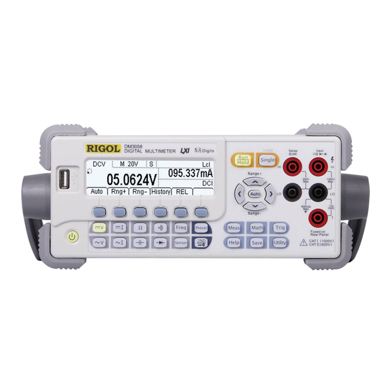
RIGOL The Front Panel It is very important to get familiar with the front panel of a new DM3058. This section gives an introduction of operation and function of the Front Panel. The front panel of the DM3058 (as shown in Figure 1-4) consists of multi-function... -
Page 19: The Rear Panel
RIGOL The Rear Panel Equipped with multifold communication interface for DM3058, it can meet user’s requirements for the interface. Current Input Fuse GPIB 10/100 Power Socket (IEEE--488) Ethernet USB Device Fuse: AC 250V F300mA RS232 RXD LXI Class C Line (20W Max) -
Page 20: User Interface
LXI LXI connection successfully Rmt Remote Control Local Control Main Function Display USB Storage Run Direction Reading Display Vice Display value Vice Display Function Menu Single Display Main Function Display Run Direction Reading Display Figure 1-5 User Interface User’s Guide for DM3058... -
Page 21: Chapter 2 Front Panel Operation
To Control Trigger Options To Set up Measurement Parameters Math Functions To Set Up Trigger Parameters Store and Recall To Set Up the Utility How to Use the Built-in Help System User’s Guide for DM3058... -
Page 22: To Select Range
RIGOL To Select Range For DM3058, appropriate Range could be selected according to the signals input by “Automatic” or “Manual”. In Manual mode, you can obtain higher Reading precision via Range select key on the right side of the Front Panel. Please refer to the following figure. - Page 23 Each press for up key, value will be increased 1, vice versa. At the input interface of data, Left and Right keys are used to switch the number of a numerical value. Each press for Left key, former number will be selected, vice versa. User’s Guide for DM3058...
-
Page 24: To Select Measurement Rate
RIGOL To Select Measurement Rate DM3058 Multimeter provides three types of Measurement Rate: 2.5reading/s, 20reading/s and 120reading/s. 2.5 Reading/s belongs to Slow Rate; the mark of Status Bar is “S” and the rate of refurbishing shows 2.5Hz. 20 Reading/s belongs to Middle Rate, the mark of Status Bar is “M” and the rate of refurbishing shows 20Hz. -
Page 25: Basic Measurement Functions
RIGOL Basic Measurement Functions DM3058 contains following basic functions: To Measure DC Voltage To Measure AC Voltage To Measure DC Current To Measure AC Current To Measure Resistance To Measure Capacitance To Test Continuity ... -
Page 26: To Measure Dc Voltage
RIGOL To Measure DC Voltage DM3058 Multimeter enables to measure DC Voltage up to 1000V. For the details about how to connect and measure please refer to the following steps. Operating Steps: Connecting the red lead (Test leads) to Terminal Input-HI (tested circuit) and black lead to Terminal Input-LO as shown in Figure 2-4. - Page 27 Figure 2-6 View Interface of History data There are three types of way for viewing historical date: “Info”,” List” and HistoG. Press Save after checking, by pressing Update, the History information will be refreshed to be current newest information. User’s Guide for DM3058...
-
Page 28: To Measure Ac Voltage
RIGOL To Measure AC Voltage DM3058 Multimeter enables to measure AC Voltage up to 750V. For the details about how to connect and measure please refer to the following steps. Operating Steps: Connecting the red lead (Test leads) to Terminal Input-HI (tested circuit) and black lead to Terminal Input-LO as shown in Figure 2-7. - Page 29 View interface of history information There are three types of way for viewing historical date: “Info”,” List” and “HistoG”. Press Save after checking. By pressing Update, the History information will be refreshed to be current newest information. User’s Guide for DM3058...
-
Page 30: To Measure Dc Current
RIGOL To Measure DC Current DM3058 Multimeter enables to measure DC Current up to 10A. For the details about how to connect and measure please refer to the following steps. Operating Steps: Connecting the red lead (Test leads) to Terminal Input-HI (tested circuit) and black lead to Terminal Input-LO as shown in Figure 2-11. - Page 31 View Interface of History Information There are three types of way for viewing historical date: “Info”,” List” and “HistoG”. Press Save after checking. By pressing Update, the History information will be refreshed to be current newest information. User’s Guide for DM3058 2-11...
-
Page 32: To Measure Ac Current
RIGOL To Measure AC Current DM3058 Multimeter enables to measure AC Current up to 10A. For the details about how to connect and measure please refer to the following steps. Operating Steps: Connecting the red lead (Test leads) to Terminal Input-HI (tested circuit) and black lead to Terminal Input-LO as shown in Figure2-14. - Page 33 Figure 2-16 View interface of history information There are three types of way for viewing historical date: “Info”,” List” and “HistoG”. Press Save after checking, by pressing Update, the History information will be refreshed to be current newest information. User’s Guide for DM3058 2-13...
-
Page 34: To Measure Resistance
Terminal Input-LO as shown in Figure 2-17. Resistance Figure 2-17 Sketch map for connecting Press and select 2-Wire Resistance Measurement Mode to enter following interface. Figure 2-18 2-Wire Resistance Measurement Interface Choose a proper Resistance range according to its scope. User’s Guide for DM3058 2-14... - Page 35 Press Save after checking, by pressing Update, the History information will be refreshed to be current newest information. NOTE You are suggested to make use of Relative function when measuring small resistance to reduce or escape impedance error from Test leads. User’s Guide for DM3058 2-15...
- Page 36 Test leads to both side of the measured resistance. 4-Wire Sense HI Resistance 4-Wire Sense LO Figure 2-20 Sketch map for connecting Press twice to switch to 4-Wire Resistance Mode. Figure 2-21 Measurement Interface Choose an appropriate resistance range according to its scope. User’s Guide for DM3058 2-16...
- Page 37 Figure 2-22 History Information There are three types of way for viewing historical date: “Info”,” List” and “HistoG”. Press Save after checking. By pressing Update, the History information will be refreshed to be current newest information. User’s Guide for DM3058 2-17...
- Page 38 RIGOL NOTE Please do not put the terminals of the resistance on the electric table or in your hand to avoid error. The smaller of the resistance, the more affection it will be brought. User’s Guide for DM3058 2-18...
-
Page 39: To Measure Capacitance
RIGOL To Measure Capacitance The DM3058 Digital Multimeter has the ability to test Capacitance up to 10000μF. Following practice provides you a guide to get familiar with the Capacitance measurement technique. Operating Steps: Connecting red lead to both Terminal Input-HI and anode of the capacitance and black lead to both Terminal Input-LO and cathode of the capacitance as shown in Figure 2-23. - Page 40 Press Save after checking. By pressing Update, the History information will be refreshed to be current newest information. NOTE Before measuring the electrolytic capacitance, you should make the two legs of the electrolytic capacitance short circuit and let it be discharged. User’s Guide for DM3058 2-20...
-
Page 41: To Test Continuity
When the measured resistance in circuit is lower than selected one, it is considered being connected by instrument. Next, we will introduce you how to test continuity for circuit by using DM3058 step by step to make you familiar with this technique. Operating Steps: Connect test leads as shown in figure 2-26. - Page 42 RIGOL Table 2-8 Continuity Measurement Characteristics Test Current Range 2KΩ immovable Open-circuit Voltage <8V Input Protection 1000V (HI Terminal) 0≤R ≤Short-circuit impedance; testing Beep Condition 1Ω≤Short-circuit impedance≤2kΩ User’s Guide for DM3058 2-22...
-
Page 43: To Check Diodes
When connecting, the instrument will beep one time (If Sound is open, refer to “System Settings”). Table 2-9 Check Diodes Characteristics Test Current Range 2.0V immovable Open-circuit Voltage <8V Input Protection 1000V (HI Terminal) Beep Condition 0.1V≤V ≤2.0V measured User’s Guide for DM3058 2-23... -
Page 44: To Measure Frequency And Period
Connect test leads as shown in figure 2-30. Red test lead connects with Terminal HI; Black test lead connects with Terminal LO. AC Signal Figure 2-30 Sketch map for connecting Press to enter into the following interface. Figure 2-31 Frequency Measurement Interface User’s Guide for DM3058 2-24... - Page 45 Figure 2-32 View interface of History information There are three types of way for viewing historical date: “Info”,” List” and “HistoG”. Press Save after checking. By pressing Update, the History information will be refreshed to be current newest information. User’s Guide for DM3058 2-25...
- Page 46 Set the relative value ( Optional) Press REL to open or close Relative operation function. When it is open, “REL” is shown over the screen and the reading displayed is a relative value which comes User’s Guide for DM3058 2-26...
- Page 47 View Interface of History Information There are three types of way for viewing historical date: “Info”,” List” and “HistoG”. Press Save after checking. By pressing Update, the History information will be refreshed to be current newest information. User’s Guide for DM3058 2-27...
-
Page 48: To Measure Sensor
Sensor is shown on the screen directly and you can edit or modify its display unit at will. DM3058 supports DCV, DCI, and Freq, 2WR, 4WR and Thermocouple TC 6 kinds of Sensor in all. Meanwhile, there are 10 groups of basic Sensor preset within the instrument. - Page 49 Figure 2-36 Sketch map for connecting As the Current Sensor, please connect the red lead (Test leads) to Terminal Input-HI (the jack marked “I”) and black lead to Terminal Input-LO as shown in Figure2-37. Sensor Figure 2-37 Current Sensor Connecting User’s Guide for DM3058 2-29...
- Page 50 CodeT Set the display mode for measurement parameters of Random Sensor. Press New to create a new Sensor. Figure 2-39 New interface (1) Press Prpty to enter into the input interface Figure 2-40 Property Interface User’s Guide for DM3058 2-30...
- Page 51 Figure 2-42 Type selection interface Press Unit button to select the unit for measured physical quantity, for example: ℃, Pa, %, °, and F. Furthermore, you can define required unit by USER function. Figure 2-43 Unit selection interface User’s Guide for DM3058 2-31...
- Page 52 The arithmetic of first data sect is default as “Line” which can be modified by clicking Edit. Incept symbol Arithmetic of current data Figure 2-46 View interface of Reference data User’s Guide for DM3058 2-32...
- Page 53 Figure 2-50 Save Interface Then, Press and go bake to New Interface. Press Apply as shown in figure 2-48 and load settings into current Sensor and use it directly. Figure 2-51 Apply new Sensor User’s Guide for DM3058 2-33...
- Page 54 (For the details about how to set, please refer to” Math” in Chapterer2.) Measurement Value Display. Press Disp, to select showing mode for the measurement result. Figure 2-54 Display mode Figure 2-55 Display the value User’s Guide for DM3058 2-34...
-
Page 55: Preset
RIGOL Preset Preset Mode is provided to avoid error operation via testing product line in DM3058. In random operation mode, please press to enter into following menu. Figure 2-56 Interface of Preset (two pages in all) Ten preset keys existing in Preset Mode and all of them are corresponding with the 10 configuration files in Configuration memorizer respectively. -
Page 56: Secondly Function
If Sensor is used in Main Display, and both of Display has same type, then the result will be shown in Main Display and the measurement value is shown in Vice Display. If different measurement function is used, the results will be shown in corresponding display. User’s Guide for DM3058 2-36... -
Page 57: To Control Trigger Options
Auto trigger is considered as a default when the power is on. Then key will be lightening which indicates this function has been started. Optional trigger modes of DM3058 contain Auto Trigger, Single Trigger and Hold Trigger. Auto Trigger Once you press one time, Auto Trigger will be started to capture continuous readings automatically. -
Page 58: To Set Up Measurement Parameters
Filter, enter the menu shown below. If AC hefts existing in measured DC signal, you can strain them off by AC Filter so as to make the data more exactly. Figure 2-57 Open/Close AC Filter User’s Guide for DM3058 2-38... - Page 59 200mV, 2V and 20V measurement range is >10GΩ; for 200V and 1000V measurement range is kept at 10MΩ. The DC input impedance default is 10 MΩ; settings of DC input impedance are stored in the volatile storage. User’s Guide for DM3058 2-39...
- Page 60 RIGOL Continue Resistance Set up the continue resistance value in the short test menu. When the measured resistance is below P/F, the DM3058 will beep to indicate the circuit continuation. The continue resistance is only using at Continue Test. Press ...
-
Page 61: Math Functions
RIGOL Math Functions The DM3058 provides five math functions: Null, statistic, dB, dBm and P/F testing. Only one of these math functions can be enabled at a time, and remains in effect until change. Press key, the display shows: Measure Current... -
Page 62: Statistic Measurement
(Maximum) Statistical measurement all reading Min value. (Minimum) Statistical measurement all reading Average (Average) value. The complete a set of measurement. Open the selected statistic measurement Save all changes, back to a higher level menu. User’s Guide for DM3058 2-42... -
Page 63: P/F Measurement
Up and Down Directive keys. Unit The unit of P/F is decided by the current measurement function. Over P/F hint When the readings exceed selected upper P/F, the vice-scream will show “HI FAIL” User’s Guide for DM3058 2-43... - Page 64 The upper P/F value should be always bigger than the lower P/F value. The upper and lower values are stored in volatile storage. They will be set to defaults when power on. User’s Guide for DM3058 2-44...
-
Page 65: Dbm Measurement
2Ω ~ 8000Ω. Open dBm Measurement , Status bar shows “dBm”. Save all changes, back to a higher level menu. The computation method of the dBm: dBm = 10 x Log [(Reading ) / 0.001W ] User’s Guide for DM3058 2-45... -
Page 66: Db Measurement
Range of the dB setting value: -120 dBm ~ +120 dBm. The default is 0 dBm. NOTE: You can either let the instrument automatically measure this value, or you can enter a specified value. Settings of dB value are stored in volatile storage. User’s Guide for DM3058 2-46... -
Page 67: Relative Operation
Select Default and Press On/Off to start Null operation, then the readings in current set will be a reference to save for Multimeter and the screen shows 0. Users can input needed preset value by directive keys in the corresponding setting interface. User’s Guide for DM3058 2-47... -
Page 68: To Set Up Trigger Parameters
RIGOL To Set Up Trigger Parameters The optional Trigger methods of DM3058 include Manual Trigger, Single Trigger and Exterior Trigger. The default trigger mode is Auto. Press to capture continuous readings automatically. If you repress it once more, a stable reading will be captured and hold. -
Page 69: Auto Triggering
2. Reading Hold The reading hold mode captures and holds a reading on the front panel display when a stable reading is detected. The system Hold ranges are 0.01%, 0.1%, 1%, and 10%. User’s Guide for DM3058 2-49... - Page 70 Max (Reading, ReadingN-1, ReadingN-2, ReadingN-3) Min (Reading, ReadingN-1, ReadingN-2, ReadingN-3) NOTE: When Reading Hold started, the input resistance was set to 10MΩ for all DC voltage range to reduce noise arising from the open-loop testing. User’s Guide for DM3058 2-50...
-
Page 71: Single Triggering
Sample Count indicates the count of point have been sampled while the instrument get a signal of Single Trigger. The range of sampling point should be between 1 and 1000. The default of Sample Count is 1. User’s Guide for DM3058 2-51... -
Page 72: External Triggering
After setting the parameter, press to go back to last Manu and run External Trigger by pressing Done . Now, on the Front Panel will be crushed out, the instrument enter into the External Trigger Mode. User’s Guide for DM3058 2-52... - Page 73 At external triggering mode, when the data sampling is over, the instrument will output a pulse signal to indicate operation completed. At external triggering mode, when operating math P/Fed value, the instrument will export a pulse signal to indicate out of P/Fs detected. User’s Guide for DM3058 2-53...
-
Page 74: Store And Recall
Choose the type of the files shown. Sensor/ Sensor Data/ MIRR_CFG Read Load the selected file. Save Save the file to the specified location. Erase Delete the selected file. Save all changes, back to a higher level menu. User’s Guide for DM3058 2-54... - Page 75 Use the up and down buttons to select the file, then presses Read, Save and Erase soft keys to do the corresponding operation. Figure 2-75 File operation Interface To save the file, name the file with letters and/or numbers. User’s Guide for DM3058 2-55...
- Page 76 Use the up/down button to close or open the number/letter selection area display. Use the left/right button to move cursor in Filename or number/letter selection area. The Del function can only delete the letter on which the cursor taking place. Press Done to save current file. User’s Guide for DM3058 2-56...
-
Page 77: To Set Up The Utility
Settings Function Menu Menu To choose the commands To set up I/O and LAN parameters. system information System configuration. Test and calibration function. Print Open/Close pint function. Save all the changes to end current operation User’s Guide for DM3058 2-57... -
Page 78: Commands
RIGOL Commands DM3058 compacts three types of commands which are:Rigol DM3058 commands、 Agilent34401A Commands and Fluck45 Commands. Rigol Commands is the default. Press Cmd to enter the following interface to choose needed Commands. Figure 2-78 Selection Interface User’s Guide for DM3058... -
Page 79: I/O Settings
Save all changes, back to a higher level menu. Operation introduction: Remote control through LAN, GPIB (IEEE-488), USB and RS-232 interface can be configured. The I/O interface of GPIB, USB and RS-232 only one could be used at the same time. User’s Guide for DM3058 2-59... - Page 80 Apply Apply current LAN settings. Default Resume default settings. Host Name/ Set the host name. Domain Name/ Set the domain name. DNS address Set DNS address. Save all changes, back to a higher level menu. User’s Guide for DM3058 2-60...
- Page 81 Suggest you ask you network administrator for available subnet mask. Subnet mask can be saved in non-violet memory. Gateway: Suggest you ask you network administrator for an available gateway. Gateway can be saved in non-violet memory. User’s Guide for DM3058 2-61...
- Page 82 0 and 30. The default address is “1” when the instrument is shipped from the factory. Press I/O GPIB, enter the menu shown below: Figure 2-82 GPIB Setting User’s Guide for DM3058 2-62...
- Page 83 115200. The default value is 9600. Parity: Proper configure the parity to make it same as that settled in your computer. There are three parameters: None、 Odd、 Even, the default is “None”. The current choice is stored in nonvolatile storage. User’s Guide for DM3058 2-63...
-
Page 84: System Settings
Format Set up digit display format. Separte PwrOn Set up the power on setting. Default Set up the DM3058 to factory setting. Switch Enable or Disable the front power switch. NOTE: Power on Select the configuration when power on. - Page 85 RIGOL Select languages DM3058 supports two kinds of languages for users. Press Sys Lang, enter the menu shown below: Figure 2-85 choose Language Set Up the Display Press Sys Disp, enter the menu shown below: Figure 2-86 Display settings...
- Page 86 Decimal and Separator cannot be selected as the same format, that is if the Decimal is , then the Separator can only be selected as “No” or “Space”. So there are five different types of way totally to show Number Format by DM3058. User’s Guide for DM3058...
- Page 87 Math Register All registers cleared * dBm Resistance *600Ω Trigger Parameter Factory Defaults Setting Interval 400ms Samples Hold 0.1% Trigger Sources Auto Trigger System Operations Factor Defaults Setting * Sound * Open * Separate * Open User’s Guide for DM3058 2-67...
- Page 88 Interface Factor Defaults Setting * GPIB address * I/O *USB *Baud *9600band *Parity bit * no (8 digits) Calibration Factor Defaults Setting Calibration Stats Password NOTE*: Parameter with (*) are saved in non-volatile Reading Storage User’s Guide for DM3058 2-68...
- Page 89 RIGOL Power Supply Power Supply of DM3058 contains of Real Panel’s switch of Power Supply and software switch that could be set three working mode. Press System Cfg PwrOn to enter into the following interface and select needed Power Supply Mode.
-
Page 90: Test/Cal
Save all the changes and go back to last Manu NOTES: Safety Lock is open before inputting password. After input right password, Safety Lock will be open automatically. The instrument has been adjusted before leaving factory. User’s Guide for DM3058 2-70... -
Page 91: Print
RIGOL Print This function helps users to send out the measure values through RS-232 interface. Press print, enter the following interface: Figure 2-92 Print interface User’s Guide for DM3058 2-71... -
Page 92: How To Use The Built-In Help System
Enter the last page help menu. Enter the next page help menu. Back to a higher level menu. NOTE: The arrowhead are hidden before any operation is token. The method of obtaining the help of the keyword: User’s Guide for DM3058 2-72... - Page 93 Press and hold the key for more than 3 seconds at any operation interface to obtain Help information of the key. To change the electric power fuse How to change the electric power fuse. 10. Technique support Getting the technique support. User’s Guide for DM3058 2-73...
-
Page 95: Chapter 3 Application Examples
Example 5: P/F Test Example 6: Temperature Sensor Example 7: Reading Hold Example 8: Storage and Recall Preset Example 9: Mirror Image Configuration Example 10: To Realize Remote Control via LXI User’s Guide for DM3058... -
Page 96: Example 1: Reading Statistic Functions
Stats MAX Open to statistic maximum value from the measurement result. 4. Lead test leads into the circuit and start to measure. As shown in figure 3-2, current Statistic State is “MAX” and current reading is the maximum of all. Figure 3-1 Statistic Maximum User’s Guide for DM3058... -
Page 97: Example 2: Elimination Leads Impedance
Press On/Off to open Relative measurement function. Press continuously and go back to main interface, then you will obtain final lead impedance. Figure 3-4 Lead impedance after Relative operation Besides, The REL on the measurement interface could also open Relative Operation. User’s Guide for DM3058... -
Page 98: Example 3: Dbm Measurement
Select Reference resistance as measurement value (2) Press ON to turn on dBm measurement function. At this time, the reading shown on the screen is the Power value of reference resistance. Figure 3-6 Operation result User’s Guide for DM3058... -
Page 99: Example 4: Db Measurement
Figure 3-7 Set the set value of dB 4. Press ON to open dB measurement function. At this time, the reading shown on the screen is the Power difference between two circuits. Figure 3-8 Operation result User’s Guide for DM3058... -
Page 100: Example 5: P/F Test
Figure 3-10 Set the Low Limit Value (3) Press Open to start P/F tesing. As shown in Figure 3-13, The test result is “PASS” as the Limit is between 0V and 1V. Figure 3-11 P/F Test result User’s Guide for DM3058... -
Page 101: Example 6: Temperature Sensor
Example 6: Temperature Sensor As one of the most commonly detecting element of temperature, Thermocouple Sensor is successful applied in DM3058 which is used to measure temperature inside the machine near cold side of Thermocouple that is shown in main display. - Page 102 Press Add button, input the first group of reference value: 111.480Ω, 29.5℃. Figure 3-19 Input the first group of reference value 5. Press Done to get a fist group of reference value. Figure 3-20 first group of reference value User’s Guide for DM3058...
- Page 103 Figure 3-23 Finish interface 9. Press Save to load Sensor’s file has been set to the Memory of DM3058. For the details please refer to Storage and Recall. Select Apply to load settings into current Sensor and use it directly.
- Page 104 RIGOL measurement value and its corresponding value. Figure 3-25 measure mode Figure 3-26 measure value User’s Guide for DM3058 3-10...
-
Page 105: Example 7: Reading Hold
Figure 3-27 Reading holding interface (2) Press to save all changes. (3) Repress to finish setting and close menu. 4. Press two times to start Hold function. 5. Connecting Test leads into circuit and start measuring. User’s Guide for DM3058 3-11... -
Page 106: Example 8: Storage And Recall Preset
4. Open Relative operation, set High limit as 12.5V and Low limit as 11.5V so as to test whether the output DC 12v is exceed or not. 5. Save settings to Set2. User’s Guide for DM3058 3-12... -
Page 107: Example 9: Mirror Image Configuration
Example 9: Mirror Image Configuration In virtue of this function, all the “System Configuration” and “Sensor Configuration” could be backupped via U-disc or clone to other DM3058. Up to 10 System Configuration files and 10 Sensor Configuration files could be stored in the instrument. - Page 108 When you finish inputting all the data, press and save all the changes, back to a higher level menu. (9) Press Done Apply, save all the data into the local storage, and applies it immediately. User’s Guide for DM3058 3-14...
- Page 109 Figure 3-40 Finish interface 3. Press Save to store Sensor file has been selected into the interior Memory of DM3058, then you will get a file named a. Please create another file b as the same way. Figure 3-41 Save interface Save the files form “System Configuration”...
-
Page 110: Example 10: To Realize Remote Control Via Lxi
Choose info; view the internet setting message by on the front panel. Figure 3-45 Auto IP interface Please input the IP address into the IE browser, then remote control system interface will pop up as follows: Figure 3-46 Welcome page User’s Guide for DM3058 3-16... - Page 111 Choose “Web control”, and then an interface will pop up as follows. You can click the buttons to control instrument remotely. If you want to exit the system, please close the web, and press local button on instrument. Figure 3-48 Operation interface User’s Guide for DM3058 3-17...
-
Page 113: Chapter 4 Troubleshooting
(3) Check if the safety fuse has been blown, replace with a new one if necessary. (4) Having done with the above steps, restart the instrument. (5) If it still cannot work properly, please contact the local RIGOL Support center, let’s serve for you. -
Page 115: Chapter 5 Characteristics
According with IEC61010-1: 2001. Measure CAT II 1000V, CAT II 600V. Class of pollution: 2. Remote Interface: GPIB, 10/100Mbit LAN, USB2.0 Full Speed Device & Host (support U-disk), RS232. Programming Language: RIGOL 3058 SCPI, FLUKE45, Agilent 34401A. User’s Guide for DM3058... - Page 116 RIGOL LXI Compatibility: LXI Class C, Version 1.1. Warm-up Time: 30min. User’s Guide for DM3058...
-
Page 117: Electric Technique Characteristics
[6] Accuracy specifications are for the voltage measured at the input terminals only. 1 mA test current is typical. Variation in the current source will create some variation in the voltage drop across a diode junction. User’s Guide for DM3058... - Page 118 Internal 12A, 250V slow-melt fuse Continuity / Diode Test current source open-circuit voltage Measurement Method: 1mA ± 5% , <8V Response Time: 123 samples / sec, with beeper Continuity Threshold: Adjustable from 1Ω to 2000Ω Input Protection: 1000V User’s Guide for DM3058...
- Page 119 RIGOL Setting time attentions: Settling time in voltage measurement is affected by the source impedance, media characteristics of the cable and input signals. User’s Guide for DM3058...
-
Page 120: Ac Characteristics
Additional wave crest factor error (not Sine) Wave crest coefficient Error (% range) 1 - 2 0.05 2 - 3 NOTE: [1] Specifications are for 30 minute warm–up and select measurement rate to “slow”, calibration temperature 18℃ - 28℃. User’s Guide for DM3058... - Page 121 100 kHz, add 0.13% of range. [4] Specifications are for sine wave input >5% of range. Add 0.1% of the range for the sine wave input is 1%~5% of the range. [5] For frequency <100 kHz. User’s Guide for DM3058...
- Page 122 Internal temperature variation results from the self heating will cause additional error on ac range, this error is lower than 0.02% reading, and it will disappear after a few minutes. User’s Guide for DM3058...
-
Page 123: Frequency/Period Characteristics
Errors will occur when attempting to measure the frequency or period of an input following a dc offset voltage change. The input blocking RC time constant must be allowed to fully settle (up to 1 sec) before the most accurate measurements are possible. User’s Guide for DM3058... -
Page 124: Capacitance Characteristics
Current input with measurement of resulting ramp. Connection Type: 2-wire Input Protection: 1000V on all ranges Measurement attentions: Measurement of small capacitance is easily affected by external noise thus to cause measurement error, disable input will reduce this error. User’s Guide for DM3058 5-10... -
Page 125: Measurement Characteristics
Volatile Memory: 2000 reading history record. Nonvolatile Memory: 10 groups history data storage (2000 readings/group) 10 groups sensor data storage (1000 readings/group) 10 groups instrument settings storage 10 groups random sensor settings storage Support U-disk external storage extend User’s Guide for DM3058 5-11... -
Page 127: Chapter 6 Appendix
To avoid affecting the product performance, the length of USB data wire, LAN Cable and RS232 Cable connected to the instrument should be less than 3m. All the accessories are available by contacting your local RIGOL office. User’s Guide for DM3058... -
Page 128: Appendix B: Warranty
RIGOL Appendix B: Warranty RIGOL warrants that the products that it manufactures and sells will be free from defects in materials and workmanship for a period of three (3) years from the date of shipment from an authorized RIGOL distributor. If a product proves defective within the respective period, RIGOL will provide repair or replacement as described in the complete warranty statement. -
Page 129: Appendix C: General Care And Cleaning
Take care to avoid scratching the clear plastic display filter. Use a soft cloth dampened with water to clean the instrument. NOTE: To avoid damages to the surface of the instrument, do not use any abrasive or chemical cleaning agents. User’s Guide for DM3058... -
Page 130: Appendix D: Contact Rigol
Or mail to: RIGOL Technologies, Inc. 156# CaiHe Village, ShaHe Town, ChangPing District, Beijing, China Post Code: 102206 Overseas: Contact the local RIGOL distributors or sales office. For the latest product information and service, visit our website: www.rigolna.com User’s Guide for DM3058... -
Page 131: Index
Measurement ......2-49 dBm Measurement ..... 2-48 DC Input Impedance ....2-42 Math Functions ......2-44 Display ........2-71 DM3058 Accessories ..... 6-1 DM3058 Digital Multimeter Overview Over P/F hint ......2-46 ........... VII P/F Measurement ....... 2-46 External Triggering ..... 2-58 Power Supply ...... - Page 132 The Real Panel ......1-5 User Interface ......1-6 To Check Diodes ......2-25 To Control Trigger Options ..2-40 To Measure AC Current ....2-13 Warranty ........6-2 To Measure AC Voltage ....2-9 To Measure Capacitance ..... 2-20 User’s Guide for DM3058...
Need help?
Do you have a question about the DM3058 and is the answer not in the manual?
Questions and answers