Table of Contents
Advertisement
Quick Links
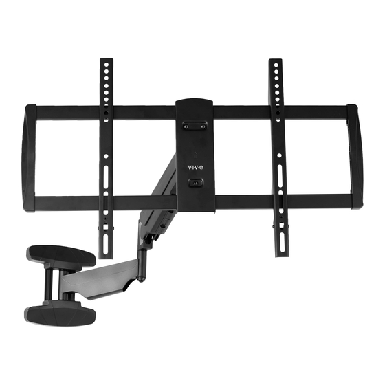
Pneumatic Spring Mantle / Wall TV Mount
Instruction Manual
SKU: MOUNT-MM01B
Scan the QR code with your mobile device or follow the link
for helpful videos and specifications related to this product.
https://vivo-us.com/products/mount-mm01b
GET IN TOUCH | Monday-Friday from 7:00am-7:00pm CST
help@vivo-us.com
www.vivo-us.com
Chat live with an agent!
309-278-5303
Advertisement
Table of Contents

Related Manuals for Vivo MOUNT-MM01B


Summary of Contents for Vivo MOUNT-MM01B
- Page 1 Pneumatic Spring Mantle / Wall TV Mount Instruction Manual SKU: MOUNT-MM01B Scan the QR code with your mobile device or follow the link for helpful videos and specifications related to this product. https://vivo-us.com/products/mount-mm01b GET IN TOUCH | Monday-Friday from 7:00am-7:00pm CST help@vivo-us.com...
- Page 2 CAUTION! DO NOT INSTALL INTO DRYWALL ALONE. VERIFY YOUR WALL CONSTRUCTION. USE WOOD STUDS TO MOUNT. We include mounting for brick and concrete walls. If unsure, please contact us at vivo-us. com, email at help@vivo-us.com, or call us at 309-278-9303.
- Page 3 ASSEMBLY STEPS STEP 1 While holding Arm (A) closed, cut the zip tie and gently release Arm (A). STEP 2 (Option A) Wood Wall Installation Use Arm (A) to mark mounting holes on wall where stud is located. Use of a stud finder and level is highly recommended.
- Page 4 STEP 2 (Option B) Concrete/Brick Wall Installation Use Arm (A) to mark mounting holes on wall. Use of a stud finder and level is highly recommended. Using a 12/25” (12mm) drill bit, drill holes at least 3.74” (95mm) deep into marked locations. Press Concrete Anchors (W-B) into holes, then insert ST8x90mm Screws (W-A) into the top hole, leaving 6mm of thread exposed.
- Page 5 STEP 4 Assemble TV Plate (B) to Arm (A) using M6 Nuts (S-A) and Wrench (T-C). STEP 5 Remove Screws (D1) from VESA Brackets (D) and set aside. Attach VESA Brackets (D) to back of the monitor using screws (M-A through M-E) and M8 Washers (M-E). If screws are too long, spacers (M-F, M-G) may be required.
- Page 6 STEP 6 Hang VESA Brackets (D) over TV Plate (B) and secure using Screws (D1). STEP 7 Adjust the tension of Arm (A) using 6mm Allen Wrench (T-B). Turn 6mm Allen Wrench (T-B) clockwise to decrease tension, and counter clockwise to increase.
- Page 7 STEP 8 Remove bottom cover from Arm (A). Organize cables and re-attach the cover. STEP 9 Adjust the tilt using 4mm Allen Wrench (T-A) and the rotation using Wrench (T-C).
- Page 8 AVG. RESPONSE TIME (within office hrs) - 23% within < 15m - 38% within < 30m - 61% within < 1hr - 83% within < 2hr - 92% within < 3hr FOR MORE VIVO PRODUCTS, CHECK OUT OUR WEBSITE AT: www.vivo-us.com...
Need help?
Do you have a question about the MOUNT-MM01B and is the answer not in the manual?
Questions and answers