Table of Contents
Advertisement
Quick Links
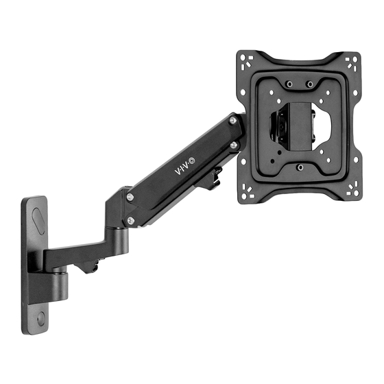
Premium Aluminum TV Wall Mount
Instruction Manual
SKU: MOUNT-G200B
Scan the QR code with your mobile device or follow the link
for helpful videos and specifications related to this product.
https://vivo-us.com/products/mount-g200b
GET IN TOUCH | Monday-Friday from 7:00am-7:00pm CST
help@vivo-us.com
www.vivo-us.com
Chat live with an agent!
309-278-5303
Advertisement
Table of Contents

Related Manuals for Vivo MOUNT-G200B


Summary of Contents for Vivo MOUNT-G200B
- Page 1 Premium Aluminum TV Wall Mount Instruction Manual SKU: MOUNT-G200B Scan the QR code with your mobile device or follow the link for helpful videos and specifications related to this product. https://vivo-us.com/products/mount-g200b GET IN TOUCH | Monday-Friday from 7:00am-7:00pm CST help@vivo-us.com www.vivo-us.com...
- Page 2 CAUTION! DO NOT INSTALL INTO DRYWALL ALONE. VERIFY YOUR WALL CONSTRUCTION. USE WOOD STUDS TO MOUNT. We include mounting for brick and concrete walls. If unsure, please contact us at vivo-us. com, email at help@vivo-us.com, or call us at 309-278-5303.
- Page 3 ASSEMBLY STEPS STEP 1 OPTION A: Wood Wall OPTION B: Concrete Wall Using the wall plate on the arm (A), mark Using the wall plate on the arm (A), mark drilling drilling locations. Use of a stud finder is highly locations.
- Page 4 STEP 3 Remove lower nut from VESA plate (B) using the wrench (E), and loosen the upper two nuts until 3mm of screw thread is exposed for each one. STEP 4 OPTION A: Flat Back Monitor Mount VESA plate (B) to TV using bolts (M-A, M-B, M-C, or M-D) with washers (M-E or M-F), making sure the two nuts are facing towards the top of the TV.
- Page 5 STEP 5 Hang TV with VESA plate onto head of arm (A). Reinstall lower nut to secure the plate, and tighten all nuts using the wrench.
- Page 6 STEP 6 Adjust gas spring tension using the 6mm Allen wrench (G). Turn counter-clockwise to increase lift, and clockwise to decrease. Adjust the tilt joint support using the 4mm Allen wrench (F). NOTE: use a large flat-blade screwdriver to tighten the socket set screw if the joint makes a popping noise. STEP 7 Use built in cable clips to manage cables.
- Page 7 Adjust as Desired...
- Page 8 - 92% within < 3hr www.vivo-us.com : < 15 M AVG. RESOLUTION TIME (within office hrs) Chat live with an agent! : 5M 4S 309-278-5303 AVG. RESOLUTION TIME (within office hrs) FOR MORE VIVO PRODUCTS, CHECK OUT OUR WEBSITE AT: www.vivo-us.com...
Need help?
Do you have a question about the MOUNT-G200B and is the answer not in the manual?
Questions and answers