
Subscribe to Our Youtube Channel
Related Manuals for Acuity Brands Lighting Pathway VIA 12 Series

Summary of Contents for Acuity Brands Lighting Pathway VIA 12 Series
- Page 1 ETHERNET SWITCHES 6750, 6750-P, 6752-P, 6754-P Models Running firmware 5.X User Guide REV 1.0 June 2020 Pathway Connectivity 1439 17 Ave SE • Calgary, AB • T2G 1J9 +1 (403) 243-8110 support@pathwayconnect.com...
- Page 2 Copyright © Pathway Connectivity A Division of Acuity Brands Lighting Canada (“Pathway”) and its licensors. All rights reserved. This software and, as applicable, associated media, printed materials and “on-line” or electronic documentation (the “Software Application”) constitutes an unpublished work and contains valuable trade secrets and proprietary information belonging to Pathway and its licensors.
-
Page 3: Table Of Contents
C O N T E N T S ABOUT VIA ETHERNET SWITCHES ..........1 INSTALLATION INSTRUCTIONS ............1 PANEL LAYOUTS ................3 FRONT PANEL ..................3 MODEL 6750, 6750-P �������������������������������������������������������������������������������������������3 MODEL 6752-P, 6754-P ����������������������������������������������������������������������������������������3 REAR PANEL ..................3 MODEL 6750 ���������������������������������������������������������������������������������������������������������3 MODEL 6750-P �����������������������������������������������������������������������������������������������������4 MODEL 6752-P �����������������������������������������������������������������������������������������������������4 MODEL 6754-P �����������������������������������������������������������������������������������������������������4 SFP+ PORTS ���������������������������������������������������������������������������������������������������������5 opticalCON PORTS ����������������������������������������������������������������������������������������������5... - Page 4 RETAINING DEVICE SETTINGS FROM UNKNOWN DOMAINS ������������������������14 USING OLDER VERSIONS OF PATHSCAPE WITH NEW DEVICES ������������������14 SOFTWARE (PATHSCAPE) CONFIGURATION ........15 NETWORK SETUP ����������������������������������������������������������������������������������������������15 DEVICE PROPERTIES ����������������������������������������������������������������������������������������16 ADVANCED CONFIGURATION ���������������������������������������������������������������������������22 PORT PROPERTIES AND CONFIGURATION ........32 BASIC PROPERTIES ������������������������������������������������������������������������������������������32 NETWORK PROPERTIES �����������������������������������������������������������������������������������34 VLAN PROPERTIES ��������������������������������������������������������������������������������������������35 NETWORK PROTOCOL SUPPORT ��������������������������������������������������������������������35 PoE PROPERTIES (NOT SHOWN ON VIA12 MODEL 6750)������������������������������37...
- Page 5 DEFINITIONS ������������������������������������������������������������������������������������������������������64 SOFTWARE CONFIGURATION OF VLANs ��������������������������������������������������������64 VLAN GUIDELINES ���������������������������������������������������������������������������������������������64 APPENDIX 3: PLANNING CHARTS ..........65 VLAN PLANNING CHART �����������������������������������������������������������������������������������65 SWITCH PLANNING CHARTS ����������������������������������������������������������������������������67 APPENDIX 4: RING PROTECTION ..........69 REQUIREMENTS AND LIMITATIONS �����������������������������������������������������������������69 DEFINITIONS ������������������������������������������������������������������������������������������������������69 APPENDIX 5: RAPID SPANNING TREE PROTOCOL .....70 APPENDIX 6: QoS SETTINGS ............71 APPENDIX 7: ELECTRICAL AND COMPLIANCE INFORMATION .72 ELECTRICAL INFORMATION ..............72...
-
Page 6: About Via Ethernet Switches
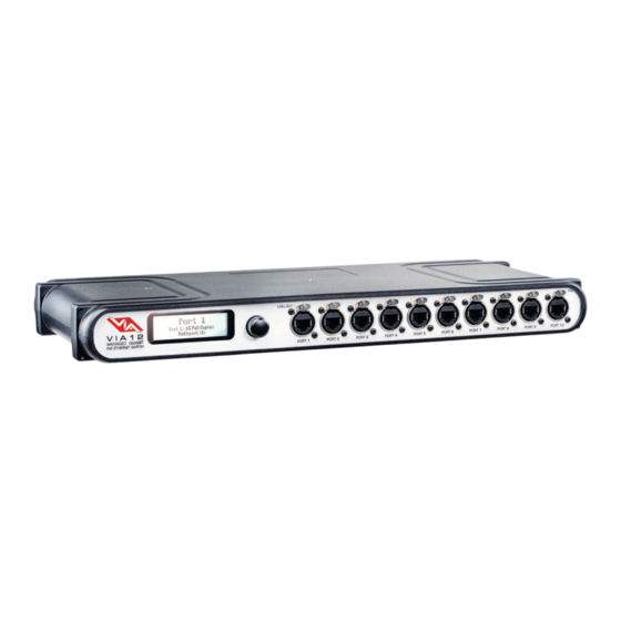
ABOUT VIA ETHERNET SWITCHES VIA™ Gigabit Ethernet Switches are designed for live entertainment Ethernet systems, including audio, video and DMX-over- Ethernet networks. This manual covers models 6750, 6750-P, 6752-P and 6754-P. VIA Ethernet Switches are intended specifically for signal routing between Pathport DMX-over-Ethernet gateways, or similar equipment, and Ethernet-aware lighting and audio control products, such as consoles and controllers and end equipment. - Page 7 All VIA Switches are intended for installation in a dry, indoor location. Ambient operating conditions are 14°F to 122°F (-10°C to 50°C); 5-95% relative humidity, non-condensing. Warning: The AC socket outlet shall be installed near the equipment and shall be easily accessible.
-
Page 8: Panel Layouts
PANEL LAYOUTS FRONT PANEL MODEL 6750, 6750-P Rotary Encoder Turn to Highlight Green LED (PoE Active) Push to Select RJ45 etherCON Amber LED (6750-P model) Connector (Link Active) Backlit LCD LINK/ACT PORT 1 PORT 2 PORT 3 PORT 4 PORT 5 PORT 6 PORT 7 PORT 8... -
Page 9: Model 6750
MODEL 6750-P Female RJ45 etherCON Connector Link/Status LEDs for IEC Power Connector for SFP+ ports Push tab to release cable 100 - 240 VAC Input ATTENTION Risk of electric shock. Disconnect power before opening. Risque de decharge electrique. Debrancher le pouvoir avant d'ouvrier. -
Page 10: Sfp+ Ports
SFP+ PORTS Models 6750 and 6750-P have two SFP+ compatible ports on the rear of the device. These require the user to provide an SFP or SFP+ fiber transceiver to allow connection to fiber networks. See Appendix 1: SFP+ Fiber Adapter Selection for more information on selecting a fiber transceiver. -
Page 11: Security
SECURITY BACKGROUND INFORMATION On January 1, 2020, California will be the first state to enforce cybersecurity and IoT related legislation. Oregon, New York and Massachusetts are following suit. California’s law is Title 1.81.26 “Security of Connected Devices” and mandates that we equip our products with security features that are appropriate to the nature and function of the device. By law, this encompasses all products that are assigned Internet Protocol addresses which can connect to the Internet directly or indirectly. -
Page 12: Introducing Security Domains
INTRODUCING SECURITY DOMAINS To simplify the process of managing security on your network, Pathscape 3 introduces the concept of a “Security Domain”. Below we will describe how to create a Security Domain and add or remove devices from it. In the Device tab of Pathscape 3 there is a new view that shows you the name of the device’s domain and a padlock icon showing its current state. -
Page 13: Creating A Security Domain
CREATING A SECURITY DOMAIN • After starting Pathscape, the online devices will populate the Device View. • Choose the Security Domain view from the Select View dropdown • Each device running V5 firmware will have a Red “Unsecured” value in the Security Domain column. •... - Page 14 • Print the Recovery Key. • You may also click on the Recovery Key, Select All and Copy the key to the Clipboard and store it in a safe place. • Press Continue to add the devices to the Domain. The devices will have an amber padlock and their properties will be read-only.
-
Page 15: Administering A Domain
• As security parameters are verified, the amber padlocks will turn green and the properties of those devices will be read/ writable. ADMINISTERING A DOMAIN To administer a domain, click on the Security menu and select Administration. This will bring up the Security Domain Admin Login window. - Page 16 Factory Default If you want to clear the security settings of a device and remove it from the domain, choose Factory Default. Only devices in the Security Domain shown in this dialog box will be available to be defaulted. For devices that you do not have a password for, you must have physical access to factory default them before you regain network configurability.
-
Page 17: Local Security - Using Via Without Pathscape
LOCAL SECURITY - USING VIA WITHOUT PATHSCAPE VIA12 switches have features that use unsecure protocols, like Art-Net Trap & Convert. You may not intend to use Pathscape, but “bad actors” could potentially access the switch and change the configuration. Therefore it is prudent to configure Local Security to protect your network if you want to use Art-Net Trap &... -
Page 18: Recovering A Domain
RECOVERING A DOMAIN If you lose the Administrator password (or it was maliciously changed without your consent), you can recover the domain, retaining its configuration and set new passwords. • From the menu, choose Security > Recover Domain. • Type in the 20-digit Recovery Key and press Continue. •... -
Page 19: Retaining Device Settings From Unknown Domains
• From the menu choose Security > Administration and Change Passwords to set a new User password. RETAINING DEVICE SETTINGS FROM UNKNOWN DOMAINS There are times when you don’t know the password of a Security Domain, but you’d like to retain all its configuration. Without logging in to a Domain, all devices that appear with amber padlocks are read-only. -
Page 20: Software (Pathscape) Configuration
SOFTWARE (PATHSCAPE) CONFIGURATION Wherever possible, we recommend using a PC with Pathscape to configure your VIA switch(es). For in-depth information on using Pathscape, see the Pathscape manual. Pathscape is available for macOS and Windows from the Software section of our website: https://www.pathwayconnect.com/index.php/products/software/176-pathscape. Use the QR Code below to visit the download page. -
Page 21: Device Properties
DEVICE PROPERTIES The following fields are shown in the Device Property Panel in Pathscape. Some are editable, while others are read-only. NOTE: If all properties are read-only (greyed out and uneditable), make sure you are logged into the correct Security Domain. SECURITY PROPERTIES Property Description... - Page 22 Property Description Serial Number Factory-assigned, Pathway serial number. Read-only. Checking this will lock the local controls on the front panel of the device. Scrolling menus allow you to read properties, but changing properties is disallowed. There is a 30-second delay upon boot before the Front Panel Lockout takes Front Panel Lockout effect.
- Page 23 NETWORK PROPERTIES Property Description IP Mode Determines how IP settings are obtained. Options are Disabled, Static and Dynamic. User-set Internet Protocol address (IPv4) for this switch. If VLANs are enabled, the IP IP Address address is applied by default to the Management VLAN ID#. User-set subnet mask.
- Page 24 VLAN PROPERTIES To enable/disable VLANs, use VLAN Global Properties under the VLAN Config Tab. The below properties will appear read-only in the Properties Pane (greyed-out); these are only configurable via the VLAN Global Properties button, as shown above. Property Description Shows whether VLANs are Enabled or Disabled, globally, on your entire network.
- Page 25 RING PROTECT PROPERTIES Property Description Ring Protect Mode Set function for Ring Protect Mode. Specifies the VLAN ID# used to determine the integrity of the ring. May not be used Ring Protect Control for any other traffic. Valid ID# is any ID outside the range set in VLAN setup. Default is VLAN VLAN 4095.
- Page 26 ADVANCED PROPERTIES Property Description User ID Custom numeric identification for external databases. VIA12 [6750, 6750-P, 6752-P, 6754-P] - Manual REV 1.0 • June 2020...
-
Page 27: Advanced Configuration
ADVANCED CONFIGURATION VLAN CONFIGURATION As described above, use the VLAN Config tab in Pathscape to configure network VLANs. A VLAN (Virtual Local Area Network) is a group of ports on the switch (or switches) that are configured to pass traffic to one another, but not to ports on any other VLAN. - Page 28 VLAN GLOBAL PROPERTIES Plan your VLAN layout before attempting configuration. The creation of a map of the network, showing which devices and which ports to associate with a given VLAN, is strongly recommended prior to configuration. EXTREMELY IMPORTANT NOTE: When configuring one or multiple VIA switches using Pathway’s software- based configuration tools, be certain the port connected to your computer is on the same VLAN ID# as the management and is not on a tagged port.
- Page 29 Once you have set up the number of VLANs you need, you may edit the names of any of the available VLANs by using the VLAN Names panel. Double-click on the VLAN Name, give it a name and then click the button to save changes.
- Page 30 If the Management VLAN is accidentally set to a value outside the VLAN range, it may be necessary to use the Factory Default option to restore communication with the management processor and allow further configuration. See Factory Default section for instructions. The VLAN range and individual VLAN configuration must be done prior to activating the Ring Protect feature.
- Page 31 IP Mode must be set to “Static” if the VIA is to act as a DHCP server. Only one DHCP server may be active on any given VLAN. Setting the IP Mode to “Dynamic” does NOT enable the DHCP server – see below. If the IP Mode is set to “Dynamic”...
- Page 32 VLAN IGMP PROPERTIES When using multicast data packets, such as streaming ACN (sACN), bandwidth efficiency may be improved by using IGMP (Internet group management protocol) to enable multicast filtering. Property Description IGMP Snooping Enable/disable IGMP snooping – allows the switch to correctly filter multi-cast traffic IGMP Querier Enable/disable the IGMP querier –...
- Page 33 RING PROTECT CONFIGURATION For Ring Protect mode to function, VLAN support must be enabled. Property Description Status of Ring Protect Mode. Disabled (default): Ring Protection feature is turned off Ring Protect Mode Master: Only one switch may be set as the Master. Transit: All other switches must be set as Transit.
- Page 34 RAPID SPANNING TREE Property Description Rapid Spanning Tree Enable / Disable Rapid Spaning Tree Protocol (RSTP) The Rapid Spanning Tree algorithm detects and prevents network loops. Networks with loops will have very poor performance. The interaction between RSTP and the Ring Protect system may cause long network re-configuration times when the ring topology is changed.
- Page 35 QUALITY OF SERVICE (QoS) Quality of Service determines the relative priority of different data packets, which in turn determines which packets should receive preferential routing from a VIA switch. QoS is often used for the distribution of video and audio signals, including the Dante®...
- Page 36 FACTORY DEFAULT In the event of a loss of communication with the device (eg. Management VLAN accidentally set to a value outside the VLAN range), it is possible to reset the switch to factory settings. To factory default a switch, turn the encoder knob to the switch main menu, which is the default menu showing the switch’s name and IP address.
-
Page 37: Port Properties And Configuration
PORT PROPERTIES AND CONFIGURATION Port status and properties may be reviewed by expanding the device in the device tree, and clicking on the subdevice/port. The properties for that port will then be shown in the Properties Panel. The following fields are shown in the subdevice/port properties panel. Some are editable, while others are read-only. BASIC PROPERTIES Property Description... - Page 38 Property Description Disable: Disables the port. Auto Negotiate (default, recommended): Allows the switch and the connected device to determine the fastest mutually supported connection speed. Read-only. 10Mbit Half Duplex 10Mbit Full Duplex Link Mode 100Mbit Half Duplex 100Mbit Full Duplex 1Gbit Full Duplex 10Gbit Full Duplex (SFP+ Ports Only) Link Status...
-
Page 39: Network Properties
LLDP PARTNER Link Layer Discovery Protocol (LLDP) is an industry-standard method for device announcement and reporting described in the IEEE 802.1AB standard. Any Ethernet-aware device may announce itself using LLDP, not just switches. This feature is particularly useful when using VLANs as you can tell which device is connected to a port, even if the port is not on the management VLAN. -
Page 40: Vlan Properties
VLAN PROPERTIES Property Description Untagged (default): Only data belonging to the port’s specified VLAN ID# will be transmitted. Typically set when connected to end equipment. VLAN Tagged Tagged/Uplink: All traffic on all VLANs will be transmitted. Typically set when connected to another switch. VLAN Assigns the selected port to the specified VLAN. - Page 41 By default, Art-Net Universe 0-0 is ignored by the VIA and the packets discarded. When Alternate Art-Net Mapping is enabled, VIA switches will map Art-Net Universe 0-0 to sACN Universe 1. When Alternate Art-Net Mapping is disabled, Art- Net Universe 0-0 will be ignored by the VIA and Art-Net Universe 0-1 will be routed as sACN Universe 1. Property Description When enabled, Art-Net data packets with broadcast address destinations are trapped...
-
Page 42: Poe Properties (Not Shown On Via12 Model 6750)
PoE PROPERTIES (NOT SHOWN ON VIA12 MODEL 6750) Property Description Enabled by default, this option allows the user to completely disable PoE on a given port. Any PoE allocation set with the following parameter will be ignored. Ports 1-12 only. The PoE class as reported by connected device. -
Page 43: Sfp/Sfp+ Transceiver (Sfp+ Ports Only)
PoE MAX ALLOCATION Allows you to set an upper limit to the power available to a connected device, such as a Pathport gateway or Vignette wall station. Use Max Allocation to ensure critical devices will have power. Also use Max Allocation to compensate for Class 0 device power allocation;... -
Page 44: Upgrading Device Firmware
UPGRADING DEVICE FIRMWARE Firmware upgrades may only be done using Pathscape. The most recently released firmware is bundled with the most recent version of Pathscape. To ensure you have the most up- to-date firmware available for upgrading, ensure you have downloaded the most recent version of Pathscape from the Pathway site, https://www.pathwayconnect.com. -
Page 45: Front Panel Ui And Menu
FRONT PANEL UI AND MENU The VIA12 models 6750, 6750-P, 6752-P and 6754-P feature a front panel UI, consisting of an LCD and a rotary pushbutton encoder for navigating menus and selecting options. If configuring the switch via a PC and Pathscape is not possible or practical, it is still easy to do using the front panel UI. This section will show the menu structure and descriptions of menu options. -
Page 46: Menus
Some menus, such as Network Settings, require the user to scroll down to accept or discard any changes made. The <Back> option will always move the menu up one level. The current menu will time out after approximately 30 seconds. FRONT PANEL LOCKOUT If using Pathscape, it is possible to enable the option Front Panel Lockout, which disables the ability to make any changes to the switch from the front panel UI. - Page 47 Menu Item Description Set subnet mask to be used by the management processor. Only valid masks are shown. Subnet Mask Turn knob to select from list of valid masks. Set default gateway for the management processor. Only valid gateways are accepted. Gateway Turn knob to set each octet.
-
Page 48: Device Info/Status
DEVICE INFO/STATUS This menu allows review of several device properties. These are non-editable. Device Info/Status Serial #: PPXXXXXXX MAC: XX:XX:XX:XX:XX:XX Firmware Version: 5.0.4 PoE Used: 7.0W PoE Allocated: 50.0W PoE Remaining: 50.0W <Back> Menu Item Description Serial # Factory-assigned, Pathway serial number. Read-only. Factory-assgiend media access control (MAC) address. -
Page 49: Advanced Settings
ADVANCED SETTINGS This menu contains advanced settings pertaining to VLANs, Ring Protect, Rapid Spanning Tree, Art-Net Alternate Mapping, and QoS (Qualit of Service). There are several sub-menus here for VLAN Setup and Configuration. Advanced Settings VLAN Support: Enabled VLAN Setup Ring Protect Setup Rapid Spanning Tree: Disabled Artnet Alt Mapping: Enabled... - Page 50 Menu Item Description Disabled (default) VLAN Support Enabled. Must be enabled to show VLAN Setup and Ring Protect feature. Specifies lowest VLAN ID# available. VLAN Range Start:<x> Valid range: 1 to 4095. Default is 1. Specifies highest VLAN ID# available. VLAN Range End: <x>...
- Page 51 Menu Item Description Specifies the VLAN ID# used to determine the integrity of the ring. It may not be used for any other traffic. Valid ID# Ring Protect Setup Control VLAN: <x> is any ID outside the range set in VLAN setup. Default is VLAN 4095.
- Page 52 VLAN SETUP These properties determine the size of the VLAN table, and which VLAN has communication with the switch management processor. For efficient switch operation, the VLAN range should be kept as small as necessary. VLAN Setup VLAN Range Start: 1 VLAN Range End: 10 Management VLAN: 1 VLAN Config/Status...
- Page 53 VLAN CONFIG/STATUS: NETWORK SETUP This menu operates the same as the switch’s main Network Setup menu. Configure these for each VLAN ID#. Network Setup IP Mode: Static IP Address: X.X.X.X Subnet Mask: X.X.X.X Gateway: X.X.X.X <Back> Menu Item Description Determines how IP settings will be obtained. Disabled (default): No IP assigned.
- Page 54 If the IP Mode is set to “Dynamic” on a system with no active DHCP server, the switch will auto-generate IP settings in accordance with zeroconf standards, in the IP range of 169.254.x.x/16. This range may not be suitable for connection to entertainment systems VLAN CONFIG/STATUS: DHCP SERVER VIA switches can automatically assign IP addresses to connected devices, using a DHCP (Dynamic Host Configuration...
- Page 55 Menu Item Description Shows if currently entered DHCP Server Pool entires are valid. This property is not editable, it is simply a check to ensure DHCP Server is setup correctly. Server Config Valid: Pool range is valid and can be applied. Invalid: Pool range is invalid.
- Page 56 The IGMP Querier establishes a table of active multicast groups by querying connected devices about which multicast groups each device wishes to join. For example, a gateway will request the multicast groups associated with the sACN universes that the gateway is patched to. Each switch operating an IGMP Querier on a VLAN must have valid IP settings on that VLAN.
- Page 57 Menu Item Description Specifies the VLAN ID# used to determine the integrity of the ring. This VLAN may not be Control VLAN: <x> used for any other traffic. Valid ID# is any ID outside the range set in VLAN setup. Default is VLAN 4095.
- Page 58 ART-NET ALTERNATE MAPPING This feature is used in conjunction with the Art-Net Trap-and-Convert option, which is set from the Port Configuration menu. This feature does not affect unicast Art-Net packets. Menu Item Description Turn Art-Net Alternate Mapping on or off. ArtNet Alt Mapping Enabled (Default) Disabled...
- Page 59 Menu Item Description Off (Default) Disables QoS-based routing. All traffic is treated equally. Traffic priority is observed using a weighted algorithm to ensure timely delivery of high priority Standard traffic and eventual delivery of lower priority packets. Traffic priority is strictly observed, using Dante-specified weighting. Lower priority traffic may Dante Strict be dropped or ignored to ensure delivery of Dante’s high priority packets <Back>...
-
Page 60: Port Status And Configuration Menu
PORT STATUS AND CONFIGURATION MENU Port Status may be reviewed by turning to encoder knob to reach the desired port, from the main screen showing the switch name and IP address. The LCD shows the following information. <Switch Name> <Port Name> IP: 10.30.142.169/8 Port <x>: <Link Speed>... - Page 61 Once VLANs are enabled and the VLAN range is set from the Base Configuration menu, by default a port is set as Untagged (Normal) with a VLAN ID# of 1, or the lowest ID# of the VLAN range. Ports set as Untagged only transmit data packets in the VLAN specified by the ID# and are typically connected to end equipment.
- Page 62 Although performance depends on DMX frame rate, conversion of no more than 48 Art-Net universes by one VIA at one time is recommended. To take advantage of IGMP, this feature assumes the DMX gateways can receive sACN instead of Art-Net. Enabled by default, this menu item allows the user to completely disable PoE on a given port.
- Page 63 Menu Item Description Reports the maximum draw allowed by the PoE class, or the limit set by the user, whichever PoE Allocated: <x> is the lower amount. Sets the PoE allocation for the port. Default is 15.4W. Max PoE Allocation: <x>...
- Page 64 Menu Item Description Device Model Product Model name. For example, “Pathport OCTO” Serial Number Device Serial Number Firmware Version Current device operating firmware version MAC Address Device Media Access Control (MAC) Address PORTS 1-12: LINK MODE Allows review and editing of the port’s communication speed. Link Mode Disabled *Auto Negotiate*...
-
Page 65: Port 13 & 14: Configuration/Status: Sfp+ Ports
Range is from 10Mb – Half Duplex (a common value for older devices) to 1Gb – Full Duplex. The port may also be disabled. NOTE: It is not possible to force a device to connect at a speed faster than the device’s network interface hardware will support. - Page 66 Menu Item Description Disabled. Turns port off. Link Mode 1GBit Full Duplex 10G Full Duplex VLANs must be enabled in the Advanced Settings menu for this option to be shown. Untagged (Normal): Only data belonging to the port’s specified VLAN ID# will be VLAN transmitted.
- Page 67 REV 1.0 • June 2020 VIA12 [6750, 6750-P, 6752-P, 6754-P] - Manual...
-
Page 68: Appendix 1: Sfp/Sfp+ Fiber Adapter Selection
APPENDIX 1: SFP/SFP+ FIBER ADAPTER SELECTION The VIA Gigabit switches allow the end user to provide a fiber adaptor. The adaptors are typically referred to as an SFP (Small Form Pluggable transceiver) or mini-GBIC (gigabit interface converter). Pathway part number 6799 is an SFP 850nm Ethernet Optical Transceiver that is compatible with VIA12, VIA16 and VIA8, capable of 1Gbps. -
Page 69: Appendix 2: Virtual Local Area Network (Vlan)
APPENDIX 2: VIRTUAL LOCAL AREA NETWORK (VLAN) A VLAN (Virtual Local Area Network) is a group of ports on the switch (or switches) that are configured to pass traffic to one another, but not to ports on any other VLAN. When multiple VLANs are established, some ports on the switch may need to be configured specifically to pass all VLAN traffic, to ensure overall traffic is routed correctly. -
Page 70: Appendix 3: Planning Charts
APPENDIX 3: PLANNING CHARTS VLAN PLANNING CHART VLAN ID # Label IP Address Subnet Mask Default Gateway IGMP Snooping IGMP Querier DHCP Server Art-Net Alternate Mapping QoS Level VLAN ID # Label IP Address Subnet Mask Default Gateway IGMP Snooping IGMP Querier DHCP Server Art-Net Alternate... - Page 71 VLAN ID # Label IP Address Subnet Mask Default Gateway IGMP Snooping IGMP Querier DHCP Server Art-Net Alternate Mapping QoS Level VLAN ID # Label IP Address Subnet Mask Default Gateway IGMP Snooping IGMP Querier DHCP Server Art-Net Alternate Mapping QoS Level REV 1.0 •...
-
Page 72: Switch Planning Charts
SWITCH PLANNING CHARTS SWITCH LABEL: Base IP: Subnet: Gateway: QoS (Off/Standard/Dante): VLAN (Enable/Disable): Range: Management ID#: Art-Net Alternate Mapping (On/Off - On is default): VIA12 [6750, 6750-P, 6752-P, 6754-P] - Manual REV 1.0 • June 2020... - Page 73 REV 1.0 • June 2020 VIA12 [6750, 6750-P, 6752-P, 6754-P] - Manual...
-
Page 74: Appendix 4: Ring Protection
APPENDIX 4: RING PROTECTION Ethernet wiring schemes are based on a ‘star’-wiring topology. Ring (or loop) data wiring – where the last device in a chain is wired back to the first device – is forbidden. Only one data path between any two devices is allowed. But star-wiring layouts are prone to single point failures. -
Page 75: Appendix 5: Rapid Spanning Tree Protocol
APPENDIX 5: RAPID SPANNING TREE PROTOCOL The Rapid Spanning Tree Protocol (RSTP) is another technology to prevent network loops. EAPS (described above in Ring Protection) requires more setup, as it needs a dedicated master and multiple transit switches, but this allows it to function within a few DMX frames during fail-over. -
Page 76: Appendix 6: Qos Settings
APPENDIX 6: QoS SETTINGS Quality of Service priorities are determined by the Differentiated Services Code Point (DSCP) field contained in each data packet header. DSCP values may range from 1 to 64, and are mapped to four egress (output) queues. The egress queues are, in turn, numbered from 1 (Best Effort) to 4 (Highest Priority). -
Page 77: Appendix 7: Electrical And Compliance Information
APPENDIX 7: ELECTRICAL AND COMPLIANCE INFORMATION ELECTRICAL INFORMATION MODEL 6750 • Power input: 100-240VAC, 50/60Hz • 0.3A Maximum current draw MODEL 6750-P • Power input: 100-240VAC, 50/60Hz • 1.3A Maximum current draw • Integrated PoE supply: 100W; Class 3 PoE (15.4W maximum per port) MODEL 6752-P, 6754-P •...
Need help?
Do you have a question about the Pathway VIA 12 Series and is the answer not in the manual?
Questions and answers