Table of Contents
Advertisement
Quick Links
Advertisement
Table of Contents

Related Manuals for Acuity Brands Lighting Pathway PWVIA DIN P16 RJ45 SFPSLOT POE

Summary of Contents for Acuity Brands Lighting Pathway PWVIA DIN P16 RJ45 SFPSLOT POE
- Page 1 DIN-mount Ethernet Switches PWVIA DIN Models Running firmware 6.X or later User Guide March 2022 © 2022 Acuity Brands, Inc. • One Lithonia Way, Conyers GA 30012 Pathway Connectivity | #103 - 1439 17th Ave SE Calgary, AB Canada T2G 1J9 Phone: + 1 866 617 3074...
- Page 2 Copyright © Pathway Connectivity A Division of Acuity Brands Lighting Canada (“Pathway”) and its licensors. All rights reserved. This software and, as applicable, associated media, printed materials and “on-line” or electronic documentation (the “Software Application”) constitutes an unpublished work and contains valuable trade secrets and proprietary information belonging to Pathway and its licensors.
-
Page 3: Table Of Contents
C O N T E N T S ABOUT VIA DIN-MOUNT ETHERNET SWITCHES - PWVIA DIN ..1 INSTALLATION INSTRUCTIONS ............1 PANEL LAYOUTS ................2 FRONT PANEL ..................2 MODEL PWVIA DIN P16 RJ45 SFPSLOT POE ����������������������������������������������������2 MODEL PWVIA DIN P8 RJ45 SFPSLOT POE ������������������������������������������������������3 REAR PANEL ..................3 MODEL PWVIA DIN P16 RJ45 SFPSLOT POE, PWVIA DIN P8 RJ45 SFPSLOT POE �����������������������������������������������������������������������������������������������������������������������3... - Page 4 shipped prior to January 1, 2020 �������������������������������������������������������������������������7 CREATING A SECURITY DOMAIN ............8 ADMINISTERING A DOMAIN ..............12 MANAGE SECURITY DOMAIN ���������������������������������������������������������������������������12 MANAGE DEVICES ���������������������������������������������������������������������������������������������16 RECOVERING A DOMAIN ..............18 RETAINING DEVICE SETTINGS FROM UNKNOWN DOMAINS ..20 USING OLDER VERSIONS OF PATHSCAPE WITH NEW DEVICES ..20 INTRODUCING PATHWAY ssACN (Secure sACN) ......21 DOMAIN AUTO ssACN PASSWORD ������������������������������������������������������������������21 CUSTOM ssACN PASSWORD ���������������������������������������������������������������������������21...
- Page 5 RING PROTECT PROPERTIES (EAPS) ��������������������������������������������������������������30 PoE PROPERTIES ����������������������������������������������������������������������������������������������32 ADVANCED PROPERTIES ����������������������������������������������������������������������������������32 VLAN CONFIG ..................34 VLAN GLOBAL PROPERTIES ����������������������������������������������������������������������������35 WARNING �������������������������������������������������������������������������������������������������36 VLAN PROPERTIES/SERVICES �������������������������������������������������������������������������37 RESOLVING VLAN CONFLICTS ............40 PORT PROPERTIES AND CONFIGURATION ........42 BASIC PROPERTIES ������������������������������������������������������������������������������������������43 LINK DETAILS �����������������������������������������������������������������������������������������������������43 NETWORK PARTNER (LLDP) �����������������������������������������������������������������������������44 VLAN PROPERTIES ��������������������������������������������������������������������������������������������45 Art-Net TRAP AND CONVERT ����������������������������������������������������������������������������45 POE PROPERTIES ����������������������������������������������������������������������������������������������46...
- Page 6 APPENDIX 4: EAPS & RSTP - “RING PROTECTION” ....58 Requirements and Limitations ���������������������������������������������������������������������������58 Definitions for EAPS �������������������������������������������������������������������������������������������58 Software Configuration of Ring ��������������������������������������������������������������������������59 APPENDIX 5: QoS SETTINGS ............60 APPENDIX 6: ELECTRICAL, COMPLIANCE & OTHER INFORMATION ......................61 ELECTRICAL INFORMATION ..............61 PWVIA DIN P16 RJ45 SFPSLOT POE ����������������������������������������������������������������61 PWVIA DIN P8 RJ45 SFPSLOT POE ������������������������������������������������������������������61 COMPLIANCE ..................61 PHYSICAL .....................61...
-
Page 8: About Via Din-Mount Ethernet Switches - Pwvia Din
ABOUT VIA DIN-MOUNT ETHERNET SWITCHES - PWVIA DIN PWVIA Ethernet Switches are designed for live entertainment Ethernet systems, including audio, video and DMX-over-Ethernet networks. This manual covers models PWVIA DIN P16 and PWVIA DIN P8 models. VIA Ethernet Switches are intended specifically for signal routing between Pathport DMX-over-Ethernet gateways, or similar equipment, and Ethernet-aware lighting and audio control products, such as consoles and controllers and end equipment. -
Page 9: Panel Layouts
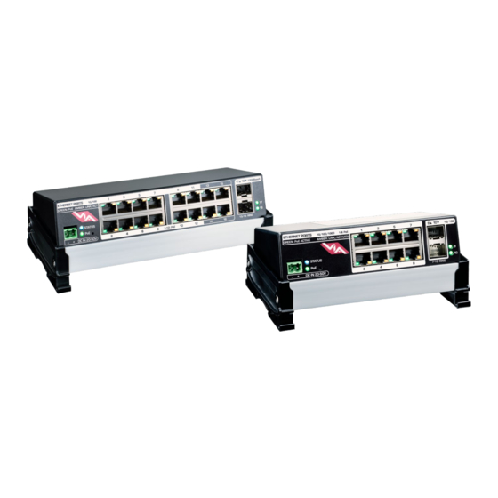
PANEL LAYOUTS FRONT PANEL MODEL PWVIA DIN P16 RJ45 SFPSLOT POE Female 10/100 RJ45 connectors (x16) Amber LED (Link Active) Green LED (PoE Active) 2x SFP Ports for Fiber transceivers or copper direct-attach cables Link/Status LEDs indicators for fiber ports Factory Reset button (recessed) Processor Status and PoE LED indicators DC power input 20-50VDC... -
Page 10: Model Pwvia Din P8 Rj45 Sfpslot Poe
MODEL PWVIA DIN P8 RJ45 SFPSLOT POE Amber LED (Link Active) Green LED (PoE Active) Mini-GBIC ports Status LEDs Female RJ45 Status LEDs for SFP/SFP+ for SFP+ Gigabit Ethernet Fiber modules ports Ports, PoE-enabled DC Power Input, (x2) (x8) 20-50V REAR PANEL MODEL PWVIA DIN P16 RJ45 SFPSLOT POE, PWVIA DIN P8 RJ45 SFPSLOT POE Earth ground... -
Page 11: Rj45 Ethernet Ports
RJ45 ETHERNET PORTS The PWVIA DIN P16 has 16 female RJ45 Ethernet ports on the front panel. These are 10/100 Mbit. The first 12 of these support Class 3 Power-over-Ethernet (PoE); the last 4 do not. The PWVIA DIN P8 has 8 female RJ45 Ethernet ports on the front panel. These are 1Gbit. All 8 ports support Class 3 Power-over-Ethernet (PoE). -
Page 12: Configuration
CONFIGURATION All configuration of the PWVIA DIN P16 and PWVIA DIN P8 must be done with the free software tool, Pathscape. To download Pathscape, visit the Pathway website at https://www.pathwayconnect.com For instructions on how to set properties and send transactions to devices, refer to the Pathscape manual. Rev. -
Page 13: Security
SECURITY BACKGROUND INFORMATION On January 1, 2020, California will be the first state to enforce cybersecurity and IoT related legislation. Oregon, New York and Massachusetts are following suit. California’s law is Title 1.81.26 “Security of Connected Devices” and mandates that we equip our products with security features that are appropriate to the nature and function of the device. -
Page 14: Security Domains
SECURITY DOMAINS To simplify the process of managing security on your network, Pathscape (beginning with version 3.0) introduced the concept of a “Security Domain”. Below we will describe how to create a Security Domain and add or remove devices from it. In the Device tab of Pathscape there is a view that shows you the name of the device’s domain and a padlock icon showing its current state. -
Page 15: Creating A Security Domain
CREATING A SECURITY DOMAIN • After starting Pathscape, the online devices will populate the Device View. • Choose the Security Domain view from the Select View dropdown • Each device running V5 or later firmware will have a Red “Unsecured” value in the Security Domain column. •... - Page 16 • Add all the Unsecured devices on your network by checking the top checkbox labeled “Unsecured” and and then click Next. If you wish to add some but not all devices to this domain, click on the checkbox next to each device you’d like to add, and then click Continue.
- Page 17 • Clicking the Print button will open a Print Dialog, from which you may choose a printer to print to. • You may also right-click on the Recovery Key, then Select All and Copy the key to the clipboard and store it in a safe place.
- Page 18 • To configure the devices, you must log in to the domain as a user by pressing the Log In button in the toolbar. Note: The Security Toolbar option under the Window menu must be checked You can also click on the Security menu and select the Log In menu item.
-
Page 19: Administering A Domain
ADMINISTERING A DOMAIN To administer a domain, click on the Administration button on the Security Toolbar, or click the Security menu and select Administration. Enter the Admin password for the Security Domain, and the Domain Administrator Utilities window will appear. The Domain Admin Utilities window is broken down into to main sections, Manage Security Domain and Manage Devices. - Page 20 DOMAIN MANAGEMENT CHANGE PASSWORDS If your staffing changes, it is a good idea to change the passwords on the domain. Click this button to change the current Security Domain Admin and User passwords. All devices should be online when you change the password. Once you have entered both Admin and User passwords, click the Change Passwords button to confirm the changes.
- Page 21 CHANGE DOMAIN NAME Click this button to change the name of the current Security Domain. Enter a new name for the current domain, and click Change Domain Name. The window will close, and you will be logged out of the current domain, and the Domain Name will be changed to the new value.
- Page 22 Click on the checkboxes next to the devices you want to add to the Domain, and click the Add Devices button. To add all the listed devices, click the top checkbox next to “Unsecured” which will auto-check all the devices’ checkboxes. REMOVE Click this button to remove devices from the current Security Domain.
-
Page 23: Manage Devices
MANAGE DEVICES This section is broken down further into functions that relate to Factory Defaulting devices as well as setting or restoring Device Restore Points. FACTORY DEFAULT FACTORY DEFAULT If you want to clear the settings of a device and return it to the factory defaults, click Factory Default. Note that only devices in the Security Domain shown in this dialog box will be available to be defaulted. - Page 24 DEVICE RESTORE POINTS With the release of firmware V6.0, VIA Switches including models PWVIA RM P12, PWVIA DIN P16, and PWVIA DIN P8 will support Device Restore Points. Creating a Device Restore Point saves the device’s current configuration and settings to its internal memory, for later recall. This differs from a Pathscape show file, in that the show file is saved on a PC running Pathscape.
-
Page 25: Recovering A Domain
RECOVERING A DOMAIN If you lose the Administrator password (or it was maliciously changed without your consent), you can recover the domain, retaining its configuration and set new passwords. • From the menu, choose Security > Recover Domain. • The Reset Device Security window will open. •... - Page 26 • Type in a new Administrator Password, and click Finish. • Now you can log into the Domain Administration Utilities Panel using the new Admin password you just specified. At this point you can set a new user password as well, using the Change Passwords button, as explained above.
-
Page 27: Retaining Device Settings From Unknown Domains
RETAINING DEVICE SETTINGS FROM UNKNOWN DOMAINS There are times when you don’t know the password of a Security Domain, but you’d like to retain all its configuration. Without logging in to a Domain, all devices that appear with amber padlocks are read-only. If you save a show file, the configuration of all devices is saved. -
Page 28: Introducing Pathway Ssacn (Secure Sacn)
INTRODUCING PATHWAY ssACN (Secure sACN) Pathway ssACN (Secure streaming ACN) is a new protocol developed by Pathway using much of ANSI E1.31, but adds a layer of authentication. This feature requires device firmware version 6.0 or later. Receiving devices, like Pathport DMX/RDM gateways, share a secret password with known controllers in the venue, to verify the data source before driving the lighting rig. -
Page 29: Using Pathway Ssacn With Via
USING PATHWAY ssACN WITH VIA In general, VIA switches do not perform any protocol conversion on data traffic, except with the feature Art-Net Trap and Convert. When Art-Net Trap and Convert is enabled on a Port, Art-Net data packets with broadcast address destinations are trapped and converted to E1.31 sACN or Pathway ssACN multicast packets, as the packets enter the Port of the switch. -
Page 30: Notes About Pathway Ssacn
NOTE that the individual Port property determines what type of conversion is performed (None/Disabled, E1.31 sACN or Pathway ssACN), and the base device property determines the Pathway ssACN Password type. You may choose to convert to E1.31 sACN on some ports, Pathway ssACN on others, and disable the function on others, or any combination. See later in this manual for more detail on Art-Net Trap &... -
Page 31: Software (Pathscape) Configuration
SOFTWARE (PATHSCAPE) CONFIGURATION Configuration must be done using Pathscape. For in-depth information on using Pathscape, see the Pathscape manual. Pathscape is available for macOS and Windows from the Software section of our website: https://www.pathwayconnect.com. NETWORK SETUP PLEASE NOTE: Before any configuration and network setup can be done, including setting the IP, the VIA switch(es) must be added to a Security Domain. -
Page 32: Device Properties
DEVICE PROPERTIES The following fields are shown in the Device Property Panel in Pathscape. Some are editable, while others are read-only. NOTE: If all properties are read-only (greyed out and uneditable), make sure you are logged into the correct Security Domain. PATHWAY SECURITY DOMAIN DOMAIN NAME The name of the Security Domain the device is currently assigned to. -
Page 33: Basic Properties
BASIC PROPERTIES IDENTIFY DEVICE Checking this box causes device to commence identify behavior (flashing LCD backlight or Identify LED). DEVICE NAME A user-configured, soft label for the Gateway. If left blank (and by default) the device name displayed will be the device’s IP Address. -
Page 34: Device Time Settings
DEVICE TIME SETTINGS NTP SERVER Set the server for NTP (Network Time Protocol). This is to ensure that security certificates are valid, when connecting to SixEye RMM. We recommend using pool.ntp.org, time.windows.com, time.apple.com or other publicly available servers. If using the NTP server, ensure that the DNS Server and IP Gateway are set so the device knows how to get to the Internet to find a time server. -
Page 35: Advanced Features
DNS Server Set Domain Name Server for the device here. The DNS should be specified if using and NTP server and/or SixEye RMM. ADVANCED FEATURES QUALITY OF SERVICE (QoS) Quality of Service determines the relative priority of different data packets, which in turn determines which packets should receive preferential routing from a VIA switch. -
Page 36: Vlan Properties
VLAN PROPERTIES To enable/disable VLANs, click the Global VLAN Properties Button. For more information on setting VLAN Properties, see the VLAN Configuration section later in this manual. Art-Net TRAP AND CONVERT When enabled, Art-Net data packets with broadcast address destinations are trapped and converted to E1.31 sACN or Pathway ssACN multicast packets, as the packets enter the port of the switch. -
Page 37: Ring Protect Properties (Eaps)
SixEye STATUS This shows the status of the SixEye connection. Unprovisioned (default). No Internet Connection. There is a problem with the device finding an Internet connection. Check the device’s IP Settings, specifically the Gateway. DNS Failure. The device has found a connection, but there is a problem with resolving URLs. Check the device’s DNS settings. - Page 38 RING STATE Shows the current state of the Ring. Values are: Ring Idle. The ring is not currently doing anything; seen after enabling Ring Protect but before any attempt to initialize the ring has happened. Ring Complete. The ring is initialized and working. The Master switch is monitoring the health of the ring. Ring Failed.
-
Page 39: Poe Properties
PoE PROPERTIES PoE EXTERNAL SUPPLY DETECTED Will show true if the VIA Switch detects an external PoE supply, false if it does not (if applicable). Read-only. PoE EXTERNAL SUPPLY POWER (W) When attaching an external PoE supply, the power rating in Watts must be entered here for the Switches’ PoE to function properly. - Page 40 DEVICE RESTORE POINT VALID Shows True of False depending on whether the current Device Restore Point is valid. Rev. 11/03/22 PWVIA DIN Ethernet Switches - Manual...
-
Page 41: Vlan Config
VLAN CONFIG Use the VLAN Config tab to configure network VLANs. A VLAN (Virtual Local Area Network) is a group of ports on the switch (or switches) that are configured to pass traffic to one another, but not to ports on any other VLAN. When VLANs are established, ports that connect switches to switches must be “tagged”... -
Page 42: Vlan Global Properties
VLAN GLOBAL PROPERTIES In order to use VLANs, VLAN Support must be enabled in VLAN Global Properties, which is accessed by clicking the button in the top-right corner of the window. You can also click this button in the VLAN Properties section of the base device properties. -
Page 43: Warning
You will then see several transactions populate in the transaction editor, which will be automatically sent. To discard changes, click the button. The Advanced Properties panel will allow for global configuration of VLAN Ranges, Management VLAN, and VLAN Support on and off. WARNING Changing any of these global VLAN properties may cause you to immediately lose connectivity to same or all of your devices. -
Page 44: Vlan Properties/Services
VLAN PROPERTIES/SERVICES VLANs must be enabled prior to configuring these services. You will find the VLAN Enable/Disable Property in the VLAN Global Properties Window in the VLAN Config window or under the Settings Menu. NETWORK PROPERTIES IP MODE Disabled: No IP assigned to this VLAN by this VIA Static: IP settings manually set by user (default for VLAN ID#1 / management VLAN). - Page 45 DHCP PROPERTIES DHCP SERVER Dynamic Host Configuration Protocol (DHCP). Disabled (default). Enabled: Only one switch on a given VLAN may have an active DHCP service, and that VLAN must have a static IP itself. One switch with multiple VLANs may have multiple DHCP servers. DHCP SERVER RANGE START Sets start IP address in the DHCP pool.
- Page 46 NOTES ON IGMP The IGMP Querier establishes a table of active multicast groups by querying connected devices about which multicast groups each device wishes to join. For example, a gateway will request the multicast groups associated with the sACN universes that the gateway is patched to. Each switch operating an IGMP Querier on a VLAN must have valid IP settings on that VLAN.
-
Page 47: Resolving Vlan Conflicts
RESOLVING VLAN CONFLICTS If you have set up your VLANs as described above, and you later add another VIA switch to your network that has different VLAN settings, you will likely see the following message in red at the bottom of the Pathscape window: Go to the VLAN Config tab and you will see something like this: Because the VLAN properties are stored on each physical VIA switch, when a new switch comes online with different property values, Pathscape doesn’t know which one(s) to use. - Page 48 For each VLAN ID with conflicting properties, you will need to double-click on each instance of “<Varies> (X)” and then pick the correct VLAN ID from the drop-down menu. Pathscape will then use the settings associated with those VLAN IDs chosen to clear the found conflicts Rev.
-
Page 49: Port Properties And Configuration
PORT PROPERTIES AND CONFIGURATION VIA Switch subdevices are Ethernet Ports, either copper RJ45 Ports or SFP/fiber ports . The color of the Port icon reflects its Link Status and Speed. Icon Status Copper RJ4: Link Down (no downstream device connected) Grey RJ45 Copper RJ45: 1 Gigabit (PWVIA DIN P8 Only) Blue RJ45... -
Page 50: Basic Properties
BASIC PROPERTIES SUBDEVICE NAME A user-configured, soft label for the subdevice/Port. Shown in the Device view and on the front panel display of the Switch (if equipped). SUBDEVICE NOTES A user-configured text description field, shown in the Device window. LINK DETAILS FORWARDING STATE Status of RSTP and EAPS. -
Page 51: Network Partner (Lldp)
100Mbit Full Duplex 1Gbit Full Duplex (1Gbit Copper Ports Only - PWVIA DIN P8, SFP Ports - PWVIA DIN P16, SFP+ Ports - PWVIA DIN P8) 10Gbit Full Duplex (SFP+ Ports Only - PWVIA DIN P8) LINK STATUS Reports current link status and speed. Read Only. LAST LINK CHANGE Displays the time elapsed since the last change in the Port Link Status. -
Page 52: Vlan Properties
VLAN PROPERTIES Set VLAN Properties for the selected port. VLAN TAGGED When VLANs are enabled, set port as a Tagged/Uplink to transmit all VLANs’ data between switches. Typically tagged ports are only used to connect a switch to a switch. Although it is possible to make a PC’s NIC tagged, Pathway gateways and controllers do not used tagged NICs. -
Page 53: Poe Properties
NOTES ON Art-Net TRAP AND CONVERT When enabled, Art-Net data packets with broadcast address destinations are trapped and converted to E1.31 sACN multicast packets, as the packets enter the port of the switch. The resulting sACN packets may then be filtered using the IGMP settings. - Page 54 PoE ACTIVE DRAW (W) Reports current PoE device draw in Watts. Read-only. PoE POWER ALLOCATION (W) Reports power allocation to port based on end device’s reported PoE device classification. Read-only. PoE MAX ALLOCATION Sets power allocated to port. Allows switch to determine remaining PoE power pool available, but does not prevent end devices from requesting and utilizing power in excess of this value.
-
Page 55: Upgrading Device Firmware
UPGRADING DEVICE FIRMWARE Firmware upgrades may only be done using Pathscape. The most recently released firmware is bundled with the most recent version of Pathscape. To ensure you have the most up- to-date firmware available for upgrading, ensure you have downloaded the most recent version of Pathscape from the Pathway site, https://www.pathwayconnect.com. -
Page 56: Factory Default
FACTORY DEFAULT In the event of a loss of communication with the device (eg. Management VLAN accidentally set to a value outside the VLAN range), it is possible to reset the switch to factory settings. While powered, insert the tip of a pen or paperclip into the small hole in the front panel next to the PoE LED and press and hold the reset button for 5 seconds. - Page 57 PWVIA DIN Ethernet Switches - Manual Rev. 11/03/22...
-
Page 58: Appendix 1: Sfp/Sfp+ Fiber Adapter Selection
APPENDIX 1: SFP/SFP+ FIBER ADAPTER SELECTION VIA switches allow the end user to provide a fiber adaptor. The adaptors are typically referred to as an SFP (Small Form Pluggable transceiver) or mini-GBIC (gigabit interface converter). Pathway part number PWACC SFP is an SFP 850nm Ethernet Optical Transceiver that is compatible with PWVIA RM P12, PWVIA DIN P16 and PWVIA DIN P8, capable of 1Gbps. -
Page 59: Appendix 2: Virtual Local Area Network (Vlan)
APPENDIX 2: VIRTUAL LOCAL AREA NETWORK (VLAN) A VLAN (Virtual Local Area Network) is a group of ports on the switch (or switches) that are configured to pass traffic to one another, but not to ports on any other VLAN. When multiple VLANs are established, some ports on the switch may need to be configured specifically to pass all VLAN traffic, to ensure overall traffic is routed correctly. -
Page 60: Appendix 3: Planning Charts
APPENDIX 3: PLANNING CHARTS VLAN PLANNING CHART VLAN ID # Label IP Address Subnet Mask Default Gateway IGMP Snooping IGMP Querier DHCP Server Art-Net Alternate Mapping QoS Level VLAN ID # Label IP Address Subnet Mask Default Gateway IGMP Snooping IGMP Querier DHCP Server Art-Net Alternate... - Page 61 VLAN ID # Label IP Address Subnet Mask Default Gateway IGMP Snooping IGMP Querier DHCP Server Art-Net Alternate Mapping QoS Level VLAN ID # Label IP Address Subnet Mask Default Gateway IGMP Snooping IGMP Querier DHCP Server Art-Net Alternate Mapping QoS Level PWVIA DIN Ethernet Switches - Manual Rev.
-
Page 62: Switch Planning Charts
SWITCH PLANNING CHARTS SWITCH LABEL: Base IP: Subnet: Gateway: QoS (Off/Standard/Dante): VLAN (Enable/Disable): Range: Management ID#: Art-Net Alternate Mapping (On/Off - On is default): SWITCH LABEL: Base IP: Subnet: Gateway: QoS (Off/Standard/Dante): VLAN (Enable/Disable): Range: Management ID#: Art-Net Alternate Mapping (On/Off - On is default): Rev. - Page 63 PWVIA DIN Ethernet Switches - Manual Rev. 11/03/22...
- Page 64 Rev. 11/03/22 PWVIA DIN Ethernet Switches - Manual...
- Page 65 APPENDIX 4: EAPS & RSTP - “RING PROTECTION” Ethernet wiring schemes are based on a ‘star’-wiring topology. Ring (or loop) data wiring – where the last device in a chain is wired back to the first device without RSTP or EAPS setup will quickly ‘break’ your network. Only one data path between any two devices is allowed.
- Page 66 SOFTWARE CONFIGURATION OF RING • Start with the redundant wiring segment unplugged. • Connect the computer running Pathscape to one of the end switches, in the wiring chain. • Configure the switch that is physically furthest away on the chain. Work backwards until reaching the closest switch. •...
- Page 67 APPENDIX 5: QoS SETTINGS Quality of Service priorities are determined by the Differentiated Services Code Point (DSCP) field contained in each data packet header. DSCP values may range from 1 to 64, and are mapped to four egress (output) queues. The egress queues are, in turn, numbered from 1 (Best Effort) to 4 (Highest Priority).
- Page 68 APPENDIX 6: ELECTRICAL, COMPLIANCE & OTHER INFORMATION ELECTRICAL INFORMATION PWVIA DIN P16 RJ45 SFPSLOT POE • 20-50 VDC power input, 10W maximum (Switch only) • 48-50 VDC power input, 190W maximum (including 180W distributed to up to 12 PoE devices) •...
Need help?
Do you have a question about the Pathway PWVIA DIN P16 RJ45 SFPSLOT POE and is the answer not in the manual?
Questions and answers