Advertisement
Quick Links
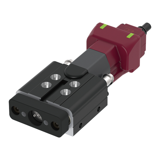
Simple-to-use ELECYLINDER with Built-in Controller
Simple-to-use ELECYLINDER with Built-in Controller
Simple-to-use ELECYLINDER with Built-in Controller
Simple-to-use ELECYLINDER with Built-in Controller
Battery-less Absolute Encoder
A A b b b s s o o lu u t t t e e e E E n n c c c o o o d d e e r r
No Battery,
a a t t t t e e r r y y y ,
No Maintenance, No Homing,
M M a a i i i i n n t t e e n n a a n n c c e e , N N o H H o o m m i i i i n n g g ,
No Going Back to Incremental.
o G G o o i i n n g B B a a c c k k t t o I I n n c c r r e e m m e e n n t t a a l l . . .
Ultra-Mini Double-guide Rod Type
Ultra-Mini Double-guide Rod Type
Ultra-Mini Slider & Ultra-Mini Table Type
Ultra-Mini Slider & Ultra-Mini Table Type
EC
EC
EC
EC
Simple & Wireless
Simple & Wireless
Simple & Wireless
Operation
Operation
Operation
2 Position Actuator
2 Position Actuator
w w w . e l e c y l i n d e r . d e
GB
GB
GD3
GD3
SL3/T3
SL3/T3
Advertisement

Related Manuals for IAI ELECYLINDER EC GD3


Summary of Contents for IAI ELECYLINDER EC GD3
- Page 1 Simple-to-use ELECYLINDER with Built-in Controller Simple-to-use ELECYLINDER with Built-in Controller Ultra-Mini Double-guide Rod Type Ultra-Mini Double-guide Rod Type SL3/T3 SL3/T3 Simple-to-use ELECYLINDER with Built-in Controller Simple-to-use ELECYLINDER with Built-in Controller Ultra-Mini Slider & Ultra-Mini Table Type Ultra-Mini Slider & Ultra-Mini Table Type Battery-less Absolute Encoder A A b b b s s o o lu u t t t e e e E E n n c c c o o o d d e e r r No Battery,...
- Page 2 Believe it: A built-in controller at this size! Ultra-Mini EleCylinder EC-T3 The following uses are available Application Example: Indexing table connector assembly equipment Transport/assembly Setting/cutting out Cutting out Insertion Select from three types according to the application Type Slider Table EC-SL3 EC-T3 EC-GDS3/GDB3...
-
Page 3: Maintenance
Ultra-Mini EleCylinder resolves all kinds of small air cylinder problems! Problem Speed adjustment is di cult with small cylinders ... Problem solved! EleCylinder speed can be set easily at any value needed, from low speed to high-speed operation Speed can be set with numbers from 1% (low speed) to 100% (high speed), enabling the same... - Page 4 Introducing the functions made possible by EleCylinder Status shown by body LEDs LEDs on the body clarify the operation status. With forward end/backward end display added, the status is clear at a glance. LED left LED right Color Operation status LED left LED right Orange...
- Page 5 EleCylinder Actuator Power I/O cable Series Type Lead Stroke Options cable length connector length Slider type NPN speci cation Lead 2mm Blank (base width 32mm) (interface box connection), no options Lead 4mm Rod type with rolling RCON-EC connection speci cation (Note 2) (Note 3) GDS3 bushing...
-
Page 6: Mounting Orientation
Mounting Orientation : Can be mounted : Cannot be mounted Mounting orientation Series Type Vertical mounting (Note 1) Horizontal mounting to side Horizontal mounting suspended (Note 2) (Note 2) GDS3 GDB3 ... -
Page 7: Mounting Methods
Mounting Methods Mount according to the mounting method for the applicable type. Slider type (SL3) Using base bottom surface Using base interior counterbored hole screw hole *The stainless steel sheet must be removed during the process. Hex socket bolt Set screw Hex socket bolt *Be careful, as the screw depth... - Page 8 EleCylinder EC-SL3 Body Width Lead Pulse Coupled Screw Motor Motor Model Speci cation Items Series Type Lead Stroke Actuator cable length Power I/O cable connector length Options 50mm See power I/O cable connector length See actuator cable length table below See options below table below 200mm...
- Page 9 EleCylinder Main Speci cations Item Description Item Description Lead Ball screw lead (mm) Drive system Rolling screw ø4mm, rolled C10 Payload Max. payload (kg) Positioning ±0.05mm repeatability Max. speed (mm/s) Speed / Lost motion - (notation not available due to 2-point positioning function) Min.
- Page 10 EleCylinder Dimensions CAD drawings can be downloaded from our website. www.elecylinder.de (Note) When the slider is returning to its home position, please be careful of interference from surrounding objects, as it will travel until it reaches the M.E. ST: Stroke (Note) Fix the cable so that its base does not move.
- Page 11 EleCylinder EC-GDS3 Body Width Lead Pulse Coupled Screw Motor Motor Model Speci cation Items GDS3 Series Type Lead Stroke Actuator cable length Power I/O cable connector length Options 10mm See power I/O cable connector length See actuator cable length table below See options below table below 30mm...
- Page 12 EleCylinder Main Speci cations Item Description Item Description Lead Ball screw lead (mm) Drive system Rolling screw ø4mm, rolled C10 Payload Max. payload (kg) Positioning repeatability ±0.05mm Lost motion Max. speed (mm/s) - (notation not available due to 2-point positioning function) Speed / Min.
- Page 13 EleCylinder Dimensions CAD drawings can be downloaded from our website. www.elecylinder.de (Note) When returning to the home position, the rod will move to the M.E. Be careful of interference with surrounding objects. ST: Stroke (Note) Fix the cable so that its base does not move. M.E: Mechanical end The cable can be separated and replaced.
- Page 14 EleCylinder EC-GDB3 Body Width Lead Pulse Coupled Screw Motor Motor Model Speci cation Items GDB3 Series Type Lead Stroke Actuator cable length Power I/O cable connector length Options 10mm See power I/O cable connector length See actuator cable length table below See options below table below 50mm...
- Page 15 EleCylinder Main Speci cations Item Description Item Description Lead Ball screw lead (mm) Drive system Rolling screw ø4mm, rolled C10 Payload Max. payload (kg) Positioning repeatability ±0.1mm (Stroke 10), ±0.05mm (Stroke ≥ 20) Lost motion Max. speed (mm/s) - (notation not available due to 2-point positioning function) Speed / Min.
- Page 16 EleCylinder Dimensions CAD drawings can be downloaded from our website. www.elecylinder.de (Note) When returning to the home position, the rod will move to the M.E. Be careful of interference with surrounding objects. ST: Stroke (Note) Fix the cable so that its base does not move. M.E: Mechanical end The cable can be separated and replaced.
- Page 17 EleCylinder EC-T3 Body Width Lead Pulse Coupled Screw Motor Motor Model Speci cation Items Series Type Lead Stroke Actuator cable length Power I/O cable connector length Options 10mm See power I/O cable connector length See actuator cable length table below See options below table below 50mm...
- Page 18 EleCylinder Main Speci cations Item Description Item Description Lead Ball screw lead (mm) Drive system Rolling screw ø4mm, rolled C10 Payload Max. payload (kg) Positioning ±0.05mm repeatability Max. speed (mm/s) Speed / Lost motion - (notation not available due to 2-point positioning function) Min.
- Page 19 EleCylinder Dimensions CAD drawings can be downloaded from our website. www.elecylinder.de (Note) Upon home return, the table will move to the M.E. Be careful of interference with surrounding objects. ST: Stroke (Note) Fix the cable so that its base does not move. M.E: Mechanical end The cable can be separated and replaced.
- Page 20 Refer to P. 118 of the EleCylinder Catalog V10 for precautions on axis operations using a wireless connection. (Note) Customers cannot change WL to WL2, or WL2 to WL. Please contact IAI for this. When using wireless communication with RCON-EC...
- Page 21 Individual Options Air cylinder mounting plates These plates provide compatibility for mounting with some models of air cylinders. Plates can be mounted on the base side to enable mounting in accordance with the air cylinder body mounting hole positions. Mounting to the table surface is not supported.
- Page 22 EC maintenance part model list SL3/GDS3/GDB3/T3 (1) Motor unit (2) Actuator cable mounting box (3) Actuator cable assembly (4) Interface box conversion cable (5) Interface box (6) Stainless steel sheet The numbers in the table correspond to the numbers in the schematics. (1) Motor unit (5)-1 Interface box (Accessories: Bolts, screws, hex wrench)
- Page 23 Push-motion operation Push-motion operation is a function that keeps the rod or table pushed up against the workpiece, as with an air cylinder. Please check the usage instructions and precautions below prior to use. [Precautions] · When pushing, the static and dynamic allowable moments of the guide must be taken into consideration. [Push force adjustment] (Example) ·...
- Page 24 Selection notes When connecting the Ultra-Mini EleCylinder to a PLC, three connection methods are available. Select from these three connection methods. Take note of the connection restrictions and items to be prepared separately. *Contact our sales department to change the connection method after purchase. 1.
-
Page 25: List Of Accessories
System Con guration Accessories: Included when designated in actuator model number Options Options: Separate order required teaching software Options (See P. 28) EC connection unit RS232 connection version (Refer to RCON Catalog V2) <Wires> <Model: RCM-101-MW> Select AWG18 or higher <... - Page 26 Basic Controller Speci cations Speci cation item Speci cation content Number of controlled axes 1 axis Power supply voltage 24VDC ±10% Power capacity (Note 1) Rated 0.7A, max. 1.1A Brake release power supply 24VDC ±10%, 200mA (only for external brake release) Generated heat Inrush current (Note 2) Momentary power failure resistance...
- Page 27 Interface Box Speci cation (I/O speci cation) Input Output Input voltage 24VDC ±10% Load voltage 24VDC ±10% Input current 5mA per circuit Maximum load current 50mA/1 point Speci cations ON/OFF ON voltage: MIN. 18VDC Residual voltage 2V or less voltage OFF voltage: MAX.
- Page 28 Consumption current 150mA (supplied from controller) TB-03- Model Please contact IAI for the current supported versions. Ambient operating temperature 0 ~ 40°C (no condensation or freezing) Con guration Wireless or wired connection Ambient operating humidity...
- Page 29 *1 The pulse width of owing inrush current is less than 5ms. *2 This power supply can vary the output voltage according to the load in order to enable parallel operation. The power supply unit is therefore for use with IAI controllers only. 16.4 *3 Parallel connection cannot be used under the following conditions.
- Page 30 Maintenance Parts (Cable) When individually ordered cables or replacements must be ordered, refer to the model number below. Table of Compatible Cables Cable type Cable model Power / I/O cable (user-wired speci cation) CB-EC-PWBIO-RB Power / I/O cable (user-wired speci cation, four-way connector) CB-EC2-PWBIO-RB Power / I/O cable (RCON-EC connection speci cation) CB-REC-PWBIO-RB...
- Page 31 Maintenance Parts (Cable) Four-Way Connector Cable The cable exit direction from the connector can be freely selected from four directions. The cable management for the connector is the same as that of power I/O cable CB-EC-PWBIO -RB/CB-REC- PWBIO-RB.
- Page 32 Hongqiao Rd., Shanghai 200030, China Bangna, Bangna, Bangkok 10260, Thailand Phone: +86-21-6448-4753, Fax: +86-21-6448-3992 Phone: +66-2-361-4457, Fax: +66-2-361-4456 IAI, the IAI-logo, EleCylinder™ and the EleCylinder™-logo are trademarks or product names of IAI Corporation or of the subsidiaries in USA, China,Thailand or Germany...
Need help?
Do you have a question about the ELECYLINDER EC GD3 and is the answer not in the manual?
Questions and answers