Table of Contents
Advertisement
Quick Links
1. Parts Confirmation
Please contact your sales representative if any of these parts are missing or incorrect:
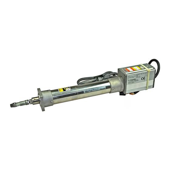
- ERC Actuator: Slider type (ERC-SA6/SA7) or Rod type (ERC-RA54/RA64)
- Relay Cable: CB-ERC-PWBIO***
- CD with Manuals (PDF format)
Optional: - Teaching Pendant
RCA-T/E
2. Installation
a. Install the Actuator.
Screw diameter
Standard torque
for bolting
b. Mount to the Actuator.
- Slider Type: Use the 4 tapped holes (M5, depth 10mm) located on the top of the slider.
The maximum torque for mounting is 7.5Nm (0.77Kgf.m).
- Rod Type: Be sure to use a wrench to prevent adding rotational moment
to the rod (see picture to the right). Use a 13mm wrench for the RA54
model and a 17mm wrench for the RA64 model.
3. Wiring
Connect the connector end of the relay cable to the actuator cable connector.
Individually connect the open ends of the cable to: (1) 24V DC control/motor power supply, (2) Emergency stop circuit,
(3) I/O circuit, (4) Ground wire, (5) Brake release switch (when brake option is used).
Because the HOLD signal is a normally closed contact, it is ON during operation and OFF during pause. If there is no
PLC software at the time of adjustment, change parameter #15 (refer to the last page of this Quick Start Guide). You
can temporarily short it to 0V. (It becomes necessary to use the teaching pendant or PC for operation). Afterwards,
you must remove this short if you plan to automatically operate it with a PLC.
4. LED Indicator for Power Supply
Before supplying 24V power, confirm that the brake release switch is OFF and that the
emergency stop circuit is not operating. Supply power. The LED located on top of the
motor cover should be GREEN.
A RED light indicates a cutoff in the motor power supply, or that an alarm is occurring. At this
point, you should refer to the "Troubleshooting" section of your Operating Manual to resolve
this problem.
ERC Quick Start Guide
- PC Software Kit
- Insulated PIO Terminal Block
RCB-101-MW
Slider type
Flange
SA6/SA7
RA54
M5
M4
4.3Nm
2.3Nm
(0.44Kgf.m)
(0.23Kgf.m)
Slider type
www.intelligentactuator.com
RCB-TU-PIO-A/B
Rod type
Foot Bracket
RA64
RA54
M6
M6
6.7Nm
6.7Nm
(0.68Kgf.m)
(0.68Kgf.m)
Rod type
Foot bracket
- SIO Converter
RCB-TU-SIO-A/B
RA64
M8
14.0Nm
(1.43Kgf.m)
Rod type
Flange
LED
Advertisement
Table of Contents

Related Manuals for IAI ERC Series


Summary of Contents for IAI ERC Series
- Page 1 ERC Quick Start Guide 1. Parts Confirmation Please contact your sales representative if any of these parts are missing or incorrect: - ERC Actuator: Slider type (ERC-SA6/SA7) or Rod type (ERC-RA54/RA64) - Relay Cable: CB-ERC-PWBIO*** - CD with Manuals (PDF format) Optional: - Teaching Pendant - PC Software Kit - Insulated PIO Terminal Block...
- Page 2 5. Input Data & Operate with PC or Teaching Pendant Connect the teaching pendant or PC to the mini DIN connector located at the rear of the motor cover. Input desired data such as position, speed, acceleration/deleceration, position range. Other operations can be performed such as position movement verfication, direct teaching of positions, and data correction based on the load situation.
- Page 3 Operation with the PC Software or Teaching Pendant As an example, we will set 50mm as Position No. 1 and move the actuator to this position. 1. Using the PC Software Click "Edit Position Data" button Run the software Action Action "Edit Position Data"...
- Page 4 2. Using the Teaching Pendant (Standard RCA-T model) Move the cursor to Position No. 1 Action Select "Edit/Teach" & hit enter Action & press the Select Mode Axis1 Edit/Teach Axis1 EEdit/Teach (Position) No Position Vel mm/s EMonitor EError List EUser Parameter EUser Adjustment Add/Del: No -->Return Select Mode-->...
- Page 5 2. Supply power to the actuator and turn ON. 3. Start the IAI RoboCylinder Software and connect to the actuator (auto). 4. Back up the parameters to a local file on the PC by choosing PARAMETERS g Edit g Select Axis. Click the DISK button to save a copy locally.
Need help?
Do you have a question about the ERC Series and is the answer not in the manual?
Questions and answers