Table of Contents
Advertisement
Quick Links
ELECYLINDER
Instruction Manual
EC-ST15
First Edition
ME3799-1C
Specifications
ch.
Installation
ch.
Wiring
ch.
Operation
ch.
Preventive/
ch.
Predictive Maintenance
Parameters
ch.
Troubleshooting
ch.
Maintenance and
ch.
Inspection
External Dimensions
ch.
Life
ch.
Warranty
ch.
Appendix
ch.
1
2
3
4
5
6
7
8
9
10
11
12
Advertisement
Table of Contents
Troubleshooting

Related Manuals for IAI ELECYLINDER


Summary of Contents for IAI ELECYLINDER
- Page 1 ELECYLINDER EC-ST15 Instruction Manual First Edition ME3799-1C Specifications Installation Wiring Operation Preventive/ Predictive Maintenance Parameters Troubleshooting Maintenance and Inspection External Dimensions Life Warranty Appendix...
- Page 3 • This instruction manual is an original document dedicated for this product. • This product cannot be used in ways not shown in this instruction manual. IAI shall not be liable for any result whatsoever arising from the use of the product in any other way than what is noted in the manual.
- Page 4 ELECYLINDER Instruction Manual Configuration Control Product name Instruction manual name number ELECYLINDER Quick Start Guide ME3765 Instruction Manual ELECYLINDER ME3799 (this document) RCM-101-MW/RCM-101-USB PC Compatible Software for RC/EC ME0155 Instruction Manual Touch Panel Teaching Pendant TB-02/02D Instruction Manual ME0355 TB-03 Instruction Manual...
-
Page 5: Table Of Contents
Contents Safety Guide ······························································································· Intro-1 Precautions for Handling ··············································································· Intro-9 International Standard Compliance ································································ Intro-11 Precautions for Handling Wireless Operation ··················································· Intro-12 Precaution for Axis Operation with Wireless Connection ···································· Intro-14 Part Names ······························································································ Intro-15 Chapter 1 Specifications Checking the product ······························································ 1-1 Components ································································································... - Page 6 Basic operation ······································································ 4-1 Teaching tool connections and testing operation ··························· 4-2 Teaching pendant connection ·········································································· 4-2 ELECYLINDER test operation ········································································· 4-3 Stop position/operating conditions (AVD) setting/adjustment ············ 4-4 Stop position setting/adjustment (forward end/backward end) ································ 4-5 Operating conditions (AVD) setting/adjustment ··················································· 4-6 Pressing operation setting ··············································································...
- Page 7 Chapter 5 Preventive/Predictive Maintenance Preventive/predictive maintenance ············································· 5-1 Maintenance information ·························································· 5-2 Total travel count ·························································································· 5-2 Total travel distance ······················································································ 5-2 Overload warning level ·················································································· 5-3 Setting maintenance information ················································ 5-4 Switching to maintenance information window ···················································· 5-4 Basic operation ···························································································· 5-5 Chapter 6 Parameters Precautions regarding parameters ·············································...
- Page 8 Chapter 8 Maintenance and Inspection Precautions for maintenance and inspection work ························· 8-1 Inspection items and schedule ·················································· 8-3 Stopper cylinder ··························································································· 8-3 Grease supply timing (Guideline) ····································································· 8-3 Visual inspection items ···························································· 8-4 External visual inspection ··············································································· 8-4 Internal visual inspection ················································································ 8-5 Cleaning ·············································································...
-
Page 9: Safety Guide
Safety Guide Safety Guide The Safety Guide is intended to permit safe use of the product and thus to prevent risks and property damage. Be sure to read it before handling the product. Intro-1... - Page 10 Safety Guide Safety Precautions for Our Products Common safety precautions for the use of robots in various operations are indicated here. Operation Precautions Model ● This product is not intended or designed for applications where high levels of Selection safety are required, and so cannot guarantee that human lives will be protected.
- Page 11 Safety Guide Operation Precautions Transportation ● When transporting heavy objects, do the work with two or more persons or utilize equipment such as a crane. ● When working with two or more persons, make it clear who is to be in charge and communicate well with each other to ensure safety.
- Page 12 (4) Locations where the product may come in contact with water, oil or chemical spray (2) Cable wiring ● Use IAI genuine cables for connecting the actuator and controller, and for the teaching tools. ● Do not scratch cables, bend them forcibly, pull them, coil them, snag them, or place heavy objects on them.
- Page 13 Safety Guide Operation Precautions Installation (4) Safety measures ● When working with two or more persons, make it clear who is to be in charge Startup and communicate well with each other to ensure safety. ● When the product is operating or in the ready mode, take safety measures (such as the installation of safety/protection fences) so that nobody can enter the area within the robot's movable range.
- Page 14 Safety Guide Operation Precautions Trial Operation ● When working with two or more persons, make it clear who is to be in charge and communicate well with each other to ensure safety. ● After teaching or programming, carry out trial operation step by step before switching to automatic operation.
- Page 15 Safety Guide Operation Precautions Maintenance ● When releasing the brake on a vertically oriented actuator, be careful that it does not fall under its own weight, catching the operator's hand or damaging Inspection workpieces. ● The slider or rod may be misaligned from the stop position if the servo is turned OFF.
- Page 16 Safety Guide Precaution Indications The safety precautions are divided into "Danger", "Warning", "Caution" and "Notice" according to the warning level, as follows, and described in the Instruction Manual for each model. Level Degree of risk to persons and property Symbol This indicates an imminently hazardous situation which, if the product Danger Danger...
-
Page 17: Precautions For Handling
3. Make sure to secure the ELECYLINDER properly in accordance with this instruction manual. If the ELECYLINDER is not securely fixed, this may lead to abnormal noise, vibration, breakdown or shortened product life. 4. Make sure to observe the usage conditions and environment of the product. - Page 18 In extreme cases, flaking may occur on the guide. 7. Base oil may separate from the grease and leak from the inside of the ELECYLINDER to the exterior due to the operating environment, mounting orientation, operating conditions, etc. Protect the peripheral equipment if base oil adhesion negatively affects them.
-
Page 19: International Standard Compliance
To be checked in EC Declaration of Conformity. EC Declaration of Conformity proving conformity to RE Directive may be modified without notice according to addition of conformed models, specification change and so on. Visit our homepage (http:/www.iai-robot/) or contact our sales site if necessary. -
Page 20: Precautions For Handling Wireless Operation
Precautions for Handling Wireless Operation When the option for wireless communication support (model: WL, WL2) is selected, a wireless communication circuit board is built into the ELECYLINDER. Certificates and self-declarations regarding the wireless function are handled under the model name below for the wireless circuit board. - Page 21 [EU Member States] • For details of the applicable standards, please refer to above mentioned international standards compliances. • Import Corporation Name : IAI Industrieroboter GmbH * The product can be used in any country which is a member of EU. Intro-13...
- Page 22 - ประเทศผ ู ้ผล ิ ต : ญี ่ ป ุ่ น (Made in Japan) - ผู ้นํ า เข ้า : IAI Robot (Thailand) Co., Ltd. • Número de Certificación 【México / Mexico】 • Nombre de la Empresa Solicitante :IAI Corporation...
-
Page 23: Precaution For Axis Operation With Wireless Connection
Precautions for Axis Operation with Wireless Connection Touch Panel Teaching Pendant TB-03 (V2.30 or later) can operate the option model code -WL2 ELECYLINDER with wireless connection. For operation with wireless connection, secure safety by following the precautions below before use. -
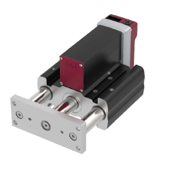
Page 24: Part Names
Part Names Part Names The figure below shows EC-ST15. In this manual, the right and left sides of the actuator are expressed in the way it is placed horizontally as shown in the figure below, and is looked at from the motor side. Stopper cylinder Right side Status indicator LED... - Page 25 Part Names Motor (built in controller) Teaching port Status indicator LED Power I/O connector [Teaching port] This connector is for the connection of a teaching pendant or PC software. When connecting, remove the cap. [Status indicator LED] The LED on the right side as seen from the motor side shows the servo ON/OFF status and alarm status, and the LED on the left side as seen from the motor side displays the wireless status.
- Page 26 Intro-18...
- Page 27 ELECYLINDER Chapter Specifications Checking the product ··············································· 1-1 Components ··········································································· 1-1 How to read the model nameplate ··············································· 1-2 How to read the model number ··················································· 1-3 Mechanical specifications ·········································· 1-4 Stopper cylinder EC-ST15 ························································· 1-4 Duty ratio ············································································· 1-10 Options ·······························································...
-
Page 29: Checking The Product
The following table shows the product configuration for the standard specification. See the packing list for the details of the enclosed components. In the unlikely case that any model number errors or missing parts come to light, contact your local IAI distributor. Body... -
Page 30: How To Read The Model Nameplate
1.1 Checking the product How to read the model nameplate Model number → Serial number → [Nameplate position]... -
Page 31: How To Read The Model Number
1.1 Checking the product How to read the model number ( ) ST15L Series Type Lead Stroke Power / I/O cable length Options Incremental encoder specification, 50 mm 3 mm Blank NPN specification, no option RCON-EC connection specification Brake Cable length Non-motor end specification ·... -
Page 32: Mechanical Specifications
1.2 Mechanical specifications 1.2 Mechanical specifications Stopper cylinder EC-ST15 [Lead and Payload (Energy-Saving: Disabled)] Maximum payload Maximum Lead Model number pressing force (mm) Horizontal Vertical (kg) (kg) EC-ST15L -50 -①(-②) 12.5 Legend ①Cable length ②Option Stroke and Max. Speed (Energy-Saving: Disabled)] Lead (mm) - Page 33 1.2 Mechanical specifications [Payload by Speed/Acceleration (Energy-Saving: Disabled)] At low load capacity, the acceleration/deceleration can be increased. The maximum acceleration/deceleration is 0.5G in the horizontal direction and 0.5G in the vertical direction. For % input, 0.5G is set as 100%. Lead 3 Orientation Horizontal...
- Page 34 1.2 Mechanical specifications [Lead and Payload (Energy-Saving: Enabled)] Maximum payload Maximum Lead Model number pressing force (mm) Horizontal Vertical (kg) (kg) EC-ST15L -50 -①(-②) Legend ①Cable length ②Option Stroke and Max. Speed (Energy-Saving: Enabled)] Lead (mm) (mm) (Unit: mm/s) Caution The maximum speed may not be achieved when the stroke or movement distance is short or when acceleration/deceleration is set low.
- Page 35 1.2 Mechanical specifications [Payload by Speed/Acceleration (Energy-Saving: Enabled)] At low load capacity, the acceleration/deceleration can be increased. The maximum acceleration/deceleration is 0.5G in the horizontal direction and 0.3G in the vertical direction. For % input, 0.5G is set as 100%. Lead 3 Orientation Horizontal...
- Page 36 1.2 Mechanical specifications [Actuator Specifications] Item Content Drive system Ball screw φ10mm, rolled C10 Positioning repeatability ±0.15mm Backlash 0.03mm or less Range of Stopper Use Max. payload 50kg / max. Transfer speed 40m/min Allowable Vertical Load 500N Ambient operating temperature/humidity 0 to 40°C, 85% RH or less (Non-condensing) [Pressing Force and Current Limit Value] Correlation of pressing force and current limit value...
- Page 37 1.2 Mechanical specifications [Range of Use] Use the production within 50mm of dimension Workpiece Workpiece Range of Use Workpiece Impact Speed [m/min]...
-
Page 38: Duty Ratio
1.2 Mechanical specifications Duty ratio The duty ratio is the operating rate, shown in %, of the actuator operating time within one cycle. Continuous operation is possible when the duty ratio is 100%. 1-10... -
Page 39: Options
1.3 Options 1.3 Options RCON-EC connection specification (Model: ACR) It is the code to be indicated when connected to RCON-EC. * When this option is selected, it is not available to select PN Option (PNP specification) or TMD2 Option (2-circuit power supply specification). With brake (Model: B) This is used to prevent the rod from moving during power outages or when the servo is OFF. -
Page 40: Wireless Axis Operation Specification (Model: Wl2)
Wireless axis operation specification (Model: WL2) The wireless axis operation specification includes a built-in wireless circuit board enabling wireless communication between the ELECYLINDER and the Touch Panel Teaching Pendant. Specifying WL2 enables operation testing of axis operation (movement to forward and backward ends, jog operation, inching operation) as well as the operation via wireless communication enabled with WL. -
Page 41: Accessories
1.4 Accessories 1.4 Accessories Power I/O cable Supplied when length (value other than 0) is specified in the model number cable length. Refer to Power I/O cable equipped with 4-way connector in 3.5 Wiring connections (for cables) for Cable CB-EC2-PWBIO□□□-RB equipped with the 4-way connector. (Note1) LS0/PE0 LS1/PS1... -
Page 42: Power I/O Connector
1.4 Accessories Power I/O connector Supplied when cable length is specified as "0" in the model number. Name Model number Quantity 1-1871940-6 Power I/O connector 1 pc (Tyco Electronics) 1-14... -
Page 43: Installation
ELECYLINDER Chapter Installation Precautions for transportation ···································· 2-1 Installation and storage/preservation environment ·········· 2-4 Installation environment ···························································· 2-4 Storage/preservation environment··············································· 2-5 Installation of stopper cylinder ···································· 2-6 Installation surface ··································································· 2-6 Mounting orientation Type: EC-ST15L ·········································· 2-6 Fixing bolt ·············································································· 2-7 Square nuts ············································································... -
Page 45: Precautions For Transportation
2.1 Precautions for transportation 2.1 Precautions for transportation [Handling the package] ● Do not damage or drop the package. The package is not specially designed to withstand dropping or shock due to collision. ● Do not have a single operator to carry a heavy package. Use an appropriate method for transportation. - Page 46 ● Do not carry the unit by its controller cover, front bracket, guide shaft or motor cover. ● Do not damage or drop the package during transportation. ● Do not apply excessive force to any part of the ELECYLINDER. ● The teaching port and power I/O connector are connected to the built-in controller, so be especially careful not to apply external force.
- Page 47 [Handling when assembled into machinery (system)] ● Secure rods to prevent sudden movement during transport. ● If the ELECYLINDER body or any moving part is overhanging, fix it appropriately to avoid large wobbles due to external vibration. When transporting without fixing the tip, do not apply impact of 0.3G or more.
-
Page 48: Installation And Storage/Preservation Environment
2.2 Installation and storage/preservation environment 2.2 Installation and storage/preservation environment Usage is possible in environments of pollution degree 2 or equivalent. Pollution degree 2: Environment in which generally only nonconductive pollution occurs, but temporary conductive pollution may occur due to condensation (IEC 60664-1) Installation environment Avoid the following locations for installation. -
Page 49: Storage/Preservation Environment
2.2 Installation and storage/preservation environment Storage/preservation environment ● For the storage and preservation environment, see the installation environment. However, give especial consideration to the prevention of condensation during long-term storage/preservation. ● Unless especially specified, desiccant is not included in the package at shipping. If the product is to be stored/preserved in an environment where condensation is anticipated, take condensation preventive measures. -
Page 50: Installation Of Stopper Cylinder
0.05mm/m. ● The mounting frame should have a structure rigid enough to prevent the generation of vibration. ● Also consider the necessary space for maintenance work such as ELECYLINDER replacement and inspection. Mounting orientation Type: EC-ST15L... -
Page 51: Fixing Bolt
2.3 Installation of stopper cylinder Caution Excessive greasing may cause the grease to drip from the rod. If the actuator installed vertically with the moving part oriented upward is kept stopped for long time, the grease may eventually separate, causing the base oil to flow into the motor part and leading to controller or motor/encoder breakdown. -
Page 52: Body Mounting
2.3 Installation of stopper cylinder Body mounting [When using the T-shaped slot on the body frame bottom] The unit has a T-shaped slot at the bottom of the body frame for mounting. Insert a square nut into the T-shaped slot and fix it from the back. →... - Page 53 2.3 Installation of stopper cylinder T-shaped slot dimensions Reamed hole Oblong Detailed view of Q Reamed hole hole Type EC-ST15L 92mm 8.5mm 13.5mm 13.5mm Reamed Type hole depth 8 EC-ST15L 48mm +0.03 66mm φ5H9 depth 8 Square nuts The square nuts regulated in JIS B1163 can be used for the T-shaped slots. Required bolt Minimum Square nut...
- Page 54 2.3 Installation of stopper cylinder [When using the through holes on the body frame] The unit has a through holes at the body frame for mounting. Utilize the through holes for installation. → For details regarding the position and dimensions, refer to "Chapter 9 External Dimensions".
- Page 55 2.3 Installation of stopper cylinder [When using the tapped mounting holes on the body frame bottom] The unit has a tapped mounting holes at the bottom of the body frame for mounting. Utilize the tapped mounting holes for installation. → For details regarding the position and dimensions, refer to "Chapter 9 External Dimensions".
- Page 56 2.3 Installation of stopper cylinder Tightening torque Type Fixing bolt For iron installation For aluminum surface installation surface EC-ST15L 59.3N•m 23.3N•m 2-12...
- Page 57 2.3 Installation of stopper cylinder [When using the tapped mounting holes on the back of the body frame] The unit has tapped mounting holes at the back of the body frame for mounting. Utilize the tapped mounting holes for installation. →...
-
Page 58: Installation To Front Bracket
2.3 Installation of stopper cylinder Installation to front bracket ● Use the tapped mounting holes on the front bracket so you can attach things such as fixtures. ● There are reamed holes and oblong holes on the front bracket fixing surface. Use these reamed holes if repeated attaching and detaching is required. - Page 59 2.3 Installation of stopper cylinder Caution Be careful with regard to the length of the mounting bolt and positioning pin. The use of screw-in depth greater than that of the tapped or reamed mounting holes may damage the tapped hole or reduce the mounting strength of the transported object, leading to decreased accuracy or unexpected accidents.
- Page 60 2-16...
-
Page 61: Wiring
ELECYLINDER Chapter Wiring System configuration ················································ 3-1 Electrical specifications ············································· 3-2 Specifications table ·································································· 3-2 I/O specifications ····································································· 3-3 Brake release method (for specifications with brakes) ····················· 3-4 Frame grounding ····································································· 3-4 Connection arrangement diagram ······························· 3-5 Wiring connections (for connectors) ····························· 3-7 24VDC power supply wiring ·······················································... -
Page 63: System Configuration
3.1 System configuration The following shows the system configuration. <Model: PSA-24> Supply 24VDC to the ELECYLINDER and input a signal from a master device to the ELECYLINDER. This enables the ELECYLINDER to operate. This manual introduces an example using a PLC connected as the master device. -
Page 64: Electrical Specifications
3.2 Electrical specifications 3.2 Electrical specifications Specifications table Item Content Number of controlled axes 1 axis Power supply voltage 24VDC ±10% Energy-Saving: Disabled Rated 3.5A, max. 4.2A Power capacity Energy-Saving: Enabled Max. 2.2A Brake release power supply 24VDC ±10%, 200mA (only for external brake release) Generated heat Inrush current (Note 1) -
Page 65: I/O Specifications
Non-isolated from external circuitry Non-isolated from external circuitry type logic Caution In the PIO circuit, both input and output are non-isolated. Make sure to have a grounding for external devices connected to ELECYLINDER such as PLC in common with the grounding for ELECYLINDER. -
Page 66: Brake Release Method (For Specifications With Brakes)
Frame grounding The ELECYLINDER has a built-in controller circuit board. The controller frame grounding line is connected to the ELECYLINDER body and through to ground via the ELECYLINDER mounting surface. If not grounding through the mounting surface, there are M3 tapped holes on the left and right sides of the reversing bracket of which either one can be used for the grounding wire connection. -
Page 67: Connection Arrangement Diagram
3.3 Connection arrangement diagram 3.3 Connection arrangement diagram Here the wiring connection method with a power I/O connector is introduced. [For NPN specification] 24VDC ELECYLINDER (NPN specification) Power I/O connector 24V power supply Ground Note 1 Brake release BKRLS Backward complete... - Page 68 3.3 Connection arrangement diagram Here the wiring connection method with a power I/O connector is introduced. 2-Circuit Power Supply Specification TMD2 (Option) [For NPN specification] 24VDC ELECYLINDER (NPN specification) Power I/O connector 24V power supply Ground (Driving Source) Note 1...
-
Page 69: Wiring Connections (For Connectors)
3.4 Wiring connections (for connectors) 3.4 Wiring connections (for connectors) Here the wiring connection method with a power I/O connector is introduced. 24VDC power supply wiring Connect the power wiring to the power I/O connector. Connect the wiring to the connector terminal block while referring to the connection diagram. - Page 70 3.4 Wiring connections (for connectors) 2-Circuit power supply specification TMD2 (Option) Connect the power wiring to the power I/O connector. Connect the wiring to the connector terminal block while referring to the connection diagram. Connect the [B1] connector terminal and the +24V (Driving Source) terminal of the 24VDC power supply.
-
Page 71: Plc Wiring
3.4 Wiring connections (for connectors) PLC wiring For I/O between the PLC and signals, the signal wiring must be connected to the connector terminal block. Connect the wiring to the connector terminal block while referring to the connection diagram. Connect the [B3] connector terminal and the [Backward] output terminal. Connect the [B4] connector terminal and the [Forward] output terminal. -
Page 72: Connector Wiring Method
3.4 Wiring connections (for connectors) Connector wiring method The name of each terminal is affixed to the power I/O connector. The connector nameplate name and pin number relationship is as below. Wiring inlet Wiring inlet Tool insertion slot Reference Precision screwdriver Power I/O connector internal structure looks like this. - Page 73 If an electric wire thinner than the applicable diameter or wiring longer than 10m is used, insufficient current may trigger an alarm and the performance of the ELECYLINDER may be degraded. 3-11...
-
Page 74: Brake Release Wiring
3.4 Wiring connections (for connectors) 3.5 Wiring connections (for cables) Brake release wiring For the specification with brake, when installing a forcible brake release switch, connect wiring to the [B2] connector terminal. Power capacity of 24VDC ±10%/200mA or higher is required. Connector Signal Compatible... -
Page 75: Power I/O Cable Equipped With 4-Way Connector
3.5 Wiring connections (for cables) ● The wiring on the opposite side of the connector has not been processed. ● The cable length is available from 1m to 10m. Specify the length in increments of 1m. ● The following shows a sample model number. Cable length 1m →... - Page 76 3.5 Wiring connections (for cables) Follow the process bellow to build up the connector in the orientation of your demand. 1) Slide the curved side of the cable-end to your desire direction. Straight side Curved side 2) Be sure to check that the cable is settled firmly and insert two tabs of the cover along the slits of socket.
-
Page 77: Power I/O Cable Connection
3.5 Wiring connections (for cables) Power I/O cable connection Connect the power I/O cable. Insert the connector until it clicks into place. Cable connection diagram Insert the connector until you hear the "click". Caution The connector must be inserted in a given direction. A section of the connector protrudes. -
Page 78: 24Vdc Power Supply Wiring
Connect the 24V wire (insulation color: red) to the +24V terminal of the 24VDC power supply. Connect the 0V wire (insulation color: black) to the 0V terminal of the 24VDC power supply. 24VDC power supply connection diagram 24VDC power supply ELECYLINDER/Power I/O cable Wiring Signal Function Required specifications color... - Page 79 Connect the 24V (Control) wire (insulation color: light blue) to the +24V terminal of the 24VDC power supply. Connect the 0V wire (insulation color: black) to the 0V terminal of the 24VDC power supply. 24VDC power supply connection diagram 24VDC power supply ELECYLINDER/Power I/O cable Wiring Signal Function Required specifications color...
-
Page 80: Plc Wiring
Connect the [blue] cable wire and the [Backward complete] input terminal. Connect the [purple] cable wire and the [Forward complete] input terminal. Connect the [gray] cable wire and the [Alarm] input terminal. ELECYLINDER/Power I/O cable PLC connection Enlarged view of power I/O... -
Page 81: Brake Release Wiring
3.5 Wiring connections (for cables) Brake release wiring For the specification with brake, when installing a forcible brake release switch, connect the [brown] cable wire. Power capacity of 24VDC ±10%/200mA or higher is required. Wiring Signal Function overview Required specifications color abbreviation Brown... - Page 82 3-20...
-
Page 83: Operation
Operation Basic operation ······················································· 4-1 Teaching tool connections and testing operation ············ 4-2 Teaching pendant connection ····················································· 4-2 ELECYLINDER test operation ···················································· 4-3 Stop position/operating conditions (AVD) setting/adjustment ··················································· 4-4 Stop position setting/adjustment (forward end/backward end) ··········· 4-5 Operating conditions (AVD) setting/adjustment ······························ 4-6 Pressing operation setting ·························································... - Page 84 Operating method from master device ······················· 4-16 Home return operation/positioning operation: [ST0] [LS0] [ST1] [LS1] signals ··················································· 4-16 Pressing operation: [ST0] [ST1] [PE0] [PE1] signals ····················· 4-19...
-
Page 85: Basic Operation
This manual introduces an example using a PLC connected as the master device. Connection image PLC/ELECYLINDER connection (1) Input a movement command signal from the PLC. (forward or backward) (2) The ELECYLINDER operates. (3) A position detection signal is output from the ELECYLINDER. (forward end or backward end) Forward Backward command command... -
Page 86: Teaching Tool Connections And Testing Operation
(ME0375, ME0376) Caution Maximum stroke operation is configured at shipping. Before operating the ELECYLINDER, make sure to check there is nothing that will interfere with moving parts within the operation range. Teaching pendant connection Connect the teaching pendant/TB-02 while the power is OFF. -
Page 87: Elecylinder Test Operation
Refer to the teaching pendant manual (ME0355) for information about changing the password. Touch the [Homing] button. Action The ELECYLINDER returns to the home position. After home return operation completes, the [BEnd] and [FEnd] buttons will appear. (Note) It is not necessary to perform home-return... -
Page 88: Stop Position/Operating Conditions (Avd) Setting/Adjustment
D: Deceleration D:Deceleration 減速度 The stop position and operating conditions are set for the ELECYLINDER at shipping. The Simple Data Setting screen can be used to adjust the stop position and operating conditions. Caution Be sure to touch the [Transfer] key after configuring or adjusting data. -
Page 89: Stop Position Setting/Adjustment (Forward End/Backward End)
[FEnd] button will turn green. Press the [FEnd] or [BEnd] buttons to operate. Check the results of the new setting/adjustment. Note that pressing the button while operating will cause the ELECYLINDER to slow to a stop in place. -
Page 90: Operating Conditions (Avd) Setting/Adjustment
The procedure on the following page can be used to configure/adjust the operating conditions (AVD). Note that the ELECYLINDER has an automatic calculation function for [Maximum velocity and maximum acceleration/deceleration]. Configure/adjust the operating conditions after setting the [Installation orientation] and... - Page 91 4.3 Stop position/operating conditions (AVD) setting/adjustment Touch Acceleration, Velocity or Deceleration. Action Ten Key window will open. The current transport load set value will be displayed below the ten key pad. To configure a new setting, touch the [Change] key. Action The [Transport load setting] window will open.
- Page 92 Press the [FEnd] or [BEnd] buttons to operate. Check the results of the new setting/adjustment. Caution If abnormal noise, vibration or impacts occur when the ELECYLINDER is operated, lower the acceleration and deceleration rates. Usage without lowering these rates may lead to breakdowns.
-
Page 93: Pressing Operation Setting
4.3 Stop position/operating conditions (AVD) setting/adjustment Pressing operation setting Setting item Unit Explanation The position where pressing operation starts. Pressing Enter as the distance from the home position. starting point Entries can be made in increments of 0.01mm. The current limit value during the pressing operation. Set between 30 and 70%. - Page 94 4.3 Stop position/operating conditions (AVD) setting/adjustment Touch the [Pressing force] and [Press starting point] buttons. Action Ten Key window will open. After setting the numerical value, touch the [ENT] key. Action The screen will switch to the Simple Data Setting window. Touch the [Transfer] key.
-
Page 95: I/O Signals
4.4 I/O signals 4.4 I/O signals I/O signal list ELECYLINDER I/O signals are as follows. Signal Category Signal name Function overview abbreviation Turning ON sends it backward. Turning OFF midway through operation will cause a gradual stop. Turning ON when home return is not complete Backward triggers home return operation. -
Page 96: [St0] [St1] Signals: Movement Command Input (Backward/Forward)
→ For details, refer to "4.5 Operating method from master device". Caution If stopped when the LS or PE signals are not ON, the ELECYLINDER may be stopped on the way to the backward or forward end, or it may have stopped at the backward or forward end during pressing operation with no contact. -
Page 97: [Res] Signal: Alarm Clear Input
● The power capacity requires 24VDC ±10% and 200mA or more. Reference The ELECYLINDER brake is a non-excitation actuating solenoid brake. In normal operation the brake is automatically released, but when the servo is OFF or power is OFF the brake engages. -
Page 98: [Ls0] [Ls1] Signals: Position Detection Output (Backward End/Forward End)
● The LS signals perform the same operation as an air cylinder automatic switch. They are not positioning complete signals. ● The LS signals turn ON when the current ELECYLINDER position is within the detection range configured at the backward and forward ends. -
Page 99: [Pe0] [Pe1] Signals: Pressing Complete Output (Backward End/Forward End)
→ Refer to “ (page 4-19)” for details about pressing operation. [*ALM] signal: Alarm output ● Turns ON when the ELECYLINDER is in normal status. Turns OFF when an alarm occurs. ● Always monitor the *ALM signal using the master device. -
Page 100: Operating Method From Master Device
Backward signal [ST0] Turning the ST signal OFF midway through operation will interrupt home return operation. Backward end signal [LS0] (3) Forward (1) Backward ELECYLINDER (2)Forward movement Reverse at mechanical end Home Backward end (2) Forward (3) Forward (1) Backward (1) When the [ST0] signal is turned ON, backward motion begins towards the mechanical end. - Page 101 Δt1: Wait approximately 0.5 seconds from when the *ALM signal turns ON before inputting the first command. Δt2: The time taken for the ELECYLINDER actually to reach the forward or backward end after the LS signal turns ON. Consider Δt2 when giving instructions for the next operation from the PLC to the ELECYLINDER.
- Page 102 Backward end → stop before reaching backward end Caution Turning the ST signal ON again after the gradual stop causes the ELECYLINDER to begin operation again. Within the detection range, the LS signal turns ON even if the ELECYLINDER is mid-operation.
-
Page 103: Pressing Operation: [St0] [St1] [Pe0] [Pe1] Signals
The basic time chart is as follows. ST signal PE signal ON → ST signal OFF Not ON PE signal at failure to contact ELECYLINDER movement Pressing Pressing complete Approach operation operation Caution The pressing operation speed is 20 mm/s. - Page 104 ● If the workpiece shifts once pressing complete is determined and the PE signal is ON, the ELECYLINDER will start another approach operation with the PE signal still ON. If the workpiece cannot be pressed again, it will remain ON even with no contact.
- Page 105 ELECYLINDER Chapter Preventive/Predictive Maintenance Preventive/predictive maintenance ······························ 5-1 Maintenance information ··········································· 5-2 Total travel count ····································································· 5-2 Total travel distance ································································· 5-2 Overload warning level ····························································· 5-3 Setting maintenance information ································· 5-4 Switching to maintenance information window ······························· 5-4 Basic operation ······································································· 5-5...
-
Page 107: Preventive/Predictive Maintenance
5.1 Preventive/predictive maintenance 5.1 Preventive/predictive maintenance predictive maintenance function The ELECYLINDER has a that notifies the user with an "overload warning" when the load exceeds normal status. preventive maintenance function It also has a that prompts the user to perform maintenance if the travel count or the travel distance exceeds the set values. -
Page 108: Maintenance Information
When the set values are exceeded, a "maintenance warning" is issued and the status display LEDs flash alternately in red and green. Even if a "maintenance warning" is generated, the ELECYLINDER will continue to operate without interruption. Total travel count... -
Page 109: Overload Warning Level
5.2 Maintenance information Overload warning level Default setting Name Symbol Unit Input range at shipping Overload warning OLWL 50 to 100 level (disabled setting) ● With the motor temperature rise value which triggers an overload alarm as 100%, set the level to output an overload warning between 50 and 99%. -
Page 110: Setting Maintenance Information
5.3 Setting maintenance information 5.3 Setting maintenance information The maintenance information can be configured and changed using the teaching pendant or PC software. This manual introduces operating methods using a teaching pendant TB-02. Reference PC software operating method PC software manual (ME0155) Teaching pendant operating method Teaching pendant manual (ME0355) Touch panel teaching pendant operation... -
Page 111: Basic Operation
5.3 Setting maintenance information Basic operation To set the target value, touch the field of the relevant item. Action The set value will blink and Ten Key window will open. Enter the value with the Ten Key pad and touch the [ENT] key. Action The target value will change. -
Page 113: Parameters
ELECYLINDER Chapter Parameters Precautions regarding parameters ······························ 6-1 How to change parameters ········································ 6-2 Edit parameters window ···························································· 6-2 Basic operation ······································································· 6-3 Parameter list ························································· 6-5 Parameter function descriptions ·································· 6-6 Parameter No.1: Operation range adjustment ································ 6-6 Parameter No.2: Auto switch "LS" signal detection range adjustment ····· 6-7 Parameter No.3: Change home return direction ·····························... -
Page 115: Precautions Regarding Parameters
When making a change, back up the data before the change so the settings can be recovered. Back up the data after making changes as well. This will be required for investigating causes of failure or when the ELECYLINDER is replaced. Caution Understand the control methods in advance if making a change or performing a setting in accordance with the system and application. -
Page 116: How To Change Parameters
6.2 How to change parameters 6.2 How to change parameters A teaching pendant or PC software can be used to change parameters. This manual introduces operating methods using a teaching pendant TB-02. Reference PC software operating method PC software manual (ME0155) Teaching pendant operating method Teaching pendant manual (ME0355) Touch panel teaching pendant operation... -
Page 117: Basic Operation
6.2 How to change parameters Basic operation If setting parameters numerically, touch the set value button. Action The set value will blink and Ten Key window will open. Enter the value with the Ten Key pad and touch the [ENT] key. Action The parameter will be changed. - Page 118 After making changes, the power must be turned off and on or a software reset performed. After the ELECYLINDER restarts, the parameter changes will be enabled. Do not attempt to turn OFF the power while writing the parameters. This may damage the controller.
-
Page 119: Parameter List
C: Set at shipping in accordance with ELECYLINDER specifications. Normally, setting is not required. Caution No. 1/3/4 default factory settings differ according to ELECYLINDER specifications. No. 7 Wireless function setting parameter is not displayed on ELECYLINDERs without wireless circuit boards (no WL, WL2 in the Option model number). -
Page 120: Parameter Function Descriptions
0 to 9999.69 Maximum stroke adjustment ● The ELECYLINDER operation range can be adjusted to suit your system. ● The minimum setting unit is 0.01mm. ● Set to your desired stroke length. The controller automatically adds 0.30mm and controls/monitors the operation range. -
Page 121: Parameter No.2: Auto Switch "Ls" Signal Detection Range Adjustment
● Sets the backward complete/forward complete ON trigger range relative to the backward end/forward end. ● When the ELECYLINDER enters the detection range, the backward complete or forward complete signal turns ON. ● The minimum setting unit is 0.01mm. -
Page 122: Parameter No.3: Change Home Return Direction
Even if the operation direction is reversed, check that the moving parts do not interfere with any other objects. If the moving parts collide, they may damage the ELECYLINDER, workpiece or peripheral devices. Changing the home return direction after purchasing will cause a mismatch with the ELECYLINDER model number. -
Page 123: Parameter No.4: Home Position Adjustment
● The minimum setting unit is 0.01mm. ● Adjustment with this parameter is possible in the following situations. (1) To match the ELECYLINDER home position and the mechanical home position after assembly into equipment. (2) To adjust the new home position upon reversing the default home return direction after purchase. -
Page 124: Parameter No.5: Smooth Accel/Decel Setting
Disabled accel/decel setting enabled ● The movement waveform for ELECYLINDER operation can be selected. ● When [Enabled], accel/decel operation becomes smoother (less abrupt). This softens the shocks of acceleration/deceleration without delaying the operation time. ● If [Disabled], the above functionality is not enabled. -
Page 125: Parameter No.6: Current Control Setting At Stop
Energy-saving stop ● The control method for ELECYLINDER stop can be selected. ● If [Disabled], a constant current value will be transmitted to the motor, stopping it. This limits fine vibration when stopping, bringing the unit to a complete stop. -
Page 126: Parameter No.7: Wireless Function Setting
Enabled function setting Enabled ● Either Enabled or Disabled can be selected for the ELECYLINDER wireless function. ● When [Enabled] is selected, wireless communication between the ELECYLINDER and the Touch Panel Teaching Pendant is possible. ● When [Disabled] is selected, wireless communication between the ELECYLINDER and the Touch Panel Teaching Pendant is not possible. -
Page 127: Parameter No.8: Power-Saving Setting
● Either Enabled or Disabled can be selected for the ELECYLINDER power-saving setting. ● When "Enabled," the power capacity can be reduced up to 40% compared to "Disabled" mode, but the maximum speed, maximum acceleration/deceleration, and payload decrease in comparison. - Page 128 6-14...
- Page 129 ELECYLINDER Chapter Troubleshooting Troubleshooting confirmations ···································· 7-1 Troubleshooting diagnosis ········································· 7-4 Troubleshooting with no alarm generated ····················· 7-6 Operation failure ······································································ 7-6 Abnormal or unstable operation ·················································· 7-8 Troubleshooting by alarm groups ······························ 7-10 Alarm group A: Overload alarm ················································· 7-11 Alarm group B: Motor abnormality alarm ····································...
-
Page 131: Troubleshooting Confirmations
7.1 Troubleshooting confirmations 7.1 Troubleshooting confirmations If a problem occurs, check the following points first in order to ensure quick recovery and prevent recurrence of the problem. (1) Check status indicator LED (SV/ALM LED) ○ : Light ON × : Light OFF : Blinking ★... - Page 132 7.1 Troubleshooting confirmations (2) Check status indicator LED (wireless status LED) ○ : Light ON × : Light OFF : Blinking ★ ★ Wireless status LED (Left side as seen from the motor side) Wireless status Green Wireless hardware initializing ×...
- Page 133 (8) Check the I/O signals Use the master device and ELECYLINDER teaching tool to check for inconsistency or abnormality in the input/output signal status of the two units. (9) Check the noise elimination measures (grounding, connection of noise suppressor, etc.)
-
Page 134: Troubleshooting Diagnosis
Abnormal conditions can be roughly divided into the following two types. For details and countermeasures, see "7.3 Troubleshooting with no alarm generated". Operation failure Abnormal or unstable operation If the issue is not resolved after checking and taking countermeasures, contact IAI. - Page 135 7.2 Troubleshooting diagnosis [When an alarm is generated] The alarm groups and warnings are as follows. For details and countermeasures, see "7.4 Troubleshooting by alarm groups". Alarm Content Main content and typical countermeasures group [Content] Moving parts stopped abnormally. [Countermeasure] Make sure that there are no Overload alarm obstructions or obstacles.
-
Page 136: Troubleshooting With No Alarm Generated
● Replace the controller cover assembly. →For details, refer to " Controller replacement (page 8-14 to 16)". ● If the unit still does not recover, contact IAI. [Condition 2] SV/ALM LEDs light up red Possible cause Confirmation/countermeasure Alarm generated. ● Connect the teaching tool. - Page 137 ● Check the input/output status of the I/O signal with the monitoring function of the teaching tool. (both the master device and the ELECYLINDER) ● Make sure the I/O signal voltage is normal. ● Check whether the length of the I/O signal cable is within 10m, and whether the wire diameter is thinner than the applicable value.
-
Page 138: Abnormal Or Unstable Operation
[Situation 1] Home return completes in the middle of home return operation During home return operation, the ELECYLINDER moves until it hits the mechanical end, then reverses and stops at home. When the load is excessive or the unit hits interference, it may determine that the mechanical end has been reached, without actually having done so. - Page 139 ● A load susceptible to vibration is ● Lower the acceleration/deceleration setting. mounted. ● If Parameter No. 6 "Current control setting at ● The ELECYLINDER is mounted on a stop" is disabled, enable it and check its frame with a structure susceptible to effect.
-
Page 140: Troubleshooting By Alarm Groups
If the same alarm recurs after clearance, it is highly probable that the cause of the alarm has not been resolved. If the cause of the alarm cannot be resolved or the alarm cannot be cleared after resolving the cause, contact IAI. 7-10... -
Page 141: Alarm Group A: Overload Alarm
7.4 Troubleshooting by alarm groups Alarm group A: Overload alarm Moving parts of ELECYLINDER stopped abnormally while moving to the target position. Cause Countermeasure Operation may not be possible due to contact with or Remove any external obstacles or other external snagging on external obstacles. -
Page 142: Alarm Group B: Motor Abnormality Alarm
The ELECYLINDER may be being used under Check the specification values such as payload, conditions exceeding the specifications described in acceleration/deceleration and speed, and adjust the catalog. -
Page 143: Alarm Group C: Controller Abnormality Alarm
ELECYLINDER, then check to see whether this alarm persists. If it does not, there is a possibility that the ELECYLINDER is affected by the noise from the peripheral device. Reconsider the noise countermeasures (grounding, power line wiring, electrostatic shielding, etc.) for the peripheral device. -
Page 144: Alarm Group D: Controller-Encoder Abnormality Alarm
If it does not, there is a possibility that the ELECYLINDER is affected by the noise from the peripheral device. Reconsider the noise countermeasures (grounding protection, power line wiring, electrostatic shielding, etc.) for the peripheral device. -
Page 145: Alarm Group E: Supply Voltage/Power Capacity Abnormality Alarm
An abnormality occurred in the power supply voltage and capacity supplied to the rear of the ELECYLINDER. Cause Countermeasure The ELECYLINDER may be being used under Check the specification values such as payload, conditions exceeding the specifications described in acceleration/deceleration and speed, and adjust the catalog. -
Page 146: Maintenance Warning 1: Total Travel Count
Content Countermeasure For safe use and long service life of the [Countermeasure 1] ELECYLINDER, periodic lubrication is Perform maintenance and inspection such as recommended. greasing. →For details, refer to "8.5 Greasing method". * To disable this warning, change the target value to... -
Page 147: Maintenance Warning 3: Overload Warning Level
This is an alert that the target value of the "overload warning level" set by the customer has been reached. Content Causes and countermeasures Before the ELECYLINDER stops operation due to the [Causes] "overload alarm", follow the troubleshooting The warning may be caused by the depletion of... - Page 148 7-18...
- Page 149 ELECYLINDER Chapter Maintenance and Inspection Precautions for maintenance and inspection work ·········· 8-1 Inspection items and schedule ··································· 8-3 Stopper cylinder ······································································ 8-3 Grease supply timing (Guideline) ················································ 8-3 Visual inspection items ············································· 8-4 External visual inspection ·························································· 8-4 Internal visual inspection ··························································· 8-5 Cleaning ······························································...
-
Page 151: Precautions For Maintenance And Inspection Work
The rod may fall, possibly injuring the operator or people nearby and damaging the ELECYLINDER, workpiece or equipment. Caution Check that the power to the ELECYLINDER is OFF before conducting any maintenance or inspections. Be careful not to lose the cover or any removed screws. - Page 152 ● Base oil may separate from the grease due to the mounting orientation or operating conditions. Base oil may also leak from the inside of the ELECYLINDER to the exterior through gaps. Check visually for oil drips when supplying grease.
-
Page 153: Inspection Items And Schedule
8.2 Inspection items and schedule 8.2 Inspection items and schedule Follow the maintenance inspection schedule below. It is assumed that the equipment is operating 8 hours per day. If the equipment is running continuously night and day or otherwise running at a high operating rate, inspect more often. -
Page 154: Visual Inspection Items
Maintenance work Is abnormal noise or vibration Refer to "7.3 Troubleshooting with no alarm generated? generated" for help. Are ELECYLINDER mounting bolts Tighten them further. loose? Is the cable scratched? Replace if the damage is severe. Is the connector loose? Re-insert correctly. -
Page 155: Internal Visual Inspection
8.3 Visual inspection items Refer to "8.6 How to replace components" for detailed information about specific component replacement and adjustment methods. Internal visual inspection The period of replacement for the belt cannot be simply determined as the durability of the belt can be affected by the duration of operation significantly. - Page 156 8.3 Visual inspection items 1) Remove the screws (3pcs) fixing the controller cover. 2) Remove the hex spacer and plane washer. 3) Take off the connector joining the motor/encoder to the controller circuit board. Take off also the connector joining the wireless circuit board for the wireless circuit board equipped type (option).
- Page 157 8.3 Visual inspection items 5) Remove the screws (4pcs) fixing the reversing cover. 6) Take off the reversing cover and gasket. 3) Screw Gasket Reversing cover 2) Screw Ground wire Part Name Size Number 2) screw Cross-recessed pan screw M3×5 1 pc 3) screw Cross-recessed flat-head screw M2.6×5...
- Page 158 8.3 Visual inspection items 8) Suit the gasket to the groove shown in blue. 9) Put on the reversing cover and affix it with the screws (4pcs). 3) Screw Gasket Reversing cover 2) Screw Ground wire Part Name Size Number Tightening torque 2) screw Cross-recessed pan screw M3×5...
- Page 159 8.3 Visual inspection items 11) Join the connector connecting the controller circuit board and the motor/encoder. Connect also the connector joining the wireless circuit board for the wireless circuit board equipped type (option). 12) Hook the connector cover on 1) circuit board connector. Push in 2) controller bottom to the reversing bracket side.
-
Page 160: Cleaning
8.4 Cleaning 8.4 Cleaning External cleaning ● Clean exterior surfaces as necessary. ● For the rod type, if grease base oil etc. drips on the rod sliding surface and its periphery, wipe it off with a soft cloth, etc. ● Use a soft cloth to wipe away dirt and buildup. ●... -
Page 161: Greasing Method
8.5 Greasing method 8.5 Greasing method Stopper cylinder [1] Grease used: Use an equivalent product Application During maintenance Default (reference) location (recommended product) Kyodo Yushi Guide shaft Multemp LRL No.3 Kyodo Yushi Wako Chemical Multemp LRL No.3 Ball screw Spray Grease No.A161 Caution Never use fluorine-based grease. - Page 162 8.5 Greasing method Greasing method: Guide shaft 1) Supply grease using a grease gun through the grease nipples (φ3.5) equipped on the top surface of the body frame. Supply grease at the both grease nipples (φ3.5) on right and left. 2) Move the guide shaft in the entire range of the stroke to apply the grease thoroughly.
- Page 163 8.5 Greasing method [3] Grease supply method: Ball screw 1) Take off the hex socket button head screw on the body frame. 2) Move the front bracket to the home position for the standard type and to the position opposite the home position for the home position reversed type. 3) Put in the tip of a spray grease at the grease inlet, and spray it inside the frame for 1 second.
-
Page 164: How To Replace Components
8.6 How to replace components 8.6 How to replace components Controller replacement 1) Remove the screws (3pcs) fixing the controller cover. 2) Remove the hex spacer and plane washer. 3) Take off the connector joining the motor/encoder to the controller circuit board. Take off also the connector joining the wireless circuit board for the wireless circuit board equipped type (option). - Page 165 8.6 How to replace components 4) Detach the controller circuit board and LED panel and attach the controller circuit board for replacement. Set the controller circuit board along the flange shown with a red circle and affix the board with the hex spacer and plane washer. LED panel Plane washer Hex spacer...
- Page 166 8.6 How to replace components 7) Put the LED panel on. 8) Attach the controller cover with the screws (3pcs). LED panel Plane washer Hex spacer 2) Screw Controller circuit board 1) Screw Controller cover Part Name Size Number Tightening torque 1) screw Cross-recessed pan screw M3×10 2 pcs...
-
Page 167: Wireless Communication Circuit Board Replacement (Controller Cover (End Cover Assembly) Replacement)
8.6 How to replace components Wireless communication circuit board replacement (Controller cover (End cover assembly) replacement) Remove the screws (3pcs) fixing the controller cover (End cover assembly). Take off the connector joining the controller circuit board and the wireless circuit board (inside the controller cover), and detach the controller cover. - Page 168 8.6 How to replace components Attach the controller cover for replacement with screws (3pcs). LED panel Plane washer Hex spacer 2) Screw Controller circuit board 1) Screw Controller cover Part Name Size Number Tightening torque 1) screw Cross-recessed pan screw M3×10 2 pcs 41.4N•cm...
-
Page 169: Reversing Cover, Gasket Replacement
8.6 How to replace components Reversing cover, Gasket replacement Remove the screws (3pcs) fixing the controller cover. Remove the hex spacer and plane washer. Take off the connector joining the motor/encoder to the controller circuit board. Take off also the connector joining the wireless circuit board for the wireless circuit board equipped type (option). - Page 170 8.6 How to replace components Take off the controller circuit board and LED panel. Remove the screws (4pcs) fixing the reversing cover. Take off the reversing cover and gasket. 3) Screw Gasket Reversing cover 2) Screw Ground wire Part Name Size Number 2) screw Cross-recessed pan screw...
- Page 171 8.6 How to replace components Suit the replacement gasket to the groove shown in blue. Put on the replacement reversing cover and affix it with the screws (4pcs). 3) Screw Gasket Reversing cover 2) Screw Ground wire Part Name Size Number Tightening torque 2) screw Cross-recessed pan screw...
- Page 172 8.6 How to replace components 10) Join the connector connecting the controller circuit board and the motor/encoder. Connect also the connector joining the wireless circuit board for the wireless circuit board equipped type (option). 11) Hook the connector cover on 1) circuit board connector. Push in 2) controller bottom to the reversing bracket side.
- Page 173 8.6 How to replace components Body model Reversing cover Gasket EC-ST15L PT-EC-ST15 ECST-GK-ST15 8-23...
-
Page 174: Belt Replacement
8.6 How to replace components Belt replacement 1) Remove the screws (3pcs) fixing the controller cover. 2) Remove the hex spacer and plane washer. 3) Take off the connector joining the motor/encoder to the controller circuit board. Take off also the connector joining the wireless circuit board for the wireless circuit board equipped type (option). - Page 175 8.6 How to replace components 4) Take off the controller circuit board and LED panel. 5) Remove the screws (4pcs) fixing the reversing cover. 6) Take off the reversing cover and gasket. 3) Screw Gasket Reversing cover 2) Screw Ground wire Part Name Size Number...
- Page 176 8.6 How to replace components 7) Remove the screws (4pcs) fixing the motor cover. 8) Take off the connector joining the motor/encoder to the brake (option). 9) Loosen the screws (4pcs) fixing the motor. 5) Screw Motor cover 4) Screw Part Name Size Number...
- Page 177 8.6 How to replace components 10) Take the timing belt off and put a timing belt for replacement on. Motor assembly Timing belt 11) Adjust the belt tension. Hang a tool such as a cable band on the motor assembly and apply the specified load (tension) with using a tension gauge.
- Page 178 8.6 How to replace components 13) Take off the connector joining the motor/encoder to the brake (option). 14) Tighten up the screws (4pcs) to hold the motor cover. 5) Screw Motor cover 4) Screw Tightening Part Name Size Number torque Except for 41.4 M3×130...
- Page 179 8.6 How to replace components 15) Suit the gasket to the groove shown in blue. 16) Put on the reversing cover and affix it with the screws (4pcs). 3) Screw Gasket Reversing cover 2) Screw Ground wire Part Name Size Number Tightening torque 2) screw Cross-recessed pan screw...
- Page 180 8.6 How to replace components 18) Join the connector connecting the controller circuit board and the motor/encoder. Connect also the connector joining the wireless circuit board for the wireless circuit board equipped type (option). 19) Hook the connector cover on 1) circuit board connector. Push in 2) controller bottom to the reversing bracket side.
- Page 181 8.6 How to replace components Body model Timing belt model number EC-ST15L TB-EC-ST15 8-31...
-
Page 182: Motor Replacement
8.6 How to replace components Motor replacement 1) Remove the screws (3pcs) fixing the controller cover. 2) Remove the hex spacer and plane washer. 3) Take off the connector joining the motor/encoder to the controller circuit board. Take off also the connector joining the wireless circuit board for the wireless circuit board equipped type (option). - Page 183 8.6 How to replace components 4) Take off the controller circuit board. 5) Remove the screws (4pcs) fixing the reversing cover. 6) Take off the reversing cover and gasket. 3) Screw Gasket Reversing cover 2) Screw Ground wire Part Name Size Number 2) screw Cross-recessed pan screw...
- Page 184 8.6 How to replace components 7) Remove the screws (4pcs) fixing the motor cover. 8) Take off the connector joining the motor/encoder to the brake (option). 9) Remove the screws (4pcs) fixing the motor. 5) Screw Motor cover 4) Screw Part Name Size Number...
- Page 185 8.6 How to replace components 10) Take the motor off and put a motor for replacement on. 5) Screw Motor assembly 4) Screw 11) Adjust the belt tension. Hang a tool such as a cable band on the motor assembly and apply the specified load (tension) with using a tension gauge.
- Page 186 8.6 How to replace components 13) Take off the connector joining the motor/encoder to the brake (option). 14) Tighten up the screws (4pcs) to hold the motor cover. 5) Screw Motor cover 4) Screw Tightening Part Name Size Number torque Except for 41.4 brake-equipped...
- Page 187 8.6 How to replace components 15) Suit the gasket to the groove shown in blue. 16) Put on the reversing cover and affix it with the screws (4pcs). 3) Screw Gasket Reversing cover 2) Screw Ground wire Part Name Size Number Tightening torque 2) screw Cross-recessed pan screw...
- Page 188 8.6 How to replace components 18) Connect also the connector joining the wireless circuit board for the wireless circuit board equipped type (option). 19) Hook the connector cover on 1) circuit board connector. Push in 2) controller bottom to the reversing bracket side. 20) Put the LED panel on.
- Page 189 8.6 How to replace components Body model Motor assembly model number EC-ST15L EC-MUST15 (-WA)(-B) WA: Battery-less absolute specification, B: Specification with brake 8-39...
- Page 190 8-40...
-
Page 191: Chapter 9 External Dimensions
ELECYLINDER Chapter External Dimensions 9.1 Stopper cylinder external dimensions ·································· 9-1 EC-ST15L ······················································································· 9-1... -
Page 193: Stopper Cylinder External Dimensions
9.1 Stopper cylinder 9.1 Stopper cylinder external dimensions EC-ST15L M.E.: Mechanical end, S.E.: Stroke end ST: Stroke 33.5 Status LED Power I/O connector Teaching port M.E. S.E. 123 (W/o brake) 123 (W/o brake, battery-less absolute) 123 (With brake) 130 (With brake, battery-less absolute) Oblong hole φ5 H9 reamed, depth 8 depth 8... -
Page 195: Chapter 10 Life
ELECYLINDER Chapter Life 10.1 Concept of life for stopper cylinder ···························· 10-1 10.2 Concept of life for controller ····································· 10-1... -
Page 197: Concept Of Life For Stopper Cylinder
10.1 Concept of life for stopper cylinder 10.2 Concept of life for controller 10.1 Concept of life for stopper cylinder The stopper cylinder affecting service life is as follows. Life (Guideline): Number of impact times 5,000,000 times *1 The product life fluctuates drastically depending on the condition of use, environment and condition of maintenance. - Page 198 10-2...
- Page 199 ELECYLINDER Chapter Warranty 11.1 Warranty period ···················································· 11-1 11.2 Scope of the warranty ············································ 11-1 11.3 Honoring the warranty ············································ 11-1 11.4 Limited liability ······················································ 11-2 11.5 Conformance with applicable standards/regulations, etc., and application conditions ································· 11-2 11.6 Other items excluded from warranty ·························· 11-2...
-
Page 201: Warranty Period
Our products are covered by warranty when all of the following conditions are met. Faulty products covered by warranty will be replaced or repaired free of charge: (1) The breakdown or malfunction in question pertains to our product as delivered by IAI or our authorized dealer. -
Page 202: Limited Liability
(d) Equipment used to handle cultural assets, art or other irreplaceable items (3) Contact IAI in advance if our product is to be used in any condition or environment that differs from that specified in the catalog or instruction manual. -
Page 203: Chapter 12 Appendix
ELECYLINDER Chapter Appendix 12.1 Index ·································································· 12-1 12.2 Revision history ···················································· 12-4... -
Page 205: Index
Internal visual inspection ························ 8-5 International Standard Compliance ···· Intro-11 Electrical specifications ···················· 3-2 to 4 Judging completion of pressing operation ELECYLINDER test operation ··········· 4-3 to 4 ················································· 4-20 Encoder pulse count ······························ 3-2 Energy-saving setting (Parameter No. 8) ···········································... - Page 206 12.1 Index Power I/O connector ·············· 1-14, 3-7 to 12 LED display, status indicator LED Power supply for solenoid brake release ································· Intro-17, 7-1 to 2 ························ 3-2, 3-5 to 6, 3-12, 3-19 Life Power supply voltage ········ 3-2, 7-5 to 6, 7-15 Controller ·······································...
- Page 207 12.1 Index Troubleshooting confirmations ··········· 7-1 to 3 Troubleshooting diagnosis ················ 7-4 to 5 Troubleshooting with no alarm generated ············································· 7-6 to 9 2-circuit power supply specification (model: TMD2) ··································· 1-12 Warranty ····································· 11-1 to 2 Wireless axis operation specification (model: WL2) ·····································...
-
Page 208: Revision History
12.2 Revision history 12.2 Revision history Revision date Revised content 2020.02 First Edition 2020.04 Edition 1B Pg. Intro-8 Note added stating there is play on rod tip Pg. Intro-12 Mexico added in Precautions for Handling Wireless Operation Pg. 1-3, 1-11 RCON-EC connection specification (option model: ACR) added Pg. - Page 210 825, PhairojKijja Tower 7th Floor, Debaratana RD., Bangna-Nuea, Bangna, Bangkok 10260, Thailand TEL +66-2-361-4458 FAX +66-2-361-4456 website: www.iai-robot.co.th The information contained in this document is subject to change without notice for purposes of product improvement. Copyright © 2020. Jun. IAI Corporation. All rights reserved. 20.06.000...
Need help?
Do you have a question about the ELECYLINDER and is the answer not in the manual?
Questions and answers